Effect of Process Parameters on Weld
Penetration Shape Factor in ASAW Based
Surfacing
Hari Om1, Sunil Pandey2
Associate Professor, Department of Mechanical Engineering, YMCA University of Science & Technology, Faridabad
-121006 , India1
Professor, Department of Mechanical Engineering, Indian Institute of Technology, Delhi -110016, India2
ABSTRACT: Control of bead geometry and dilution is of utmost importance during overlay cladding. Bead geometry
is decided by its Width, Reinforcement and Penetration depth. Weld penetration shape factor (WPSF) is another term that provides the information about penetration pattern. Many high deposition arc welding processes are in use for cladding and surfacing for decades but dilution remains more or less a problem while using these processes. In the present work, advance submerged arc welding (ASAW), a relatively improved process has been used for cladding AISI 308L stainless steel over mild steel substrate plate to study the effect of ASAW parameters on WPSF. Mathematical equation has been developed using response surface methodology (RSM) to predict WPSF in terms of ASAW parameters. During the analysis, it was found that wire feed rate, open circuit voltage and preheating current affect significantly WPSF.
KEYWORDS: Advanced Submerged Arc Welding, Weld Cladding, Weld Penetration Shape Factor, Response Surface
Methodology, Central Composite Design.
I. INTRODUCTION
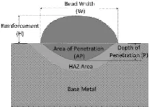
Cladding is a form of surfacing application where a relatively thick layer of a corrosion resistant alloy is deposited on a plain carbon or low alloy steel substrate[1, 2]. Corrosive and high temperature atmospheric conditions demand engineering components to show satisfactory corrosion and/or heat resistant properties. In order to provide long life to carbon steel components at relatively low cost, austenitic stainless steel overlay cladding is done to make them corrosion resistant. Literature reveals that many austenitic stainless steel grades are used for cladding carbon or low-alloy steels [3-8]. Among the fusion welding processes,Gas Metal Arc Welding, Shielded Metal Arc Welding, Gas Tungsten Arc Welding, Flux Cored Arc Welding and Submerged Arc Welding have been used for cladding [3, 5, 7-14]. In the present work, Advanced Submerged Arc Welding process, due to its certain merits over conventional Submerged Arc Welding process, is used for cladding AISI 308L stainless steel on mild steel plate. Amathematical model has been developed to study the effect of ASAW process parameters on weld penetration shape factor (WPSF).Weld penetration shape factor is defined as the ratio of bead width and depth of penetration. It is also called the coefficient of internal shape [7, 15]. Mathematically, WPSF can be represented as = / , where W and P are the Bead Width and Depth of Penetration respectively as shown in Figure 1.
II. ADVANCED SUBMERGED ARC WELDING
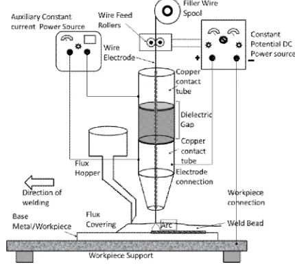
Advanced Submerged Arc Welding (ASAW) is a recently developed welding process in the Welding Research Laboratory of Indian Institute of Technology Delhi (Sunil Pandey, 2004, Patent application number: 2533 / DEL / 2008 Dated: November 07, 2008). Its working principle is based on conventional submerged arc welding process with a difference that the continuously fed wire electrode is electrically preheated with the help of a separate auxiliary power source before it enters into arc region. The contact tube through which the continuous wire electrode is passed is made into two parts which are separated by a dielectric gap. With the help of main power source, welding current is passed through the electrode and the base metal in order to create arc for melting. The auxiliary power source as stated is used to preheat certain length of electrode wire. The schematic diagram of the ASAW setup is shown in Figure 2.
Figure 2: Schematic diagram for Advance Submerged Arc Welding (ASAW) setup
ASAW process, in this way, fetches the energy required to bring the electrode wire in molten state in two steps i.e. through resistance preheating of electrode wire as well as by providing welding current between the electrode and the base metal to create arc. It has been established from the previous research that a striking reduction in welding current due to preheating of electrode is noted during welding which in turn lessens arc force. This leads to lower penetration depth and thus reduced weld dilution and make the process more suitable for surfacing applications [16]
III.EXPERIMENTATION
A. Experimental setup
The experimental runs were performed on Advanced Submerged Arc Welding equipment. A direct current constant potential (DCCP) power source with a rated current capacity of 600 amperes at 60% duty cycle with mechanized welding head was used for the experimentation.
B. Material selection and identification of process parameters limits
A ‘single bead on plate’ technique was adopted to deposit beads of SFA/AWS 5.9 class ER308L stainless steel single bare wire electrode of 3.15 mm diameter on 300 mm x 75 mm x 12 mm mild steel plates. A compatible agglomerated flux of class AWS SFA A-5.23 was used to shield the weld metal from atmosphere. The bead was deposited at the centre of each plate along its length in order to have equal heat dissipation rates on both sides of the bead.
Independent ASAW parameters i.e. wire feed rate F, travel speed S, open circuit voltage Vo and nozzle to plate distance D and preheating current IP were carefully chosen for the present work.
C. Design matrix and experimental procedure
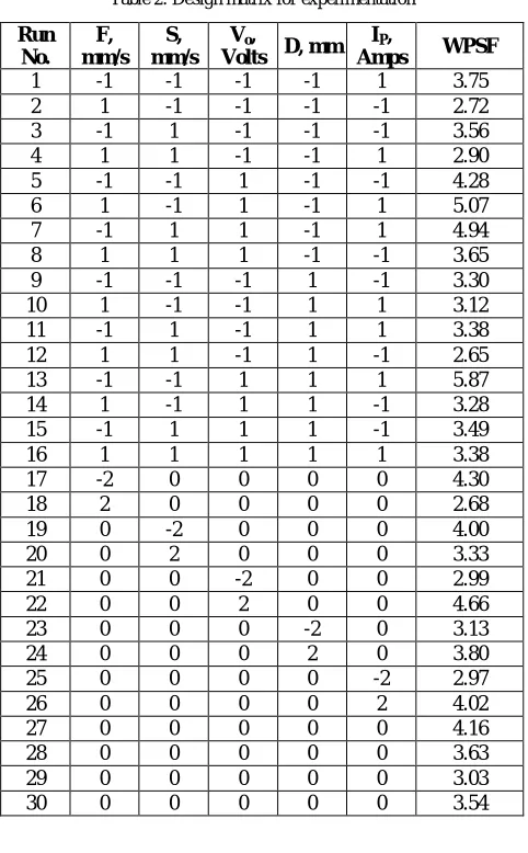
The five levels of each independently controllable ASAW parameters were selected and coded as -2, -1, 0, +1 and +2 as given in Table 1 and then design matrix consisting 30 test conditions based on half fraction rotatable central composite design (CCD) was formed as illustrated in Table 2 using Design Expert 8 statistical software.
Stainless steel beads thus deposited on mild steel base plates according to design matrix were allowed to cool in still air up to room temperature. In order to maintain the uniformity in bead properties and their chemical composition, start and stop portions of 50 mm length were discarded off by cutting both ends of plate. Three bead on plate specimens of about 15 mm width (one at centre and two at both the ends) were then taken out from remaining length of plate. After careful mounting with Bakelite, the specimens were polished sequentially using finer grades of polishing papers. Important bead zones were exposed by etching the specimens with 2% Nital solution. Bead width and penetration were measured by scanning the specimens. . Resulting Weld Penetration Shape Factor (WPSF) corresponding to each test experimental run is also presented in Table 2.
Table 1: Parameters and their values at various levels
Process parameter Units Notation Coded Notation
Parameter levels
-2 -1 0 +1 +2
Wire Feed Rate mm/sec F A 20 24 28 32 36
Travel Speed mm/sec S B 2.5 4 5.5 7 8.5
Open Circuit Voltage Volts Vo C 30 33 36 39 42
Nozzle to plate distance mm D D 18 21 24 27 30
Preheat current Amp. IP E 0 42 84 126 168
IV.DEVELOPMENT OF MODEL
A. Response surface methodology
Response surface methodology (RSM) is useful for modelling and analysis of problems that include number of variables and where objective is to optimize the multiple responses[17, 18]. Response function Y can be expressed in terms of process parameters as
= ( , , , , )
The model includes the main effects and interaction effects of all the factors in the form of first or second order polynomial correlations. Second order polynomial, which was assumed for the current study, is represented by following general equation.
= +∑ +∑ +∑ ∑ + …(1)
Where β0, βiiandβij are constant regression coefficients and xiandxjare the process variable and ϵ is the error term of the model [19].
B. Estimating the adequacy of developed models and significance of coefficients
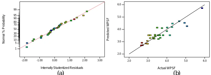
The adequacy of the model was established by using Analysis of Variance (ANOVA) technique[7]. The outcomes of ANOVA for the WPSF are given in Table 3. This table shows details of degrees of freedom (DF), sum of squares (SS), mean square (MS), F- Ratio and Probability of larger F- value or simply P-value. Calculated F-value for the model was found larger than tabulated F-value at 95 % confidence level which indicates the adequacy of the model. The "Pred R-Squared" of 0.7418 is also found in reasonable agreement with the "Adj R-R-Squared" of 0.7908.Figure 3is a normal probability vs. Studentized residuals plot for all the observations of WPSF. It can be determined that the assumption of a normal distribution is judicious since all the plotted points follow a straight line.
Table 2: Design matrix for experimentation
Run No.
F, mm/s
S, mm/s
Vo,
Volts D, mm IP,
Amps WPSF
1 -1 -1 -1 -1 1 3.75
2 1 -1 -1 -1 -1 2.72
3 -1 1 -1 -1 -1 3.56
4 1 1 -1 -1 1 2.90
5 -1 -1 1 -1 -1 4.28
6 1 -1 1 -1 1 5.07
7 -1 1 1 -1 1 4.94
8 1 1 1 -1 -1 3.65
9 -1 -1 -1 1 -1 3.30
10 1 -1 -1 1 1 3.12
11 -1 1 -1 1 1 3.38
12 1 1 -1 1 -1 2.65
13 -1 -1 1 1 1 5.87
14 1 -1 1 1 -1 3.28
15 -1 1 1 1 -1 3.49
16 1 1 1 1 1 3.38
17 -2 0 0 0 0 4.30
18 2 0 0 0 0 2.68
19 0 -2 0 0 0 4.00
20 0 2 0 0 0 3.33
21 0 0 -2 0 0 2.99
22 0 0 2 0 0 4.66
23 0 0 0 -2 0 3.13
24 0 0 0 2 0 3.80
25 0 0 0 0 -2 2.97
26 0 0 0 0 2 4.02
27 0 0 0 0 0 4.16
28 0 0 0 0 0 3.63
29 0 0 0 0 0 3.03
30 0 0 0 0 0 3.54
V. RESULTS
A. Development of Final mathematical models
Following equations have been finalized keeping significant parameter coefficients and omitting insignificant parameter coefficients. Equation 2 represents regressions in terms of coded factors, where B, C and E are the coded symbols for welding speed S, open circuit voltage Voand preheat current IP. Equation 3 shows correlation in terms of actual factors.
1) Final Correlation in Terms of Coded Factors:
= + 0.28 + 0.03 × A + 0.012 × B−0.035 × C−0.021 × E + 0.011 × B × E …(2)
2) Final Correlation in Terms of Actual Factors:
= + 0.5667 + 7.5345 × 10 × −6.3753 × 10 × −11.552 × 10 × −1.458 × 10 × +
Table 3: ANOVA test for the fitted model
Source DF SS MS F-Value P-value
%Contri-bution Significance
Model 5 0.066987 0.013397 22.93 < 0.0001 significant
A-Wire Feed Rate, F, mm/s 1 0.021799 0.021799 37.31 < 0.0001 26.91282 B-Travel Speed, S, mm/s 1 0.003588 0.003588 6.14 0.02060 4.430103 C-Open Circuit Voltage, Vo, Volts 1 0.028826 0.028826 49.33 < 0.0001 35.58803 E-Preheat Current, IP, Amps 1 0.010874 0.010874 18.61 0.00020 13.4243 B×E- Interaction between S and IP 1 0.001899 0.001899 3.25 0.08400 2.344856
Residual 24 0.014000 0.000584 17.28395
Lack of Fit 21 0.009962 0.000474 0.35 0.9383 not significant
Pure Error 3 0.004062 0.001354
Cor Total 29 0.081000 100
R-Squared 0.8269 Adjust
R-Squared 0.7908
Adequate Precision 18.188 Predicted
R-Squared 0.7418
B. Direct effect of ASAW parametrs on WPSF
Regression model equations 2 and 3 show the influence of ASAW parameters on the WPSF and Figure 2(a) represents graphically the individual effect of each parameter on WPSF. In Figure 4(a), A, B, C and E are the coded notations for Wire feed rate F, Travel speed S, Open circuit voltage VO, and Preheating current IP respectively. It is
clearly indicated that WPSF decreases when F and S are increased and it increase when VO and IP are increased. With
the help of ANOVA as shown in table 3, percentage contribution of each ASAW parameter can be evaluated. It can be seen that the parameter which affects the WPSF in the most influential manner is open circuit voltage VO
(%contribution = 35.58) and second comes the wire feed rate F (%contribution = 26.91). Then follow the preheating current IP and Travel speed S (%contribution = 13.42 and 4.43 respectively). In this way travel speed S is influences
WPSF the least. It is to be noted that F is directly controlled by the main welding current.
C. Interaction effect of ASAW parameters on WPSF
Equations 2&3and Figure 4(b) illustrate that only two ASAW parameters i.e. Travel speed S and Preheating current IP have interaction effect on WPSF. As can be seen in Figure 4 (b), at lower level (4.0 mm/s) of travel speed S, rate of
increase WPSF with respect to Preheating current IP is significantly slow as compared to higher level (7.0 mm/s) of the
same. In other word, it can be said that for lower level (42 A) of Preheating current IP, effect of travel speed is
negligible while at higher level (126 A) of IP, travel speed S shows a strong negative effect on WPSF. Surface plots
shown in Figure 5 and Figure 6 illustrate the combined effects of two ASAW parameters simultaneously in different combinations. Plots have been drawn for parameter ranges from -1 to +1 since accuracy of prediction is highest in this range.
(a) (b)
Figure 3: (a) Normal probability vs. Studentized residuals plot, (b) Actual WPSF vs. predicted WPSF curve Internally Studentized Residuals
N
o
rm
a
l
%
P
ro
b
a
b
ili
ty
Normal Plot of Residuals
-2.00 -1.00 0.00 1.00 2.00 3.00 1
5 10 20 30 50 70 80 90 95 99
Actual WPSF
P
re
d
ic
te
d
W
P
S
F
Predicted vs. Actual
2.0 3.0 4.0 5.0 6.0
(a) (b)
Figure 4: (a)Direct effect of individual ASAW variables on WPSF, (b) Interaction effect of welding speed S and preheating current IP on WPSF
(a) (b) (c)
Figure 5: Surface plots showing combined effect of wire feed rate F and (a)Welding speed S (b) open circuit voltage VO (c) preheating current IP on
WPSF
(a) (b) (c)
Figure 6: Surface plots showing combined effect of (a) welding speed S and open circuit voltage VO (b) Welding speed S and preheating current IP (c)
open circuit voltage VO and preheating current IP
VI.CONCLUSION
1. Mathematical model for WPSF in terms of ASAW parameters has been developed.
2. Wire feed rate and open circuit voltage are found to have great influence on WPSF as compared to other ASAW parameters
3. By increasing the wire feed rate and decreasing the open circuit voltage during cladding, decreased values of WPSF can be achieved.
4. An increase in preheating current, which is a special feature of ASAW, WPSF increases.
5. WPSF should be maximized for cladding operations, thus lower levels of wire feed rate and travel speed and higher levels of open circuit voltage and preheating current should be used.
Perturbation
Deviation from Reference Point (Coded Units)
W
P
S
F
-1.0 -0.5 0.0 0.5 1.0
3.0 3.5 4.0 4.5 A A B B C C E E 4.0 5.0 6.0 7.0 24 26 28
30 32 3.0 3.5 4.0 4.5 W P S F F, mm/s S, mm/s 33 34 35 36 37 38 39
24 26 28 30
32 2.0 2.6 3.2 3.8 4.4 5.0 W P S F F, mm/s Vo, Volt 42 63 84 105 126
24 26 28 30
32 2.0 2.6 3.2 3.8 4.4 5.0 W P S F F, mm/s Ip, Amp 33 34 35 36 37 38 39 4.0 5.0 6.0 7.0 2.0 2.6 3.2 3.8 4.4 5.0 W P S F
S, m m/s
Vo, Volt 63 42
84 105 126 4.0 5.0 6.0 7.0 2.0 2.6 3.2 3.8 4.4 5.0 W P S F S, mm/s Ip, Amp 42 63 84 105 126
33 34 35 36
37 38 39 2.0 2.6 3.2 3.8 4.4 5.0 W P S F Vo, Volt Ip, Amp S, mm/s
42 63 84 105 126
REFERENCES
[1] N. Murugan and R. S. Parmar, "Mathematical Models for Bead Geometry Prediction in Austenitic Stainless Steel Surfacing by Mig Welding," Joining Materials, vol. 7(2/3), pp. 71-80, 1995.
[2] Welding , Brazing and Soldering vol. 6. USA: ASM International, 1993.
[3] P. K. Ghosh, P. C. Gupta, and V. K. Goyal, "Stainless Steel Cladding of Structural Steel Plates Using the Pulsed Current Gmaw Process," Welding Journal, vol. 77, pp. 307s- 314s, 1998.
[4] A. S. Shahi and S. Pandey, "Effect of Auxiliary Preheating of the Filler Wire on Quality of Gas Metal Arc Stainless Steel Claddings," Journal of Materials Engineering and Performance, vol. 17, pp. 30-36, 2008.
[5] T. Kannan and J. Yoganandh, "Effect of Process Parameters on Clad Bead Geometry and Its Shape Relationships of Stainless Steel Claddings Deposited by Gmaw," The International Journal of Advanced Manufacturing Technology, vol. 47, pp. 1083-1095, 2010.
[6] A. S. Shahi and S. Pandey, "Modelling of the Effects of Welding Conditions on Dilution of Stainless Steel Claddings Produced by Gas Metal Arc Welding Procedures," Journal of Materials Processing Technology, vol. 196, pp. 339-344, 2008.
[7] P. K. Palani and N. Murugan, "Optimization of Weld Bead Geometry for Stainless Steel Claddings Deposited by Fcaw," Journal of Materials Processing Technology, vol. 190, pp. 291-299, 2007.
[8] P. K. Palani, N. Murugan, and B. Karthikeyan, "Process Parameter Selection for Optimising Weld Bead Geometry in Stainless Steel Cladding Using Taguchi's Approach," Materials Science and Technology, vol. 22, pp. 1193-1200, 2006.
[9] D. J. Kotecki, "Dilution Control in Single Wire Stainless Steel Submerged Arc Cladding," Welding Journal, vol. 65, pp. 35s-45s, 1996. [10] U. D. Mallya and H. S. Srinivas, "Bead Characteristics in Submerged Arc Strip Cladding," Welding Journal, pp. 30-36, 1989.
[11] P. K. Palani and N. Murugan, "Development of Mathematical Models for Prediction of Weld Bead Geometry in Cladding by Flux Cored Arc Welding," International Journal of Advanced Manufacturing Technology, vol. Vol. 30, pp. 669-676, 2006.
[12] J. Tušek and M. Suban, "High-Productivity Multiple-Wire Submerged-Arc Welding and Cladding with Metal-Powder Addition," Journal of Materials Processing Technology, vol. 133, pp. 207-213, 2003.
[13] L. Shan-Ping, K. Oh-Yang, K. Tae-Bum, and K. Kwon-Hu, "Microstructure and Wear Property of Fe-Mn-Cr-Mo-V Alloy Cladding by Submerged Arc Welding," Journal of Materials Processing Technology, vol. 147, pp. 191-196, 2004.
[14] P. K. Palani and N. Murugan, "Sensitivity Analysis for Process Parameters in Cladding of Stainless Steel by Flux Cored Arc Welding," Journal of Manufacturing Processes, vol. 8, pp. 90-100, 2006.
[15] J. Cornu, Advanced Welding Systems vol. 2. London:: IFS Publication, 1988.
[16] D. K. Shukla, "Dilution Control through Advanced Submerged Arc Welding," Ph.D., Mechanical Engineering IIT Delhi, 2009. [17] A. I. Khuri and J. A. Cornell, Response Surfaces: Designs and Analyses: Marcel Dekker Incorporated, 1996.
[18] A. I. Khuri and S. Mukhopadhyay, "Response Surface Methodology," Wiley Interdisciplinary Reviews: Computational Statistics, vol. 2, pp. 128-149, 2010.
[19] D. C. Montgomery, Design and Analysis of Experiments, 5th Ed., 5th ed.: John Wiley & sons Inc, Singapore, 2006.
[20] S. Pandey, "Welding Current and Melting Rate in Submerged Arc Welding: A New Approach," Australasian Welding Journal Supplements, vol. 49, pp. 33 - 42, 2004.
[21] B. Fnides, M. A. Yallese, T. Mabrouki, and J. F. Rigal, "Application of Response Surface Methodology for Determining Cutting Force Model in Turning Hardened Aisi H11 Hot Work Tool Steel," Sadhana, vol. 36, pp. 109-123, 2011.
[22] H. Om, S. Pandey, and D. Rathod, "Mathematical Modeling of Haz in Submerged Arc Welding Process Using Factorial Design Technique”," in Trends and Advances in mechanical Engineering (TAME- 2012), YMCA University of Science & Technology, Faridabad, India, pp. 616-626, 2012.
[23] H. Om and S. Pandey, "Effect of Heat Input on Dilution and Heat Affected Zone in Submerged Arc Welding Process," Sadhana, vol. 38, pp. 1369-1391, 2013.