SUBSTANTIATION OF RELIABILITY OF DEVELOPED SPATIAL
STATIC AND DYNAMIC MODELS OF NATURAL AND PILE
FOUNDATIONS OF NPP STRUCTURES
Akop Sargsian1, Elena Gukova2, and Vitaly Geraschenko3
1
Professor, Head of Research Dept. of Dynamics and Seismic Safety, AEP, Moscow, Russian Federation
2Chief Specialist, Research Dept. of Dynamics and Seismic Safety, AEP, Moscow, Russian Federation
3
Principal Engineer, Research Dept. of Dynamics and Seismic Safety, AEP, Moscow, Russian Federation
ABSTRACT
Spatial static and dynamic models of natural and pile foundation were developed to take into account the effects of the interaction of structures foundation with soil environment under different operating conditions.
The models allow developing and substantiating the optimized design for various purposes for structures foundation, taking into account the geological site conditions in the various operating modes including seismic excitations.
The relevant stiffness and damping on the contact surface of the structure with foundation were introduced into the mechanical mathematical model to consider soil-structure interaction.
Evaluation of internal forces for foundation slab sections is required for validation of the design. The distribution law for the stiffness of soil foundation
was
accepted. The foundation stiffness at an arbitrary nodal point of FEM is in proportional to stress arisen on soil on the contact surface.The comparison of the analysis of the NPP Reactor building and the results of the field studies demonstrated the validity of the reliability of the developed model of the natural foundation. The appropriateness of the use of pile foundations for increased stability and bearing capacity of NPP structures foundations was represented.
The comparative analysis of the results of calculations with the data field for the Moscow Mercury City Tower building carried out for the demonstration of the suitability of 3-D model of pile foundation.
Spatial static and dynamic models of natural and pile foundation were developed to take into account the effects of the interaction of structures foundation with soil environment and approved.
MAJOR PART
Nowadays, both in Russia and abroad, dynamic mechanical model of the natural foundation of the structures [1] is commonly used in the performance of practical calculations.
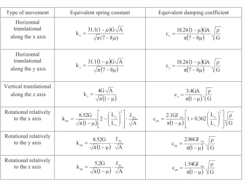
The alternative expressions for static and viscous integral stiffness of the foundation represented as a linear-deformed inertia half-space have been developed and proved in [2, 3].
Table 1
Type of movement Equivalent spring constant Equivalent damping coefficient
Horizontal translational
along the x axis π(7 8 )
A )G -31.1(1 kx m m -=
(
)
(
)
Gρ 8μ 7 π GA μ 1 18.24 cx -= Horizontal translational along the y axis
(
)
(
7 8μ)
π A G μ 1 31.1 ky -=(
)
(
)
Gρ 8μ 7 π GA μ 1 18.24
cy
-=
Vertical translational
along the z axis
(
)
μ 1 π A 4G kz -=
(
)
Gρ μ 1 π 3.4GA cz -= Rotational relatively to the x axis
(
)
AJ L L 2 μ 1 π 8.52G k Ax 2 x y x × ú ú û ù ê ê ë é ÷÷ ø ö çç è æ -=
j
(
)
G ρ L L 0.362 1 μ 1 π 2.1GJ c 2 x y Ax x ú ú û ù ê ê ë é ÷÷ ø ö çç è æ + -= j Rotational relatively to the y axis
(
)
AJ
μ
1
π
8.52G
k y × Ay
-=
j
(
)
G ρ μ 1 π 2.86GJ
cy Ay
-= j
Rotational relatively to the z axis
(
)
AJ μ 1 π 5.2G k Az z × -= j
(
)
Gρ μ 1 π 1.54GJ c Az
z =
-j
where kx, ky, kz, kjx, kjy, kjz – static integral stiffness of the foundation at linear and rotary motions
of the structure relatively to the coordinate axes; cx, cy, cz, cjx, cjy, cjz – viscous integral stiffness of
the foundation at linear and rotary motions of the structure relatively to the coordinate axes; μ– average Poisson ratio for the soil foundation; G – average dynamic shear modulus of a soil base; ρ– average density of a soil base ;A=LxLy – area of the slab bottom;Lx, Ly(Lx³Ly) – length and width of the slab
in plan, along x and y axis respectively; Az Ax Ay
3 x y Ay 3 y x
Ax L L/12, J L L/12, J J J
J = = = + – moments of
inertia of the foundation slab relative to the principal axis of inertia x, y and vertical axis z, passing through the center of gravity of the bottom of the foundation slab.
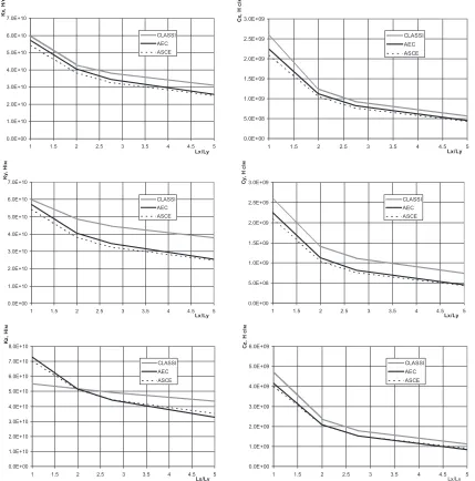
The stiffness graphs of a rigid weightless stamp foundation depending on the ratio of Lx Lycalculated in
accordance to [4] (CLASSI), [1] (ASCE) and [2] (AES) are given in figures 1, 2.
In accordance with [1] (ASCE)
с
jz=
0
, that has not the physical reason, whereas the waves radiation to the foundation should occur during the rotational movement, including a vertical axis z under condition of total adhesion between the stamp and the base.m 51.8
Lx= - fixed length of the stamp on the plan; ρ=2.137
4 2
/m s
kN× density of the soil; μ=0.35 - Poisson ratio of the soil; G=405.5 MPa - dynamic shear modulus of the soil.
Figure 1. Static ( left) and viscous (right) linear stiffness of the foundation of a weightless rigid stamp with the stamp size Lx / Ly variation and Poisson ratio of the soil base μ = 0,35 along the axis x, y, z
0.0E+00 1.0E+10 2.0E+10 3.0E+10 4.0E+10 5.0E+10 6.0E+10 7.0E+10
1 1.5 2 2.5 3 3.5 4 4.5 5
Lx/Ly
K
x
,
Н
/м
CLASSI
АЕС
ASCE
0.0E+00 5.0E+08 1.0E+09 1.5E+09 2.0E+09 2.5E+09 3.0E+09
1 1.5 2 2.5 3 3.5 4 4.5 5
Lx/Ly
C
x
,
Н
с
/м
CLASSI
АЕС
ASCE
0.0E+00 1.0E+10 2.0E+10 3.0E+10 4.0E+10 5.0E+10 6.0E+10 7.0E+10
1 1.5 2 2.5 3 3.5 4 4.5 5
Lx/Ly
K
y
,
Н
/м
CLASSI
АЕС
ASCE
0.0E+00 5.0E+08 1.0E+09 1.5E+09 2.0E+09 2.5E+09 3.0E+09
1 1.5 2 2.5 3 3.5 4 4.5 5
Lx/Ly
C
y
,
Н
с
/м
CLASSI
АЕС
ASCE
0.0E+00 1.0E+10 2.0E+10 3.0E+10 4.0E+10 5.0E+10 6.0E+10 7.0E+10 8.0E+10
1 1.5 2 2.5 3 3.5 4 4.5 5
Lx/Ly
K
z
,
Н
/м
CLASSI
АЕС
ASCE
0.0E+00 1.0E+09 2.0E+09 3.0E+09 4.0E+09 5.0E+09 6.0E+09
1 1.5 2 2.5 3 3.5 4 4.5 5
Lx/Ly
C
z
,
Н
с
/м
CLASSI
АЕС
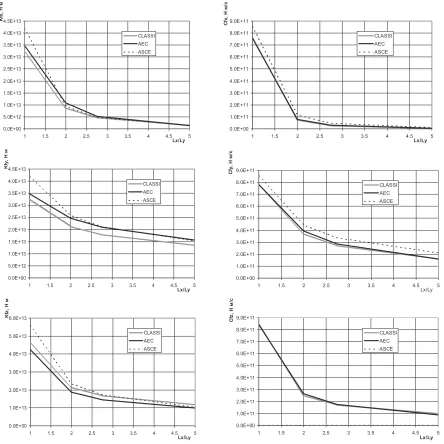
Figure 2. Static ( left) and viscous (right) angular stiffness of the foundation of a weightless rigid stamp with the stamp size Lx / Ly variation and Poisson ratio of the soil base μ = 0,35 about the axis x, y, z
It follows from these results that the use of different models of the foundation developed in accordance with ASCE 4-98 [1] and [2] the difference of the results of calculations is not significantly
.
The validity and acceptability of dynamic model of the foundation developed in [2] are clearly demonstrated by presented results. At the same time the dynamic mechanical model of the foundation proposed in [2] is physically well founded and argumentative in comparison with the model recommended by the ASCE 4-98 [1].
The parameters of static mechanical model of pile foundation are defined by [3, 5].
The following assumptions were accepted forming the resulting reaction of the soil medium on the contact surfaces of the pile and the grillage:
0.0E+00 5.0E+12 1.0E+13 1.5E+13 2.0E+13 2.5E+13 3.0E+13 3.5E+13 4.0E+13 4.5E+13
1 1.5 2 2.5 3 3.5 4 4.5 5
Lx/Ly K fx , Н м CLASSI АЕС ASCE 0.0E+00 1.0E+11 2.0E+11 3.0E+11 4.0E+11 5.0E+11 6.0E+11 7.0E+11 8.0E+11 9.0E+11
1 1.5 2 2.5 3 3.5 4 4.5 5
Lx/Ly C fx , Н м /с CLASSI АЕС ASCE 0.0E+00 5.0E+12 1.0E+13 1.5E+13 2.0E+13 2.5E+13 3.0E+13 3.5E+13 4.0E+13 4.5E+13
1 1.5 2 2.5 3 3.5 4 4.5 5
Lx/Ly K fy , Н м CLASSI АЕС ASCE 0.0E+00 1.0E+11 2.0E+11 3.0E+11 4.0E+11 5.0E+11 6.0E+11 7.0E+11 8.0E+11 9.0E+11
1 1.5 2 2.5 3 3.5 4 4.5 5
Lx/Ly C fy , Н м /с CLASSI АЕС ASCE 0.0E+00 1.0E+13 2.0E+13 3.0E+13 4.0E+13 5.0E+13 6.0E+13
1 1.5 2 2.5 3 3.5 4 4.5 5
Lx/Ly K fz , Н м CLASSI АЕС ASCE 0.0E+00 1.0E+11 2.0E+11 3.0E+11 4.0E+11 5.0E+11 6.0E+11 7.0E+11 8.0E+11 9.0E+11
1 1.5 2 2.5 3 3.5 4 4.5 5
- With horizontal movement soils undergo simple shear on the sole grillage;
- With vertical movement on the sole grillage soils are compressed;
- The condition of total adhesion is broken when tensile stresses occur on the lateral surface of the pile, based on the condition that the soil tensile does not work;
- With vertical movement of the pile across the lateral surface soils undergo simple shear and compression on the sole pile;
- For the horizontal displacement of the pile on the side surfaces occurs simple shear. There is compression in the front wall, separation of soil from the wall surface of the pile in the rear wall and simple shear on the sole.
Design parameters of integral stiffness of soil medium on the contact surface of the sole grillage are determined by the expressions given in Table 2 [3, 5].
Table 2
Type of movement Equivalent spring constant
Horizontal translational
along the x axis
(
)
(
1)
s,1 1 x
8μ
7
π
A G
μ
1 31.1 k
-=
Horizontal translational
along the y axis
(
(
)
)
1 s,1 1 y
8μ
7
π
A G
μ
1 31.1 k
-=
Horizontal translational along the z axis
(
1)
s,1 z
μ
1
π
A 4G k
-=
where μ1– average Poisson ratio of the surface layer of the soil medium at sole grillage level;
Gs,1 - average dynamic shear modulus of the surface layer of the soil medium at sole grillage level;
A– area of the sole grillage in the plan.
Figure 3. Distribution of contact stresses on the lateral surface(a) and sole(b) of the pile with circular cross section when moving along the direction of the coordinate axes x, y, z accordingly.
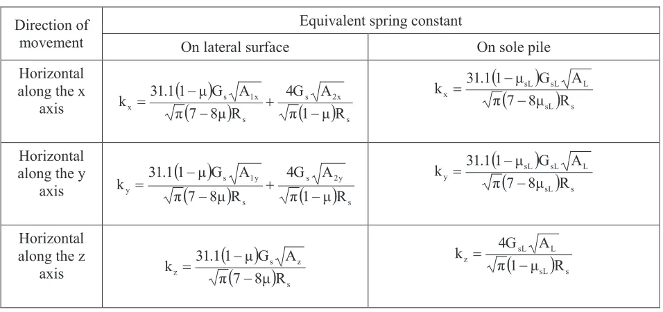
Design parameters of integral static stiffness of soil medium on the contact lateral surface and on the sole pile are determined by the expressions given in Table 3.
Table 3
Direction of movement
Equivalent spring constant
On lateral surface On sole pile
Horizontal along the x
axis
(
)
(
)
(
)
s2x s s 1x s x R μ 1 π A 4G R 8μ 7 π A G μ 1 31.1 k -+ -=
(
)
(
sL)
sL sL sL x R 8μ 7 π A G μ 1 31.1 k -= Horizontal along the y
axis
(
)
(
)
(
)
s2y s s 1y s y R μ 1 π A 4G R 8μ 7 π A G μ 1 31.1 k -+ -=
(
)
(
sL)
sL sL sL y R 8μ 7 π A G μ 1 31.1 k -= Horizontal along the z
axis
(
)
(
)
sz s z R 8μ 7 π A G μ 1 31.1 k
-=
(
sL)
sL sL z R μ 1 π A 4G k -=
where A - area of lateral of the contact surface with the soil medium undergo shear when moving along 1x the x axis ; A - area of lateral of the contact surface with the soil medium undergo compression when 2x moving along the x axis; A - area of lateral of the contact surface with the soil medium undergo shear 1y
when moving along the y axis; A - area of lateral of the contact surface with the soil medium undergo 2y
compression when moving along the y axis; A - area of lateral of the contact surface with the soil z
For a pile with circular cross section 1x πdhc
6 1
A = ; 2x πdhc
6 1
A = ; 1y πdhc
6 1
A = ; 2y πdhc
6 1
A = ;
c z πdh
A = ; 2
L πd
4 1
A = ;
d- cross section diameter; hc- height of piles; Rs
-
correction factor taking into account the effects of theinteraction of the pile in the composition of the pile bush [3, 4, 6].
Design model was developed in accordance with the specified design building solutions.
The transition from a constructive scheme for the finite element model is carried out by replacing the real structures for the finite elements.
The spring –dashpot, beam, shell and special contact elements were used for the system soil –structure model development.
General view of the computational model of the building is shown in Figure 4
Figure 4 - General view of a computational model of the building
A comparison of vertical settlement of structure grillage established by the results of field observations and from the analysis [5, 7] is given in Table 4.
Table 4
GM number Uz by of analysis, mm Uz from field data, mm Uz by SP analysis, mm
79 -10.36 -12.6 -
37 -5.11 -4.98 -
72 -3.75 -5.47 -19.4
55 -4.16 -2.9 -
51 -4.40 -3.85 -
44 -5.75 -6.62 -
82 -7.77 -6.5 -
46 -5.66 -9.2 -
76 -9.06 -10 -
39 -8.41 -8.6 -
97 -7.02 -9.6 -17.6
74 -4.30 -3.6 -
47 -4.64 -5.4 -19.7
45 -4.34 -3.9 -
38 -6.64 -6.9 -
100 -13.39 -15.1 -26.2
85 -13.89 -14.3 26.9
108 -11.08 -10.8 -25
87 -12.91 -14.2 -24.8
103 -12.88 -14.8 -15.6
102 -12.60 -13.7 -15.6
89 -12.74 -14.4 -24.8
95 -15.10 - -
94 -15.22 - -
67 -3.13 -3.5 -
1 -2.43 -0.3 -
12 -3.13 -1 -
56 -3.77 -1.6 -
70 -6.38 -3.7 -
3 -2.79 -2.9 -
65 -4.59 -8.5 -
6 -3.04 -3.9 -
51 -5.32 -3.8 -
9 -3.02 -3.1 -
58 -4.07 -4.8 -
99 -10.82 -10.3 -23.9
96 -10.90 -13.2 -20.8
93 -14.21 - -19.1
92 -13.38 - -
91 -11.67 - -
83 -11.70 -11.5 -24.2
84 -12.37 -13.1 -25.4
49 -4.56 -4.3 -
36 -3.80 -2 -
25 -3.48 -1.4 -
43 -8.05 -8.1 -
where GM number- number of geodetic mark, Uz –vertical displacement.
The following types of finite elements were used in 3-D model of system soil –structure of reactor building:
- 4-node shell elements for plane construction elements (walls, floors and diafragms); - 3-d beams (columns and crossbars);
- rigid beams (to provide load transmission eccentrically);
- mass elements to simulate loads of equipment that can be considered as concentrated loads.
Development of a model of system soil - structure was implemented using ANSYS
The spatial finite element model of the reactor building is shown in Figure 5.
Figure 5 - General view of the finite element model of the reactor building.
Design reduced static characteristics of soils in the core of the natural base:
modulus of elasticity E= 38 MPa; Poisson ratio µ= 0.4; shear modulus G= 13.57 MPa.
Integral static stiffness of natural foundation on the slab bottom: kx =ky=2.58×10⁶ kN/m;
kN/m. 10
3.64
k 6
z = ×
To perform comparative calculations let us to determine the design parameters of the base in the implementation of pile foundation.
Diameter of circular cross section piles d=0.6 m, height hc =18.0.
In accordance with requirements [6] the distance between the axes of driven piles hanging 1.8m
3d m 2.0
Δx,y = ³ =
The total number of piles in the pile bush is 1089.
Design parameters of the integral static stiffness of soil medium on the lateral contact surface and on the sole of the piles were defined by the expressions presented in Table 3.
Design characteristics of soil environment:
X Y
Z
Gs =9.16 MPa
-reduced
static shear modulus of soil base ; µ=0.33-
Poisson ratio of soil base, adjustmentheight of location pile field ; GsL =5.4MPa, μsL =0.39 -shear modulus and Poisson ratio at piles soles level; Rs=4.2- correction factor that takes into account effects of interaction of piles as part of the pile
bush [3, 5, 6 ] .
Total integral static stiffness of foundation of reactor building considering interaction effects of grillage
and pile bush with soil medium k k 5.358 10 kN/m; k 3.764 107kN/m.
z 7
y
x = = × = ×
The presented results demonstrate that the stiffness of the foundation of the structure in the implementation of the described embodiment of the pile foundation exceeds an order of magnitude stiffness of the natural foundation.
Let us define the settlement of the reactor building of NPP with and without pile foundation .
Settlement of natural foundation Δnat =0.736m. According to the data of field observations and the results of numerical studies the settlement of foundation of the reactor building reaches 0.7m
Therefore, the estimated value Δnat =0.736m agrees with the field observations and numerical studies of the natural foundations of the NPP structures [6]. It should be noted that the amount of settlement
m 0.736
Δnat = significantly exceeds the permissible structure settlement under normal operating
conditions Δno=0.1m.
The settlement in the implementation of pile foundation is set to
( )
m 0.10
Δ
m 0.071 k
Q
Δ no
pf z
pf = = á = .
Therefore, the settlement of the foundation of the structure in the implementation of the pile foundation significantly adjusted and its value as opposed to natural foundation complies with current regulations [6].
REFERENCES
ASCE STANDARD (1998) Seismic Analysis of Safety Related Nuclear Structures. Aproved September,
1998, ASCE, Reston, VA, USA.
Sargsian, А. Е., Gukova E. G. and Grishin A.S. (2009) “Generation of Dynamic Mechanical Model of Inertial Soil Foundation in Consideration of NPP Structures Basement Finite Stiffness”, Theory of
Structures. CNIISK Herald, CNIISK, (1), 81-95
Sargsian, А. Е. (2013) Dynamic and Seismic Stability of NPP Structures. Sarov, FSUE «RFNC - VNIIEF», 550 .
CLASSI. Definition of Dynamic Stifness of Rigid Stamp of Arbitrary Shape in Plan. University California, San Diego, CA, USA.
Sargsian, А. Е., Geraschenko V.S., Borchev К.S. (2014). “Substantiation of Reliability of Developed Model of Pile Foundation of field data for Mercury City Tower building”. Collected papers of ТС
207 ISSMGE, St.Petersburg, Russia, 82-87
MR 1.5.2.05.999.0026 – 2011 (2011) Design Standards for NPP Structures Foundations. Moscow, Russia