ABSTRACT
CHALKE, YATIN DATTARAM. Automatic Generation and Execution of Specification-Based Test Cases in a Network Specification-Based Environment. (Under the direction of Dr. Mladen Vouk)
Automatic testing of software has always been of interest. The concept has been receiving more and more attention in the software development climate of today (e.g., agile software processes) where managers and testers are being asked to turn around their products under shorter schedules and with smaller resources. Automation is being looked at as a pathway to meet the product testing and delivery deadlines. There are many research methods and tools, as well as a number of commercial tools that automate test design, generation and execution. Some are specification-based, some are structure based, and some are combinations of both. However the current state of automation of software testing has problems. These include design and maintainability of automation (e.g., current methods may not track product changes in a cost-effective way, and test-case suites do not always evolve easily and consistently), generation of excessive number of test-cases, end-user friendliness of the tool interfaces, measurability of the test-suite effectiveness, and so on.
network-based systems, and c) assess usability of pair-wise testing strategy and automation of testing in an industrial environment.
DEDICATION
To my
Parents
To my
brother
Ojas
BIOGRAPHY
ACKNOWLEDGEMENT
I would like to thank Dr. Mladen Vouk, my advisor, for his guidance, and motivation and for providing the opportunity to work with him. Dr. Vouk has been instrumental in bringing me to the field of Networking and Testing and I am glad I got the chance to work with him.
I would like to thank Dr. Edward Gehringer for being on my thesis committee and providing invaluable advice and support in so many ways over past two years. I would like to thank Dr. Laurie Wiliams for accepting to be a committee member and providing useful comments on this thesis from time to time.
I would like to thank Mr. Christopher Lott from Telcordia for granting us the trial version of AETG for research use.
I would like to thank my friends for being there when I needed them.
Finally, I would like to thank my parents and family for their support and love. Thanks Mom for all the encouragement, you are the reason I am here. Thanks Dad for faith in me. Thanks Ojas for your support. Words alone cannot express the thanks I owe to my family, for their moral and emotional support.
Table of Contents
LIST OF FIGURES………..……….VIII
LIST of TABLES...X
CHAPTER 1………..1
INTRODUCTION………..1
1.1 Background………...…1
1.2 Nature of Testing...………..…2
1.3 Specification-Based Testing...4
1.4 Automatic Test Case Generation………....…...…5
1.5 Translation, Execution and Analysis………...6
1.6 Organization of Thesis...7
CHAPTER 2 ………...……8
AUTOMATED TEST CASE DESIGN………...…..8
2.1 Test Generation Approaches...8
2.2 Code-Based Test Generation………...…9
2.3 Interface-Based Test Generation……….……...9
2.4 Specification-Based Test Generation……….….10
2.5 Test Automation Framework Approach (TAF)...13
2.5 Pairwise Strategy………..…...16
2.6 Illustration of Pairwise Strategy …………....………….………...…..17
2.8 Summary...18
CHAPTER 3………...…….19
IN-PARAMETER ORDER ALGORITHM………...……...19
3.1 The In-Parameter Order (IPO) Strategy...19
3.2 An Algorithm for Horizontal Growth...21
3.3 Algorithm IPO_H (Τ, Pi)……….………...…………22
3.4 An Algorithm for Vertical Growth……….………...…….22
3.5 Algorithm IPO_V (Τ, π)…………..………....…..23
3.6 PairTest Test Generation Tool...24
3.7 Test Generation Tools…………...26
3.8 Automatic Efficient Test Case Generator...27
3.9 PairTest Evaluation………...………...……29
3.10 Test Case Parameters and Specifications………...…....29
3.11 Relations………...…....31
3.12 Constraints………...…..32
3.13 Test Set………...….….34
3.14 Comparison of PairTest………...…..………...34
3.14.1 Performance Issues………...……34
3.14.2 Efficiency Considerations………...…37
3.14.3 Case Study-2: Network Processor Example (Practical Use)...41
3.14.3.1 Case Study-2: PairTest Testing...43
3.14.3.2 Case Study-2 :AETG Testing...49
3.14.3.3 Case Study-2: Manual Tests...53
3.14.4 Discussion...57
3.15 Drive for Automation...59
CHAPTER 4………...……….60
AUTOMATION USING ‘EXPECT’………...…………...…..60
4.1 Objectives of Test Automation...60
4.2 Metrics of Test Automation...61
4.3 Automated Test Life- Cycle Methodology (ALTM)……....………...63
4.3.1 Practical Implementation...65
4.4 Common Problems in Test Automation ...69
4.5 Current Problems in Industrial Automation...70
4.5.1 Commitment of Automation...70
4.5.2 Choice of Automation...71
4.5.3 Approach for Late Start on Test Automation...71
4.6 Intelligent Test Automation...72
4.7 Benefits of Test Automation...76
CHAPTER 5………....78
VALUE OF AUTOMATION...………..…....78
5.1 Introduction...78
5.2 Experiment...79
5.3 Metrics...84
5.3.1 Fault Coverage...84
5.3.2 Efficiency...88
5.3.3 Resources...91
5.3.4 Test Development Resources...93
5.3.5 Test Execution Resources...97
5.3.6 Evolvability...101
5.3.8 Test Execution Evolvability...105
CHAPTER 6………...110
CONCLUSIONS………..…....110
6.1 Summary...110
6.2 Conclusion...112
6.3 Future Work...113
REFERENCES………...….114
APPENDIX A………...…...122
APPENDIX B...154
List of Figures
Figure 1 Test Specification Elements...15
Figure 2 Edit Parameter window for PairTest (GUI Version)……….…………..………..31
Figure 3 Edit Relations window for PairTest (GUI Version)………..…....32
Figure 4 Edit Constraints window in PairTest (GUI Version)……...……….33
Figure 5 Parameter Values ………..………..38
Figure 6 Relations……….……….………...……39
Figure 7 Test Set Using PairTest...………40
Figure 8 Test Set from PairTest (Network Processor Example)…..………..…..49
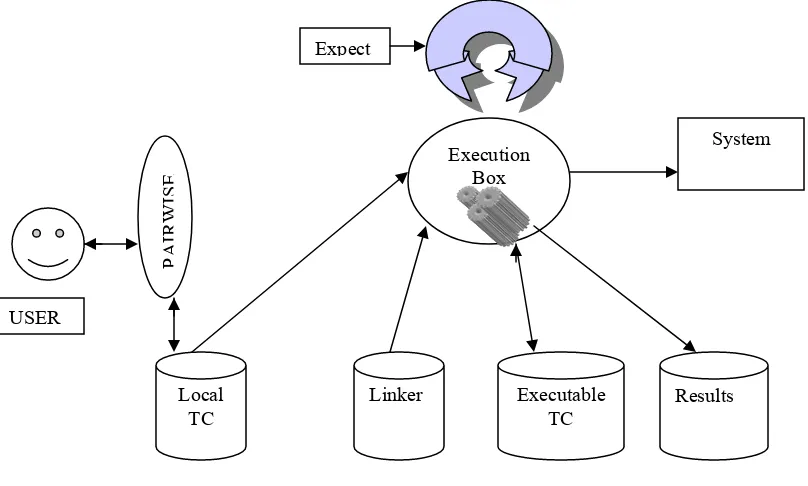
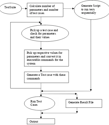
Figure 9 Test Generation and Automation Process………..………..………....66
Figure 10 Test Automation Process………..…..68
Figure 11 Test-Bed...80
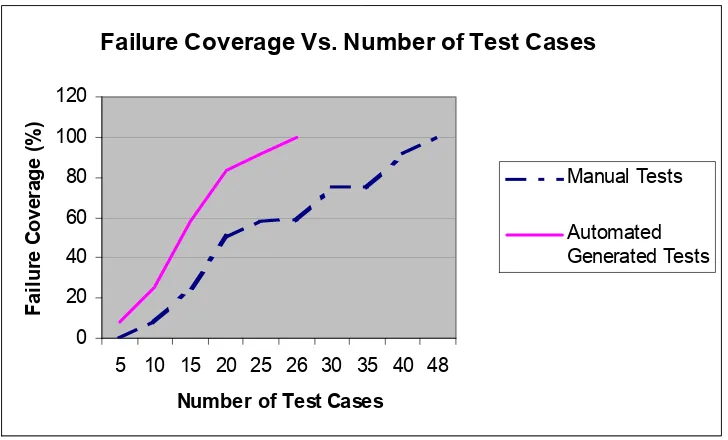
Figure 12 Failure Coverage Vs. Number of Test Cases (PairTest)...86
Figure 13 Fault coverage Vs. Number of Test Cases (PairTest)...87
Figure 14 Number of Test Cases Vs. Failure Coverage- INDUSTRIAL...87
Figure 15 Per Test Case Efficiency Vs. Number of Tests...90
Figure 16 Average Testing Efficiency Vs. Failure Coverage...91
Figure 17 Resource Distribution over Testing period- INDUSTRIAL...93
Figure 18 Resource Rate Vs. Time (Test Generation- PairTest) - LABORATORY...94
Figure 19 Resource Rate Vs. Time (Test Generation) - INDUSTRIAL...96
Figure 20 Resource Rate Vs. Time (Test Execution) data - LABORATORY...99
Figure 21 Resource Rate Vs. Time (Test Execution) - INDUSTRIAL...100
Figure 22 Evolvability Vs. Time (Test Generation – PairTest) - LABORATORY...103
Figure 23 Evolvability Vs. Time (Test Generation) -INDUSTRIAL...104
Figure 24 Evolvability Vs. Time (Automation) – LABORATORY...106
Figure 26 Edit Parameters from AETG………..………154
Figure 27 Edit Relations from AETG……….155
List of Tables
Table 1 Fault/Failure Coverage Vs. Number of Test Cases Data...85
Table 2 Resources Vs. Time (Test Generation) data...94
Table 3 Resources Vs. Time (Test Execution) data...98
Table 4 Evolvability Vs. Time (PairTest – Test Generation) data...102
Table 5 Evolvability Vs. Time (Automation) data...105
Table 6 Test Suite Analysis for Per Test Case Efficiency...147
Table 7 Executable values of test cases - PairTest...148
Table 8 Executable values of test cases – Manual Test ...149
Table 9. Manual Test Generation Incremental configuration...150
Table 10. Manual Test Execution Incremental configuration...150
Table 11. Failure Coverage data –Industrial...151
Table 12. Test Generation- Industrial Resources...151
Table 13. Test Execution- Industrial Resources...152
Table 14. Evolvability –Industrial (Test Generation)...152
Chapter 1
Introduction
1.1 Background
Testing is a process of establishing confidence that a program or system does what it is supposed to do [Few99]. Software has to go through many stages to reach an acceptable level of this confidence. The developed software has to be thoroughly checked to see that it serves its purpose. This checking is effected by verification, validation and testing [Adr82; IEEE97; Pres92]. Verification, validation and testing are ongoing processes which start with the software requirements and continue even after the development is completed. Software testing is one of the most visible aspects of this process. It is also a very challenging task.
Showing that software is 100% correct can be done in only two ways – through
program proving and through exhaustive testing. Neither is a realistic option in general practice. The former is usually too expensive; the latter is usually defeated by the test-case (state) explosion problem. A partial answer, but a promising one, to this problem is a combination of
b) a method that allows automatic translation of above test cases from its abstract form into its executable form
c) a method that allows a resource efficient execution of the test cases
d) a method that allows a resource-efficient evaluation of the results of test-case execution, and
e) a resource-efficient way of updating/maintaining the test-suite in the face of changes in the software it is intended to test.
Automation of some of the elements above is what this thesis investigates.
1.2 Nature of testing
Testing cannot guarantee the absence of faults1 in complex computer-based systems [Het88]. “If you think your task is to find problems, you will look harder for them than if you think your task is to verify that the program has none” [Myers1979]. Hence, the purpose of the software testing is detection of failures, defects and faults rather than demonstration of their absence [Bei83]. Testing can be used only to show the presence of faults [DDH72]. The basic reason is the discrete nature of digital computer software and by implication testing. For example, if two test points in the input space of a piece of software (the space of all external inputs and stimuli a software program can receive directly or indirectly, including external interrupts) have been tested successfully, one can only conjecture about the behavior of the software for other inputs situated between or close to these test points. Hence, exhaustive testing (testing of all program input states) is desirable, however infeasible.
Exhaustive testing requires that a program’s responses be evaluated for all possible inputs [Bla98]. For example, one may have to consider [Bei95] the following.
• Testing the program for all valid inputs.
• Testing the program for all invalid inputs.
• Testing the program for all edited (changed/ mis-typed) inputs.
• Testing all variations on input timing.
• Testing the program for all combinations (Almost infinite)
Obviously, for anything but trivial specifications, the test cases will grow in numbers very fast. It is often unrealistic to expect that all possible test cases can be developed to start with, let alone run and analyzed. Yet, if any of the cases from the “exhaustive” suite are not run, it means the program was only tested in part.
Consequently, only what is considered to be a representative subset of inputs is usually manifested as real-life test suites. This means that, in practice, testing only shows that a system behaves correctly with respect to the requirements pertaining to the actual test cases run, the transitivity of that quality to intermediate states is an
assumption. The issue is that of selection of “representative” test cases that assure that this assumption, and the resultant conclusions about the transitivity of the ascertained quality of the product, hold true all the time or at least most of the time.
start as soon as software development starts, they have to be flexible and adaptive, and they have to be pervasive. More recently, the issue has been highlighted by agile development processes [Aoy97; Aoy98; Gla01; New02; Boe02; Sch01]. In fact, selecting an appropriately timely and dynamic verification, validation and testing process and strategy is the key to combating the burden of “exhaustive” testing. .
1.3 Specification-Based Testing
In this thesis we focus on the test case generation and automation methods that derive from software specifications rather than structural characteristics. The aim is to develop test-suites that are both fault-effective (fault-sensitive) and resource-effective (e.g., small number of test cases).
In practice, almost 30% of testing effort is spent in writing test cases [Bla98]. Yet, these test cases may or may not be effective in actually detecting faults. Hence, the test-design and/or test-case generation algorithm(s) plays major role in generating efficient test cases. Unless fault-sensitivity, ability of test cases to detect faults, is the primary driver for test case development strategy, other factors, such as software life-cycle phase priorities or time constraints, may dictate test-suite composition. For example ad-hoc testing [Bei83] is the need to generate test cases which run only once and provide some immediate situation-specific assurances or feelings of adequacy. Alternately regression tests [Rot02; Mal02] serve as “benchmark” against which the product is tested repeatedly to assure that changes do not break functionalities that worked before the changes were made. This requires test cases which are not only very fault-efficient and resource-efficient, but also adapt to changes in the software in a cost-effective way.
specifications provide the best basis for test case generation [Eka91; Boc88]. Unfortunately, a common drawback is that a large gap between a formal test-case generation strategy and the ability to automatically generate cost-effective executable test-cases. As mentioned earlier the issues are: test-design strategy (algorithms), translation of these cases into executable suites, actual execution of the test-suite, the development of an oracle for being able to tell when the results of test execution are correct, and adaptability and maintainability of test-suites.
There are a number of papers discussing the issue in automatic test case generation and automatic test execution [Dus99; Few99; Gri02; Hu01]. The former aspect, issue of automatic test generation, deals with item a) and e) of section 1.1 – a method to take formalized specifications and easily develop effective and efficient test suites. The later, automatic test execution, deals with items b), c) and d) – ways to automate generation, execution and analysis of the test suites and their results. This thesis is focused specifically on automation of the translation between abstract test-cases generated using an automated formal strategy, in this case PairTest [Coh94; Coh96; Tai01; Tai02], and on automation of test-execution of such test-cases.
1.4 Automatic Test-Case Generation
A major obstacle to automatic generation of test cases using specifications is the required support for going from the test-case design to the actual testing (design-to-test ability). Underlying development models often do not support automatic (design-to-test vector generation for specification based testing [Bla98; Hie97]. There are many techniques available to convert such models into ones that do incorporate design-to-test for automatic design-to-test vector generation [Hie97; CHJ88]. However most of the approaches make the maintenance of generated test cases expensive with changes.
resource-efficient way for automatic test case generation using specifications, but also it has a reasonable maintenance overhead. Management of the generated test cases is simplified by TAF through the use of verification models which transform specifications into a pre/post condition pairs called test specification elements. In the present case, TAF was applied to the In-Parameter Order algorithm [Tai01], a member of the pair-wise testing family of solutions [Coh94; Coh97; Ding99; Wil96]. This model identifies the requirements in terms of logical entities representing the input parameters and the environment of the system under test. The verification part of model adds inter-parameter relations and constraints. The model is quite efficient in the number of test-cases it generates, and it appears to have very good fault-detection properties [Ding99; BBNC01; Tai01; DKLL98]. The model based on In-Parameter Order algorithm has been available as an open source abstract test-case generation tool called PairTest [Tai01; Tai02].
This work enhances the tool based on In-Parameter Order algorithm in two ways: (1) its handling of parameter options, and (2) the translation of abstract test-suites into executable test-suites.
1.5 Translation, Execution and Analysis
Efficient translation of formally developed test cases into executable test cases is very desirable. However, the actual execution of test cases and the analysis of the results for correctness is often more time consuming than test case development. The “oracle” issue is not within the scope of the present work, but translation and execution are.
generated test-suite to account for incremental changes in the system specifications (requirements, design, environment, etc.) incrementally adaptable to changes in the system. “The management and performance of test activities, to include the development of executable tests and execution of test scripts so as to verify test requirements, with adaptability to changes is needed ” [Few99].
Development of application-specific test-drivers, software that effects translation of abstract test cases into executable test cases, can be very time consuming and error prone. This can lead to high maintenance costs. This is an issue that agile methodologies address explicitly, since early automated testing is often an integral part of such strategies [Poo01; Gla01; Boe02; New02, Sch01; Aoy98]. The resource efficient and adaptable test automation can be addressed using solutions such as the Automated Test Life-cycle methodology (ALTM) [Dus99]. This methodology can be used to provide a structured approach for automated execution of test cases leading to development of an adaptable test script. The ALTM concept was adopted in this work to develop a resource efficient and adaptable test script for translation, automated result analysis and execution of test cases generated by PairTest.
1.7 Organization of Thesis
Chapter 2
Automated Test Case Design
2.1 Test Generation Approaches
The process of testing involves many stages. The stages of identifying the requirements or test areas and design of test cases are considered intellectual activities [Few99]. Whereas, stages of execution of test cases and comparison of test outcomes are much more repetitive. The intellectual activities affect the quality of the test cases. In contrast repetitive activities are time consuming and boring.
Thus, activities of test execution and comparison are repeated many times, while the activities of identifying test conditions and designing test cases are performed less times. Due to limited time available for testing, testers have to select test cases which will be executed. But as there can be infinite conditions in an input domain, the choice of such cases becomes very important thus indicating need for effective test generation process. This emphasizes need of high fault detection capability for effective test generation.
2.2 Code-based test generation
Code-based test generation approach develops test inputs by examining the structure of the software code itself. A path through the code is composed of segments determined by branches at each decision point. The conditions required to produce such paths can be provided automatically to generate paths through the code.
The code-based test generation approach generates test inputs. But expected outcomes are required for each test for verification and analysis of the test results. Any code based test case design cannot tell whether the outcomes produced by the software are the correct values. So this approach is incomplete, since it cannot generate expected outcomes. A Test-Oracle is the source of the correct expected outcomes but a code based test generation scheme has no test-oracle [Het88].
Another type of code-based test design approach can generate tests to satisfy weak mutation testing criteria. Mutation testing is where the code or input is changed in some small way to see if the system can correctly deal with this mutated version. But still, such code-based test generation approach to satisfy weak mutation testing does not provide the appreciable level of fault detection coverage [Het88]. The main reason for this is attributed to newly generated execution paths through the changed code which reduce the fault detection ability.
2.3 Interface-based test generation
An interface-based test generation approach can generate tests based on some well-defined interface, such as GUI or web application. If a screen contains various menus, buttons and check boxes, this approach can generate test cases which can check each such menu. For example, test cases generated by this approach can verify if a check box is checked or if a field is selected.
page and then do it for each of the pages linked to recursively. The interface-based approach can be useful for identifying some functionality-related defects. An expected outcome can be partially generated, but only in a very general sense and kind of in the binary form as it can just identify a correct working result and wrong result. This approach cannot tell if all the outcomes are logically right.
This approach can therefore generate tests by generating test inputs and thus identifying some functionality errors. It can be defined to be partial oracle [Het88]. It is very helpful in performing a ‘roll-call’ testing [Het88] which means that it can test everything which should be there is there. Testing using test cases generated this way can be too tedious to do manually as it take lot of patience and time which defeated our goal of development of an efficient test case generation scheme.
2.4 Specification-based test generation
Specification-based test generation refers to creating test inputs from the software specifications. It allows tests to be created early in the system development and to be ready for execution, which simplifies incorporating changes in the test cases with changes in system. Additionally specifications can be used as a basis of output checking which can lead to reduction in one of the major costs of testing, the cost for analysis of the test results. The specification-based testing technique provides another advantage by keeping the essential part of the test data independent from the particular implementation of specifications. It can generate test inputs and also expected outputs, provided that the specification is in a form that can be analyzed by the tool. The specification may contain structured natural language constraints, such as business rules, or it may contain technical data as states or transitions. So, these tests do have an automatically-generated test oracle [Het88].
which tests are concentrated at what the software should do rather than concentrating at what software does [HJL96]. This helps in avoiding test generation for satisfying developed software criterion by sidelining the actual requirements. For such test generation expected outcomes can be generated if they are stored in the specification. Most of the defects in software are due to lack of consistency in implementation of requirements. Boehm and Basili state that finding and fixing a problem late in the development process can be more expensive than finding and fixing it during the requirement or design phase [BB2001]. Thus specification-based testing approach can help generate a cost-effective technique with high fault detection ability.
The limitations of the above mentioned automated test case generation approaches can be summarized as.
• Code-based methods do not generate expected outcomes.
• Interface-based methods can only generate partial expected outcomes.
• Code-based and interface-based methods find very less specification defects.
Considering these aspects of the test generation approaches, it can be seen that the approach using requirements of the software as a criterion to generate test cases, can help identify most defects thus increasing fault detection capability [Ding99; Hu01; BF98]. Thus specification-based test generation approach can be used to generate tests with high fault detection ability which can check software requirements effectively.
State-based specifications describe software in terms of states and transitions. Typical state-based specifications define conditions on transitions, which are values that specific variables must have for the transition to be enabled. The triggering events
[Ding99], which are changes in variable values that cause the transition, are evaluated in specification-based testing. A triggering event is a change in one or more variable that can cause a transition to enter a new state [Ding99].
In comparison of full-predicate testing, transition-pair specification-based technique fares better due to its ability of fault detection for valid sequences [Ding99]. This ability gives it the edge in fault detection ability which indicates that a strategy based on transition-pair specification strategy can help in development of an efficient approach for automated test generation. Such a strategy using this principle is discussed in section 2.6.
2.5 Test Automation Framework (TAF) Approach
As from the above discussion it can be inferred that transition-pair specification-based test generation technique can provide high fault detection capability resolving the need for efficient test generation method. However, such a technique needs to be modeled for automated test case generation. Use of formal specifications to provide a basis for test case generation has been in use [Eka91]. Goodenough and Gerhart may have been the first to claim that the testing based only on a program implementation is fundamentally flawed [GG75]. Gourlay developed a mathematical framework for specification-based testing [Gou83]. A model-based specifications approach constructs an abstract model of the system states and characterizes how a state is changed by abstract or concrete operations [CHJ88; CGDDTK96]. The state changes or events that affect the model using existing mathematical constructs like sets and functions define operations in the system. State transitions define relationships between sequences of states based on conditions of system state. Event specifications define certain conditions related to change in the system state. A test specification element can be defined as an input-to-output relation. An associated constraint is defined by conjunction of Boolean value relations which define constraints on the inputs associated with the input to output relation.
requirements by automatic changes in tests generated. Model transformations are typically required to transform model-based specifications into a form which supports test generation. Hierons described writing rules for Z specifications [Hie97] to support test case generation, but did not address specifications composed of combinations of specification techniques; particularly specifications composed using event specification techniques. Model transformation to support test generation interoperability is an important aspect for development of cost-effective and efficient automated test generation scheme. Blackburn [Bla98] described an approach for transforming the model-based specification into a form which can support test vector generation but failed to identify composition of function and state specifications. Thus, the drawback of ineffective and expensive translation of specification-based test generation models was the issue in realizing the goal of developing an efficient automated test generation method.
To overcome the drawback of the ineffective translation of specification-based test generation models for automatic test generation leading to inefficient use of resources the Test Automation Framework (TAF) approach was evaluated. The core capabilities underlying the TAF approach were developed in the late 1980s and were shown to be effective through use in support of FAA certifications for flight critical avionics systems [BB96]. Statezni described how this approach supports requirements- based test coverage mandated by FAA with significant life cycle cost savings [Sta00]. Safford presented results stating the approach reduced cost, effort and cycle time by eliminating requirements defects and automating test generation process [Saf00]. The National Institute of Standards and Technology (NIST) assessed TAF approach as the basis for a methodology and supporting toolkit to automate major aspects of security functional testing [BBNC01].
The benefits of this approach can be summarized as
• Use of models for verification reduces the time spent on verification test planning by up to 50 percent [Saf00]
• Test generation from a verification model helps to eliminate most of the manual test creation effort.
• Use of verification models for test generation helps in early defect identification.
• Ability to plan a known level of requirement coverage for analysis purposes during test execution helps in adaptation of test execution for changes.
Thus, TAF can be used to improve fault detection which can lead to reduction in resource consumption. The key change from othe automated test generation approaches is the introduction of verification models for development of automated test vectors. These models support automated means of identifying model defects and generating tests that are highly effective in verifying a system consistent with the model. The TAF translator transforms and expands Software Cost Reduction (SCR) [Hei95] specifications into a form supporting automatic test generation [BBNC01]. For model analysis and test generation, the model is transformed into a set of precondition/ post condition pairs referred as Test Specification Elements as described in Figure 1. Test vector generation is then carried out to produce a test vector for every test specification element [BBF97].
Figure 1. Test Specification Elements
Set of Specification Elements
Constraint 1 Output = f 1 (inputs) Or
Constraint 2 Output = f 2 (inputs) Or
Constraint 3 Output = f 3 (inputs) Or
. . .
Thus TAF approach can be used to generate automated test vectors in a cost effective way from test specifications. The use of this approach allowed us to provide a resource-efficient technique for automatic test case generation which can handle changes in requirements effectively.
2.6 Pairwise Strategy
Our goal is to provide a resource-efficient and effective approach for automated test generation. To be consistent with this goal, we have seen the benefits of specification based test generation to provide high fault detection capability and use of TAF approach to provide a cost-effective way for automated test generation. However another major issue affecting the automated test generation is generation of large number of test cases as specifications change. The motivation behind automated test generation, to provide a fast and effective way of test generation is almost nullified due to these large numbers of test cases. In this section we evaluate a transition-pair specification-based strategy called Pairwise in our effort to tackle issue of generation large number of test cases.
The notion of pairwise coverage of parameter values in software testing was first put forth by Mandl [Man85] for testing Ada compiler. Mandl used testing the types of operands as part of equations as an example in using pairwise coverage of parameters. Pairwise strategy considers pair of parameters for test generation. A possible trade off of pair wise between test coverage and the number of tests can be to determine a set of test configurations that test each pair wise combination of parameter values. This implies that for any two parameters of the system each combination of the possible values of the two parameters occurs in at least one test configuration. This is the basic principle of pairwise strategy.
any coverage has thorough coverage [Wil02]. In addition, it guarantees that all interfaces have been exercised as all combinations are covered at least once. These properties of pairwise strategy resolved the issue of generation of large number of test cases. However, pair wise parameter coverage cannot guarantee detection of problems involving a specific combination of three or more parameter values. The idea of using pairwise (or n-way) interactions among parameters as a coverage strategy for system testing has been useful in practice in a variety of situations [Wil96]. This strategy is illustrated with an example in the following section.
2.7 Illustration of Pairwise Strategy
Consider the following system of parameters to illustrate the concept of pairwise testing.
• Parameter A has values A1 and A2
• Parameter B has values B1 and B2
• Parameter C has values C1, C2 and C3
For parameters A and B, {(A1, B1), (A1, B2), (A2, B1), (A2, B2)} is the only pairwise
test set.
However, when we consider the three parameters A, B and C then there exist A (2) * B (2) * C (3) = 12 test cases with full dependence of parameter values on each other. Pairwise strategy states that each combination of valid values of a pair of parameters appears at least once in a test case. This provides partial dependence in the values of the parameters thus eliminating the redundancy.
When we consider parameters A, B and C a large number of pairwise tests exist depending on the heuristics applied. Example of such pairwise test suite is given.
• { (A1, B1, C1), (A1, B2,C2), (A2, B1,C3), (A2, B2, C1), (A2, B1,C2), (A1, B2,C3) }
• The strategy in [Coh97] starts with an empty test set and adds one test at a time. To generate a new test, the strategy produces a number of tests according to a greedy algorithm and then selects one that covers the most uncovered pairs.
• Another approach to generate pairwise test set is to use orthogonal arrays [Man85]. The original method of orthogonal arrays required that all parameters have the same number of values and that each pair of values be covered the same number of times [Man85].
2.8 Summary
We evaluated the code-based, interfaced-based and specification-based test generation approaches for choice of a test generation approach helpful in automatic test case generation. Specification-based test generation technique showed relatively better fault detection ability than code-based and interface-based test generation techniques. We also evaluated drawbacks of specification-based test generation for automated test generation. We discussed use of TAF approach to eliminate those drawbacks to provide a cost-effective automated test generation technique using specification-based test generation. We illustrated use of pairwise strategy to tackle the issue of generation of large number of test cases providing a good level of test coverage.
Chapter 3
In-Parameter Order Algorithm
Pairwise testing is a specification-based testing criterion that requires for each pair of input parameters of a system, every combination of valid values of these two parameters be covered by at least one test case. An algorithm based on pairwise strategy using greedy heuristics called In-Parameter Order algorithm was developed by Dr. K. C. Tai at North Carolina State University.
3.1 The In-Parameter (IPO) order strategy [Tai01]
The In-Parameter Order (IPO) method was developed by Dr. Tai [Tai01]. The method is based on the well-known greedy heuristics for set covers but is adapted to the interaction test coverage problem. The greedy heuristics for set covers is as follows:
Instead IPO applies this heuristics to choosing parameter values individually, instead of selecting an entire test configuration at once. It starts with a small problem of selecting the first two parameters, and creating no * n1 test configurations to cover all
the combinations among those parameters. In this case, parameters are not ordered by the number of values which indicate that there is no assumption that no >= n1. Then
the solution is expanded in two dimensions. The first dimension is horizontal. Then another parameter is added and new values for the added parameter must be selected. These parameters are selected to cover the most number of pairs of parameter values as illustrated in the section 3.2. After this phase, there may still be uncovered pair wise combinations between the added parameter and the previous parameters. By using the greedy heuristic again, new test configurations are added to cover the missing combinations.
Thus for a system with two or more parameters, the IPO strategy generates a pairwise test set for the first two parameters, extends the test set to generate a pairwise test set for the first three parameters, and continue to do so for each additional parameter. The extension of the existing pairwise test set for an additional parameter contains following steps.
• Horizontal growth, which extends each existing test by adding one value of the new parameter [Tai01].
• Vertical growth, which adds new tests, if necessary, to the test set, produced by horizontal growth [Tai01].
3.2 An algorithm for Horizontal Growth [Tai01]
The horiozontal growth algorithm in IPO can be described as follows:
Assume that T is a pairwise test set for parameters p1,p2,……. And pi-1. The horizontal growth of T for parameter pi is to extend each test in T by adding a value of pi
[Tai01]. A high-level algorithm called IPO_H for growth of T for parameter pi is shown in section 3.3.
An explanation of IPO_H involving the system described above can be given as follows.
{ (A1, B1), (A1, B2), (A2, B1), (A2, B2) } is the only pairwise test set for A and B as
described in section 2.6. Since C has three values C1, C2 and C3, these values can be
added to the existing pairwise test set to extend it as (A1, B1), (A1, B2) and (A2, B1) by
adding C1, C2 and C3 respectively.
The new extended tests are (A1, B1, C1), (A1, B2, C2) and (A2, B1, C3). Thus the
resulting set of missing pairs is { (A2, C1), (B2, C1), (A2, C2), (B1, C2), (A1, C3), (B2,
C3) }.
Now we need to choose one of C1, C2 or C3 for the remaining pair (A2, B2). If we add
C1 to it then the extended set will cover the two missing pairs namely (A2, C1) and
(B2, C1).
If we add C2 to the (A2, B2) the extended set (A2, B2, C2) will cover one missing pair
namely (A2, C2). If we add C3 to the (A2, B2) the extended set (A2, B2, C3) will cover
only one missing pair namely (B2, C3). So we choose (A2, B2, C1) as our fourth choice
of test as it covers more missing pairs thus reducing number of tests.
Still the following pairs are not covered: (A2, C2), (A1, C3), (B1, C2) and (B2, C3)
3.3 Algorithm IPO_H( Τ, pI ) [Tai01]
// Τ is a test set. But Τ is also a list with elements in arbitrary order. {Assume that the domain of p1 contains values v1, v2, ……., and vq;
Let Π = {pairs between values of pI and values of p1,p2, …….and , pI-1 }; If (|Τ| <= q )
{
for 1<=j<=|Τ|, extend the jth test in Τ by adding value vj and remove from Π pairs covered by the extended test;
} else {
for 1<= j <=q, extend the jth test in Τ by adding value vj and remove from Π pairs covered by the extended test;
for q < j <=|Τ|, extend the jth test in Τ by adding one value of pI such that the resulting test covers the most number of pairs in Π, and remove from Π pairs covered by the extended test;
}
}
3.4 An algorithm for Vertical Growth [Tai01]
To illustrate the vertical growth algorithm let us consider that the horizontal growth for parameter pi has produced a test set T for p1, p2 …… and pi. Let us consider that
resulting Τ is a pairwise test set for p1, p2,………, pi. In the vertical growth algorithm “–“ represents the unspecified or any value of the parameter.
After the complete run of the IPO_V (Vertical Growth) algorithm the Τ (Test Set) may contain “–“ values. If pi is the last parameter, each “–“ value for pk, such that
1<= k <=I, is replaced by any value of pk. Otherwise, these “–“ values are replaced by
parameter values in the horizontal growth algorithm for pi+1 as follows.: Assume the
value у of pi+1 is chosen for the horizontal growth of a test that contains “–“ as the value for pk , 1<k<i. If there are uncovered pairs involving y and some values of pk , then “–“ for pk is replaced by any value of pk.[Tai01]
Again considering the example system described above we can show that the horizontal growth of parameter C generates the following four tests. (A1,B1,C1),(A1,
B2, C2), (A2, B1,C3) and (A2,B2,C1) and that these four tests do not cover following
four pairs : (A2,C2),(A1,C3),(B1,C2) and (B2,C3). Now we use IPO_V algorithm to
construct a new test to cover these four pairs. To cover (A2,C2) we generate test (A2,–
,C2). To cover (A1, C3) we generate (A1,–,C3). To cover (B1, C2) we change (A2,–,C2)
to (A2,B1,C2) without adding a new test. To cover (B2,C3) we change (A1,–,C3) to
(A1,B2,C3) similarly without adding a new test. Thus only two new tests are generated
to cover the four pairs not covered by horizontal growth. So generated pairwise test will have six tests.
3.5 Algorithm IPO_V(Τ, Π ) [Tai01]
{ Let Τ’ be an empty set ;
for each pair in Π
{ assume that the pair contains value w of pk , 1 <= k < i, and value u of pI;
if ( Τ’ contains a test with “−” as the value of pk and u as the value of pI) modify this test by replacing “−” with w;
add a new test to Τ’ that has w as the value of pk, u as the value of pI, add “−” as the value of every other parameter;
};
Τ = Τ U Τ’ ; };
As illustrated above the IPO strategy performs well according to the sizes of generated test sets by generating fewer test cases to cover all combinations. Also, IPO strategy can be easily extended to reuse the existing test sets when systems are modified due to changes in input parameters and/or their values as illustrated in earlier sections [Tai01]. This provides a very useful cost-effective way of automatic test generation, accounting for requirement changes in test system. Thus IPO strategy provides a way to handle issue of large number of test cases with high adaptability for changing requirements in a cost-effective way. This is in accordance with our goal to provide a resource efficient way of automatically generating manageable number of effective test cases. So we enhanced PairTest, an automated test generation tool based on IPO strategy, to provide a stable open-source automated test generation tool. The PairTest is described in section 3.6.
3.6 PairTest Test Generation Tool
A test case generation tool can prove a boon to the testers considering tough deadlines and deliverables in today’s industry. It can help testers to save some time by automatic generation of test cases to do decent amount of testing. Studies show that total testing time is just 30% of what it should be [BF98].
have low tolerance to incorporate requirement changes in test generation. However, these tools are relatively more thorough, accurate and faster than a human tester using the same algorithm.
In an effort to provide solution to these problems with test generation tools, PairTest, an automated test generation tool based on IPO strategy, was developed in Java [Sun] by Dr. Tai [Tai01]. PairTest version 1.0 was released in 1998. However, PairTest had crashing bugs. Also conversion of a large test system in terms of PairTest parameters was tedious and time consuming. To achive our goal, we modified the PairTest tool to facilitate error free working of the tool. One major issue was the failure of the tool for incorporation of the ‘–‘ values or ‘don’t care’ values during test generation. We modified the tool such that the tool can be used to generate the test set and extend it for generation of new test set to accommodate the change in parameters. We also added a text-based version of PairTest in addition to the GUI version. PairTest was enhanced to add the feature of adding Parameters, Relations as well as Constraints from files which made adding large data very easy. Many feature such as parameter addition, test generation etc. were modified in the tool to correct the crashing bugs in the tool and make it more reliable. Flexibility of the tool was enhanced by addition of the text based version of the tool which helps to run in the tool in different operating environments.
The enhanced version 1.1 of PairTest is available as an open-source automated test generation tool.
The benefits of the PairTest tool can be summarized as follows.
• Automates tedious aspects of test case design.
• It can generate a complete set of test cases with respect to their source.
3.7 Test Generation tools
From the industrial experience it is observed that test generation can become a bottleneck for product in the competitive nature of the industry by increasing the time required for the product to reach markets. In the past two decades, various test development automation tools have been introduced and gradually accepted by designers and test engineers to automate dozens of tasks that are essential for developing adequate tests. The test development automation tools can generally be classified into four categories as below [BB96].
• Design-for-testability (DFT) tools
• Test pattern generation tools
• Pattern grading tools
• Test program development and debugging tools.
DFT tools are used early in the design process and are often used by the design engineers instead of test engineers. Tools in this category include testability analysis tools, design rule checkers and test-structure insertion tools. Testability analysis tools report areas of a design that could cause testability problems (e.g. areas that have poor controllability or poor observability). These tools provide useful guidance in the redesign for improved testing ability [Zin97]. Different test structures (boundary scan, internal scan, memory Built-In-Self-Test (BIST) and logic BIST) impose slightly different design rules. Violations of the test case design rules have to be fixed before test structure can be inserted to avoid changes in the testing ability of tools for test generation. Test pattern generation tools attempt to automatically generate high-quality tests for specified fault models. Automatic test pattern generator (ATPG) is one of the most used pattern generation tool. There are a number of automatic test case generation tools available but these can suffer from combinatorial explosions in the number of possibilities to test [Wat96].
technique to generate tables of test vectors, which a test driver can then execute immediately. Code coverage is then used to indicate missing functionality from AETG’s model. AETG specifically promises to generate fewer test cases than other tools. This results in less time to test the product and verify results [Coh95]. The term “test vectors” is used as opposed to test cases as in most practical situations, AETG does not create actual test cases, but a table of input values needed to execute the desired test cases.
Test case generation in AETG is based on the greedy heuristics of pairwise coverage of parameter values in software testing process which was introduced by Mandl [Man85] for testing Ada compiler. This is the same technique used to develop IPO algorithm used to implement PairTest tool. Test generation ability of PairTest was effectively assessed in industrial as well as controlled laboratory environment. The comparison is discussed in section 3.9.
3.8 Automatic Efficient Test Case Generator (AETG)
The first report on AETG [Coh94] introduces the idea of a combinatorial approach to test generation based on statistical experimental design techniques. The use of the system is then described such that the user has to enter the set of fields (parameter values) and relations (dependencies among parameters). AETG can also generate n-way interactions and not just pair wise interactions. As for how AETG determines its designs, Telcordia has declared those algorithms as proprietary. However, there are clues that greedy heuristics may be involved as shown in section 3.8.1 [Coh96; Wil96]
vectors, a brief introduction to the basic constructs is necessary. The two main components of AETG are Relations and Fields [Coh96]. In terms of testing, a field is usually considered to be an input, and relations are simply how these fields or inputs interact with each other. In essence, a tester must determine the different possible values for each field in a relation. After these requirements have been captured, AETG will then proceed to find the minimal set of test vectors to cover a subset of all interactions. AETG is also able to generate test vectors covering 3-way or n-way interactions.
The test configurations in AETG are generated using greedy heuristic, where the objective is to find the maximum number of uncovered pairs at any stage [Coh97]. This helps to handle the issue of combinatorial explosion of test cases. PairTest also handles this issue in similar way. Also there is a random element to the heuristic and therefore the exact results are not predictable in advance. Code coverage is then used to indicate missing functionality from AETG’s model.
3.8.1 AETG’s algorithm to add new configuration [Coh94]
Algorithms for AETG are described as proprietory by Telcordia. The following algorithm is depicted in the first report [Coh94] of AETG. It gives a slight idea how test generation is implemented in AETG.
• Choose a parameter and a value for that parameter, such that the parameter value appears in the greatest number of uncovered pairs
• Choose a random order for remaining parameters.
• For each parameter, for each possible value for the new parameter, choose the value that covers the most pairs with the previously assigned parameters.
parameters. This helps in reduction of the generated number of test cases thus helping to contain combinatorial explosion problem in generation of test cases which is based on pairwise strategy of test generation. Actual algorithm of AETG is proprietory to Telcordia.
3.9 PairTest Evaluation
Our goal was to develop a resource-efficient approach with high fault detection capability for automated test generation. The implementation of such a method is seen in terms of PairTest, a tool for automated test generation. To verify success of this goal it is necessary to illustrate test generation ability of PairTest tool in industrial environment by analysis with different case studies.
The AETG Web Service offers facilities for creating and editing AETG system input, for using the AETG algorithms to create test sets, described in Chapter 3, and for viewing test sets created by the AETG System. We are thankful to Mr. Christopher Lott from Telcordia for providing us with a free trial account of AETG for research purposes. AETG trial versions can be obtained from http://aetgweb.argreenhouse.com. The AETG Web service generates efficient test sets by creating a small number of test cases such that all pairwise, triple, or n-way interactions of the field values are covered. AETG can generate n-way test sets but as PairTest tool based on IPO algorithm generates test sets by using 2-way interactions so we will be focusing on on pairwise test generations by PairTest.
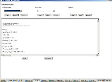
3.10 Test Case Parameters and Specifications
displayed in Figure 2. The screenshot of edit parameter page for AETG is displayed in Figure 26 in Appendix B.
AETG has one more parameter field for specifying the values for continuous parameter that is absent in PairTest. A compound is composed of fields and (optionally) other compounds. A compound value is named tuple [Coh96]. A tuple is an array that has at least one value for each field or compound in the compound.
PairTest test generation staretgy can be described as
• PairTest has a GUI as well as a command line-based option for editing as well as creating a new test plan which runs on any machine with JDK 1.2[Sun] or higher version.
• PairTest allows the parameter values to be entered while entering the parameters. So one does not have to wait till relations are created containing respective parameters to enter respective parameter values.
Figure 2. Edit Parameter Window for PairTest (GUI Version)
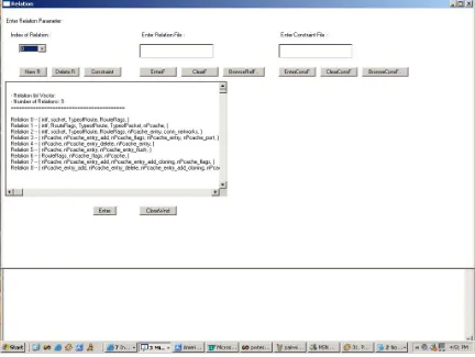
3.11 Relations
At least 2 steps are necessary to create a new relation.
• Selecting the fields and compounds required for creating the relation.
Figure 3. Edit Relations window for PairTest (GUI version)
In addition to select valid values of fields for the relations, AETG also lets set the invalid values of the fields in the relation [Coh96]. While creating relations, values for fields are entered. A number of constraints can be added for a given relation. Relation editing for PairTest is shown in Figure 3. The screenshot for edit relation page for AETG is displayed in Figure 27 in Appendix B.
In PairTest relations are selected by choosing the parameter names to add in a new relation. There is no restriction on duplicating parameters in multiple relations.
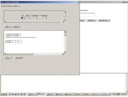
3.12 Constraints
The overview of syntax for valid constraints can be given as follows.
Ex: iffieldiopvalue1thenfieldjopvalue2
In AETG the constraints can be entered as logical statements. The logical operators as =, !=, < , <= , > and >= can be used for defining a constraint statement. The screenshot for edit constraint page for AETG is displayed in Figure 28 in Appendix B.
In PairTest the constraints do not involve logical operators. Moreover they are defined as a static constraint by choosing one of the values of the parameters in relation with the other parameters. In order to cover the parameter value range PairTest allows a parameter value to be denoted as (*) which signifies parameter can take any defined value.
3.13 Test Set
The AETG system generates test cases based on the fields, compounds, and relations in a test specification [Coh94]. When any test set is generated, the test case generation process for current specifications is displayed in PairTest.
In PairTest the test set can be generated by two options.
1. Replace: When the test set is generated with this option an existing file is modified with the new values of parameters, relations and constraints.
2. Extend: This option generates test set by combining the existing specifications with the new added specifications and generates the new test set.
This allows PairTest to generate new test sets as well as modify existing test sets without much effort.
3.14 Comparison of PairTest 3.14.1 Performance issues
Result of PairTest with N 4-value parameters
N(# of parameters) 10 20 30 40 50 60 70 80 90
S (# of tests) 31 34 41 42 48 54 59 61 66
T (Time in seconds) 0.25 0.37 0.42 0.64 0.77 0.98 1.37 1.81 2.23
Results of PairTest with 10 parameters each having d values
D (# of values) 5 10 15 20 25 30
S (# of tests) 47 169 361 618 956 1355
T( time in seconds) 0.19 0.41 0.72 1.89 3.75 5.16
Sizes of tests generated by AETG and PairTest [Tai02]
System S1 S2 S3 S4 S5 S6
AETG 10 17 33 26 13 191
PairTest 8 18 36 25 15 216
S1 : 4, 3-value parameters S2 : 13, 3-value parameters
S3 : 61, parameters(15 4-value , 17 3-value , 29 2-value parameters) S4 : 75, parameters (1 4-value , 39 3-value, 35 2-value parameters) S5 : 100, 2-value parameters
S6 : 20, 10-value parameters
These values are results of the tests run 25 times to take average value of the GUI-based as well as command line version of PairTest. Also the results vary along with modifications made to relation and constraints vectors.
Comparison of other performance related issues are given as follows.
• Ease of use
new test set. PairTest allows change in specifications after a test set generation to generate a new test set with the edited specifications.
Also the GUI as well as command line versions of PairTest provide user-friendly interfaces, which allow users to generate test sets and edit them as per their needs easily.
• While entering constraints, PairTest allows the parameter value to be specified as (*) which signifies all the values of the parameter. So there is no need to enter the constraint for each value of parameter which saves the tedious work of entering constraint for each value of parameter.
• PairTest also provides an option of adding parameters, relations and constraints from the files automatically. These files must be in specific format specified in the help section of the PairTest. This saves the tedious work of entering the parameters/relations/ constraints (saves much work when there are more than 100 parameters) and increases speed of PairTest by some extent.
• Parameter values need to be entered when the parameter is selected in a relation. So when a parameter appears in duplicate relations its values need to be entered again. In case of PairTest it allows the parameter values to be entered at the instant parameter is entered. So relations can choose parameter values without need for re-entering them.
3.14.2 Efficiency considerations
Evaluating and comparing the efficiency of the PairTest algorithm is a difficult task. It has specific ways of specifying the parameters, their values as well as relations and constraints though its underlying strategy is pairwise.
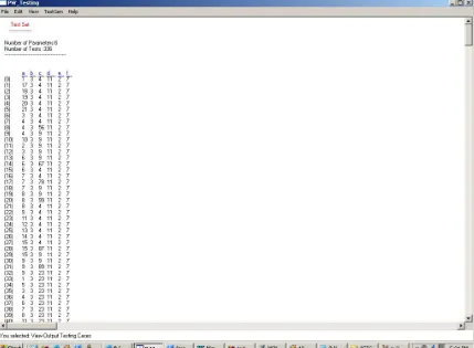
Following examples illustrates and compare the efficiency of PairTest.
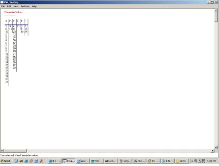
Case Study – 1
Figure 7. Test Set using PairTest
The PairTest file as well as AETG test set is displayed in Appendix B. Screenshot of PairTest test cases can be seen in Figure 7.
By comparing the two test sets we come to a conclusion that there is some difference in the number of test cases generated by AETG as well as PairTest. The basic difference lies in that fact that AETG algorithm can be used to add parameters n-way to generate test cases where as PairTest uses only pairwise addition of test parameters. In the above case study numbers of test cases generated by PairTest are slightly higher than AETG. This is due to the use of (*) Any values allowed by PairTest in defining constraints.
3.14.3 Case Study -2: Network Processor Example (Practical Use)
Using the author’s experience as a co-op in in the area of network processors we tried to test a system of network processors PairTest.
The system under test involved a network processor having 24 ports, each of which could be connected to a different network. Network processor was running vxWorks [vx] operating system. The software developed kept track of all the networks connected to the network processor. It also listened on a routing socket to keep track of any routing packet received by the kernel and process it. Network processor then dynamically added the necessary routes in its forwarding cache to keep it updated. Routes added by the kernel by cloning some other network route also needed to be maintained by the forwarding cache of the system.
Following types illustrate sample of route changes in the system.
• Routes can be network or host routes.
• Routes can be cloning/cloned/static routes.
• Routes can be added for the system in which network processor is on 1. Local Networks
2. Remote Networks 3. CPU Hosted
• Route changes can involve addition, deletion or information transfer.
The system is converted to give inputs to AETG as well as PairTest. The conversion of the system to parameters is listed below.
Interface : intf 0 = Down
1 = UP
Type of Routing Packet : TypeofPacket 0 = RTM_GET
2 = RTM_DELETE
3 = Default
Socket Connection : socket
0 = Unsuccessful 1 = Successful
Route Type : TypeofRoute
0 = Network
1 = Host
Route Flags : RouteFlags 0 = Static 1 = host 2 = Network 3 = Cloning 4 = Cloned
nP Forwarding Cache : nPcache
0 = Invalid
1 = Valid
nP Search Engine : nPcache_se
0 = Absent
1 = Present
nP Cache Delete Entry : nPcache_entry_delete
0 = Unsuccessful
1 = Successful
nPcache Add Entry : nPcache_entry_add 0 = Remote Network 1 = Remote Host 2 = Local Network 3 = Local Host
4 = CPU Hosted Network 5 = CPU Host
nPcache Cloned Route : nPcache_entry_add_cloning 0 = Not cloned
1 = Cloned Route
2 = nP_Valid
nPcache Entry Type : nPcache_entry
0 = Remote Network Entry 1 = Local Network Entry 2 = CPU Hosted Entry
nPcache Ports : nPcache_port 0 = Port not added 1 = Port added
Connected Networks : conn_networks
0 = No Network connected 1 = Networks Connected
nPcache Events : nPcache_event 0 = Add event 1 = Remove Event 2 = Update Event 3 = Flush Event 4 = Delete Event
5 = Destination Unknown Event 6 = Source Mismatch Event
nPcache Flush : nPcache_flush 0 = Unsuccessful 1 = Successful
3.14.3.1 Case Study -2: PairTest Testing
To generate the test set using PairTest these parameters and their respective values were entered. The dependencies among these parameters are converted in terms of relations and constraints, which are listed below.
PairTest File
PARAMETERS
Number of Parameters :16 param:intf-0|1|
param:socket-0|1| param:TypeofRoute-0|1| param:RouteFlags-0|1|2|3|4| param:nPcache-0|1|
param:nPcache_se-0|1|
param:nPcache_entry_delete-0|1| param:nPcache_entry_add-0|1|2|3|4|5| param:nPcache_entry_add_cloning-0|1| param:nPcache_flags-0|1|2|
param:nPcache_entry-0|1|2| param:nPcache_port-0|1| param:conn_networks-0|1|
param:nPcache_event-0|1|2|3|4|5|6| param:nPcache_entry_flush-0|1| RELATIONS
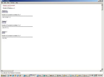
Number of Relations :9
relation:0-(intf,socket,TypeofRoute,RouteFlags,) CONSTRAINTS
Number of Constraints :2 constraint:0-<1,1,0,*,> constraint:1-<1,1,1,*,>
relation:1-(intf,RouteFlags,TypeofRoute,TypeofPacket,nPcache,) CONSTRAINTS
Number of Constraints :3 constraint:0-<1,1,1,*,1,> constraint:1-<1,0,0,*,1,> constraint:2-<1,4,1,*,1,>
relation:2-(intf,socket,TypeofRoute,RouteFlags,nPcache_entry,conn_networks,) CONSTRAINTS
constraint:0-<0,*,*,*,*,*,>
relation:3-(nPcache,nPcache_entry_add,nPcache_flags,nPcache_entry,nPcache_port, )
CONSTRAINTS
Number of Constraints :6 constraint:0-<1,0,0,0,*,> constraint:1-<1,1,0,0,*,> constraint:2-<1,2,1,1,*,> constraint:3-<1,3,1,1,*,> constraint:4-<1,4,2,2,*,> constraint:5-<1,5,2,2,*,>
relation:4-(nPcache,nPcache_entry_delete,nPcache_entry,) CONSTRAINTS
Number of Constraints :0
relation:5-(nPcache,nPcache_entry,nPcache_entry_flush,) CONSTRAINTS
Number of Constraints :1 constraint:0-<1,*,1,>
relation:6-(RouteFlags,nPcache_flags,nPcache,) CONSTRAINTS
Number of Constraints :4 constraint:0-<0,0,1,> constraint:1-<1,0,1,> constraint:2-<2,1,1,> constraint:3-<4,2,1,>
relation:7-(nPcache,nPcache_entry_add,nPcache_entry_add_cloning,nPcache_flags,) CONSTRAINTS
constraint:1-<1,3,1,1,>
relation:8-(nPcache_entry,nPcache_event,) CONSTRAINTS
Number of Constraints :3 constraint:0-<0,5,> constraint:1-<1,6,> constraint:2-<2,6,>
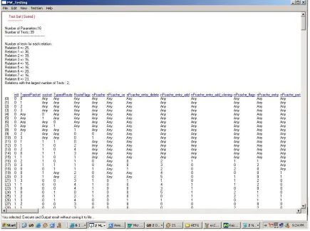
After entering these relations and constraints the test set was generated which is listed below:
Test Set by using PairTest :
[TESTSET]
NUM OF VARS:16 NUM OF TESTS:39 0:intf(0:0,1:1,)
1:TypeofPacket(0:0,1:1,2:2,3:3,) 2:socket(0:0,1:1,)
3:TypeofRoute(0:0,1:1,)
4:RouteFlags(0:0,1:1,2:2,3:3,4:4,) 5:nPcache(0:0,1:1,)
6:nPcache_se(0:0,1:1,)
7:nPcache_entry_delete(0:0,1:1,)
8:nPcache_entry_add(0:0,1:1,2:2,3:3,4:4,5:5,) 9:nPcache_entry_add_cloning(0:0,1:1,) 10:nPcache_flags(0:0,1:1,2:2,)
13:conn_networks(0:0,1:1,)
14:nPcache_event(0:0,1:1,2:2,3:3,4:4,5:5,6:6,) 15:nPcache_entry_flush(0:0,1:1,)
1 1 0 0 3 0 0 0 0 0 2 2 0 0 1 1 1 0 0 0 0 0 0 0 0 0 0 0 0 0 0 0 1 0 0 0 0 0 0 0 0 0 0 0 0 0 6 0 1 0 0 0 4 0 0 0 1 0 2 0 0 0 3 0 1 0 0 0 3 0 0 0 2 0 0 1 0 0 3 0 1 0 0 0 2 0 0 0 5 0 0 2 0 0 4 0 1 0 0 0 0 0 0 0 2 0 0 2 1 0 5 0 1 0 0 0 0 0 0 0 0 0 1 2 1 0 3 0 1 0 0 0 1 0 0 0 3 0 1 1 1 0 4 0 1 0 0 0 1 0 0 0 3 0 2 0 0 1 4 0 1 0 0 0 0 0 0 0 4 0 2 1 0 0 5 0
x = Any
Figure 8. Test Set from PairTest (Network Processor Example)
3.14.3.2 Case Study-2 :AETG Testing
The test set displayed below is generated using AETG for research purposes of only this thesis. This test set is generated using AETG web and reprited with specific permission.
* AETG Web, Copyright © 2003, Telcordia Technologies; reprinted with specific permission
The AETG specifications
View Test Specification 'NP_EX'
1 # Spec file generated by the AETG Web Service. 2
3 # Fields
4 field conn_networks; 5 field intf;
6 field nPcache;
7 field nPcache_entry; 8 field nPcache_entry_add;