~
•
~f~~!/~~~~~~S!TY
SEA\IR
:;{()I,.rn~~A~l*~f.hA.~5<A.~t"ll()N
THE 6TH SEAAIR ANNUAL CONFERENCE; Langkawi, September 5 - 7 2006 H~ -iNs.!'flmc<NP.I. RSS£MO-i.
E-ENGINEERING DRAWING (EED™) - A WEB BASED SYSTEM FOR TEACHING AND LEARNING ENGINEERING DRAWING FOR UPPER SECONDARY SCHOOLS
Rio Sumarni Shariffudin; Lee Ming Foong Universiti Teknologi Malaysia, Johor, Malaysia
Widad Othman
Open University Malaysia, Kuala Lumpur, Malaysia
ABSTRACT
Engineering drawing is
a
combination of geometrical and building, mechanical and electrical drawing. It relates between theory and picture of reality. Engineering drawing will provide an accurate and complete picture for every object in terms of shape and size. Individuals involved in the world of engineering must be able to read and interpret an engineering drawing. This is an important pre-requisite. Many researches showed that those who learn Engineering drawing encounter difficulties to see an image in 3 dimension, in other words, visualisation. In Engineering drawing, information and specifications from the real object must be transferred toa
drawing; likewise, interpretation of information froma
drawing to producea
real image. The transfer from reality toa
drawing and vice versa is not an easy task. Thus,a
web-based system for teaching and learning Engineering drawing was developed based on the Visualisation and Constructivist Model. EEO™ is tailored for several topics of engineering drawing such as Orthographic Projection; Sectional View; Isometric and Oblique drawing at the secondary level. The learning strategy consists of multiple phases beginning with orientation, elicitation of ideas, reconstruction, application of concept and reflection. For example, in the orientation phase, students will be exposed to an overview of the topic followed by learning of specific concepts. Other phase involved eliciting of ideas reconstruction of concept and application of knowledge. This system also providesa
learning environment that allows learners to view objects from different angles; such as third angle projection and first angle projection as well as views of plans, side and front elevations. The learners will be gUided through the various steps in drawing methods for each topic via animations and simulations. Learners are able to view any section repeatedly. Examples of real application of engineering drawings WIJl be also given using graphic, animations and video. To evaluate students understanding, exercises will be given at the end of each session. The effectiveness of the system will also be evaluated using students' interactive patterns while working at the interface.
INTRODUCTION
Engineering Drawing is a pre-requisite SUbject to all other courses in the Engineering program. In the engineering world, Engineering Drawing is the medium of communication. It relates between theory and the picture of reality. It will provide an accurate and complete picture for every object in terms of shape and size (Widad & Adnan, 2000). In this subject, emphasis is focused on the correct use of tools and equipment, drafting media, sketching, lettering, alphabet of lines, geometric construction, fundamentals of CAD and multiview drawings. Those who had learnt engineering drawing should acquire a strong foundation, thus helping students to qualify for advanced placement in the engineering field.
$I,)'..i'tj fASt" A.$;M A-5&:..,,<-,\4rciON
"{~ltffi-T!''llJ1'lQW!.:l. ~~SF..ARO-I
~
SEA\IR
Development Macromedia Flash•
•
Evaluation Students Tp::lr.hpr~Analysis
THE 6TH SEAAIR ANNUAL CONFERENCE; Langkawi, September 5 - 7 2006
•
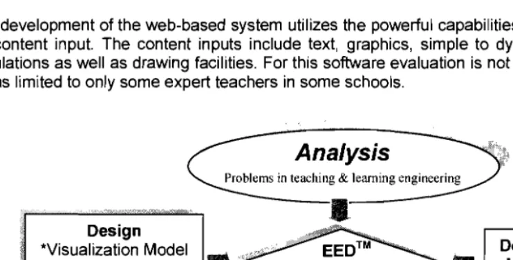
Figure 1: Development model Design
*Visualization Model
I_
*Electronic Drawing .
Board Program
•
OPEN
UNIVEPS
MALAVSIA
The development of the web-based system utilizes the powerful capabilities of Macromedia Flash for content input. The content inputs include text, graphics, simple to dynamic animations and simulations as well as drawing facilities. For this software evaluation is not done very extensively. It was limited to only some expert teachers in some schools.
The design of the software has considered the following design interface:
1. Ease of use. Untrained students or teachers can easily use the courseware.
2. Allow students to visualize drawing in 3-dimensional. Student can explore an oblique in
3D form from top view, front view and side view (Figure 2).
3. Engineering drawing built to scale.
4. Use it anytime as many times needed. Users can learn anywhere, anytime and any
place.
DESIGN AND DEVELOPMENT OF THE SYSTEM
From a fundamental understanding of the strengths and weaknesses, abilities and limitation, and basic functional mechanisms of the human visual system, the use of technology may be able to solve this problem by integrating pedagogy and technology into the teaching-learning process. By using the constructivist model students maybe able to construct and apply the concepts into real life situation (Widad & Rio, 2004) with the help of technology.
For the EED™ courseware, the design and development was based on the Visualisation Model and the Constructivist Model as shown in Figure 1. The instructional design (ID) model was
based on basic ID components such as analysis, design, development and evaluation. In the
analysis stage problems in teaching and learning engineering drawings were analysed in order to provide appropriate solutions to the problems. For example if the student is unable to visualize the real object the software will provide three different views to aid their visualisation capability. In the design stage, the correct teachingllearning strategies were integrated into the design of the web-based system. The constructivist Needham model incorporating elicitation of ideas, reconstruction of ideas, application and reflection was applied as the teachingllearning strategy.
~,'iVlHr;A';.l A$,*,A$.~X~:\..flQl.i f(Y>l; :N.S:UW,*"~Ri:=:-SfJ.Jl:'C,'"l
~
SEil\IR
E-i:.
~
<). ..
~,.:
..:. ,:/
-;
. ' "P... - :
c) Isometric Using the Frame Method
f) Auxiliary View
.:'IF·
j; /-~
"
a
e) Oblique
b) Isometric Using the Box Method
Figure 2: Visualisation of an object from 3 views
•
~f~~I!r~~)X~K~SIT"{
THE 6TH SEAAIR ANNUAL CONFERENCE; Langkawi, September 5 - 7 2006
Some Innovations
This innovative E-Engineering Drawing (EED™) developed (patented to Rio & Widad, 2004) has some novel features as follows:
1. Based on research studies of Engineering Drawing problems.
2. Incorporating the Visualisation-Constructivist Model.
3. Drawing Facilities.
4. E-Visualisation Test.
5. Graphics of Engineering Drawing objects. 6. Animations of objects in different angles. 7. Animations from various projection views. 8. Transfer of dimension from objects to drawings. 9. A web-based system.
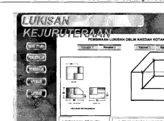
Figure 3 is a snapshot of EED™ user interface. The courseware provides the visualisation environment that could overcome students' difficulties in visualisation. The system could also assist
teachers explain engineerin~ drawing in 3-D thus maximising the students' learning. The use of
visualisation engine in EEDT aims to sharpen and enhance the students' visualisation skills.
~
•
~PEN
U
~lIVERSITY
SEA\IR
$~)l,.f1H!;;:,o\,>~~".#fA.~X:l4ri¢N
THE 6TH SEAAIR ANNUAL CONFERENCE; Langkawi, September 5 -7 2006 F(~t/'lis.!rHrrt(.~R~Sf~
E-ENGINEERING DRAWING (EED™)
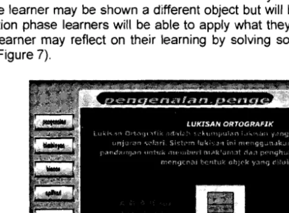
The courseware was designed for Form 4 and Form 5 students from Academic Schools &
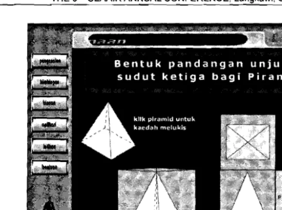
Technical Schools, as well as those from colleges, Mara Skill Institute, IPTA, IPTS, and the general public in learning Engineering Drawing. Topics in EEO™ are Isometric, Orthographic, Oblique, Rotation, and Auxiliary View. Learning Engineering Orawing using EEO™ begins with the user Ileamer selecting the topics they wish to explore. The learners are then channelled to the orientation phase (Figure 4). In this phase the learner will be able to learn the concepts of any particular topic. For example learners will be taught concepts of orthographic third angles by simulations of different views of the object given (Figure 5). After the orientation phase, learners will be given an environment where their ideas about concepts that they had learn in the orientation phase were elicited. The elicitation of ideas may be in the form of problem solving. For example the learner may be shown a different object but will be tested on the same concepts. In the application phase learners will be able to apply what they learn to new situations (Figure 6). Lastly the learner may reflect on their learning by solving some given problems or via problem scenarios (Figure 7).
\
i
:8f)f.)'f"le:A:'il A~"J<:4:ll::¥.)('-::411£fN
rCA ;N.Sr,TU'f!"~.Rf.AAAA{:H
~
SE£IR
De
Be
Latlhan
ce
AeA
Figure 6: Application phase
Figure 7: Reflection Berpandukan rajah sukuan satah dl sebelah, antara berlkut yang manakah bentuk sukuan satah sudut k@tiga 1
Figure 5: Simulations of different views of the object
•
~;~~IT~~;~~~S!TY
~v,)\" , f ' , ,1/\--Alb
...
~...
Ii
"·"c·'loIA
• l v l f , '. ".' . ,}
SOOR
s-t.".'\f'1'''' t!<ST l<,$N~M$(x.,ll11.T<rJN
THE 6TH SEAAIR ANNUAL CONFERENCE; Langkawi, September 5 - 7 2006 Fr.* IIt$-!ll\j1'Il'«l1l. Rf~-H
SUMMARY
This paper had discussed the general design and development concepts behind EEDTM. The
design and development of the web-based system has taken into consideration both pedagogical and as well as technological aspects. The instructional design theory was used to guide the development process so as to achieve the desired product
ACKNOWLEDGEMENTS
We would like to sincerely thank the many individuals who contributed towards the research. We are pleased to acknowledge the support of Armanizam Bin Mohamad Pon, Fadzly Fadzil Bin Abdul Rahim, Jabdullah bin Hassan, Janain Bin Burut, Mike Jackson Akong, Mohd Fadhil Abdulla
@ Frederick Josue, Mohd Helme Bin Supaat, Roshaizat Bin Abdul Kadir, Razali Bin Mistam, and Zulkifli Bin Ismail for their contribution in the development of this system. The authors also gratefully acknowledge the financial support of the BIP, Universiti Teknologi Malaysia for the grant awarded to conduct this research.
REFERENCES
Chalmers, A., & Cater, K. (2005). Exploiting human visual perception in visualisation. In Hansen, C. D., & Johnson, C. R. (Ed.) The Visualisation Handbook. Amsterdam, Boston, Heidelberg, London, New York, Oxford, Paris, San Diego, San Francisco, Singpore, Sydney and Tokyo: Elsevier Butterworth-Heinemann.
Jayasree Jayadevan. (2003). Keberkesanan grafik komputer dan latihan kemahiran spatial ke
atas pelajar lukisan kejuruteraan-satu kajian kes. Universiti Teknologi Malaysia: Master
Thesis.
Santos, E. D., Yee, Cheng L., & Petreche, J. R. D. (1998). An On-line Interactive Tutorial on Projective Geometry. Proceeding of
8
h International Conference On Engineering ComputerGraphics and Descriptive Geometry pada 31 July - 3 August 1998. USAICECGDG.
Sorby, S. A. (2001). Improving the spatial skills of engineering students: Impact on graphics performance and retention. Engineering Design Graphics Journal, 65(3), pp. 31-36.
Widad Othman & Adnan Ahmad. (2000). Teachers thinking style in solving engineering drawing problems. Proceeding at "International Conference On Technical & Vocational Education" on 21 - 23 Nov. 2000. Petaling Jaya: Institut Teknologi Tun Hussein ann & Teknikal Education Department, Ministry Of Education Malaysia.
Widad Othman & Rio Sumarni. (2004). E-engineering drawing - A web based system for teaching and learning engineering draWing. Abstrak Produk dIm "15th International
Invention, Innovation, Industrial Design and Technology Exhibition" pada 20 - 22 Mei 2004.