December, 1995
Intuity Integration with
System 75 and DEFINITY
Communications System
Generic 1 and Generic 3
Graphics ©
Issue 4 December 1995
iii
Table of Contents
iAbout This Book
xi■ Purpose xi
■ Intended Audience xi
■ How This Document Is Organized xii
■ Conventions Used xiii
■ Trademarks and Service Marks xiv
■ How to Make Comments About This Book xvi
1
Switch Integration Requirements
1-1■ An Introduction to Switch Integration and DCIU 1-2 ■ Switch Releases Supported by the Intuity System 1-3
■ GPSC/AT/E 1-4
■ SN229 Circuits — Do Not Use 1-4
■ Intuity System Switch Connections 1-4
Connections through an IDI 1-4
Hardware Required for the Connection 1-5
Connections through an MPDM 1-8
Hardware Required for the Connection 1-8
2
Switch Integration Planning
2-1Section 1: MPDM Information 2-10
Section 2: Processor Interface Data Link
Information 2-11
Section 3: Processor Channel and Interface Data
Link Information 2-12
Section 1: BX.25 Data Module Information 2-14 Section 2: Interface Link and Processor
■ DCS Worksheets 2-18
3
System 75 and DEFINITY Generic 1
Administration
3-1■ Administer the Voice Ports as Stations 3-2
Create a Unique COR 3-2
Create a Unique COS 3-3
Administer the First Voice Port 3-4
Duplicate the Station 3-7
■ Assign the Hunt Group 3-8
■ Assign the Data Link 3-13
Assign the MPDM 3-14
Assign the Processor Interface Data Module 3-16
Assign the Interface Link 3-18
Assign the Processor Channel 3-21
Verify the Link 3-23
4
DEFINITY G3r Administration
4-1■ Assign User Defined Adjunct Names 4-2
■ Administer the Voice Port Stations 4-3
Create a Unique COR 4-3
Create a Unique COS 4-4
Administer the First Voice Port Station 4-5
Duplicate the Station 4-8
■ Assign the Hunt Group 4-9
■ Assign the Data Link 4-16
Administer the Packet Gateway Board 4-17
Assign the BX.25 Data Module 4-18
Assign the Interface Link 4-23
Issue 4 December 1995
v
5
DEFINITY G3i, G3i-Global, G3s, and
G3vs Administration
5-1■ Administer the Voice Port Stations 5-2
Create a Unique COR 5-2
Create a Unique COS 5-3
Administer the First Voice Port 5-4
Duplicate the Station 5-7
■ Assign the Hunt Group 5-8
■ Assign the Data Link 5-13
Assign the MPDM 5-14
Assign the Processor Interface Data Module 5-17
Assign the Interface Link 5-19
Assign the Processor Channel 5-22
Verify the Link 5-24
6
DCS Administration
6-1■ DCS Description 6-2
An Intuity System in a DCS Configuration Using
BX.25 Data Channels 6-3
An Intuity System in a DCS Configuration Using ISDN-PRI D-Channel (DEFINITY G3i, G3r, G3s,
and G3vs only) 6-3
Example DCS Solution 6-4
Connectivity 6-4
■ System 75 and DEFINITY G1 DCS Administration 6-6 Assign the Processor Channel at the Remote
Switch 6-7
Disable the Host to Remote Switch DCS Link 6-8
Administer the Processor Channel 6-9
Enable the Host to Remote Switch DCS Link 6-12
Assign the Hop Channel 6-12
Busyout the Host to Remote Switch DCS Link
and the Host-to-Intuity System Link 6-16 Assign the Hunt Group at the Remote Switch 6-16
■ G3r DCS Administration 6-19
Assign User Defined Adjunct Names 6-21
DCS with BX.25 Signaling Administration 6-22 Assign the Processor Channel at the
Remote Switch 6-23
Disable the Host to Remote Switch DCS Link 6-23 Administer the Processor Channel 6-24 Enable the Host to Remote Switch DCS Link 6-27
Assign the Hop Channel 6-28
Busyout the Host-to-Remote Switch DCS Link and the Host-to-Intuity System Link 6-28 Administer the Hop Channel Assignment
Screen 6-29
Release the Host-to-Remote Switch DCS Link and the Host-to-Intuity System Link 6-31 DCS Via ISDN-PRI D-Channel Administration 6-31
Assign the Processor Channel at the Host Switch DCS6-32
Assign the Signaling Group at the Host Switch 6-34 Assign the ISDN TSC Gateway Channel at the Host
Switch 6-40
Administer DCS through ISDN-PRI at the
Remote Switch 6-42
Assign the Hunt Group at the Remote Switch 6-47
■ G3i, G3s, G3vs DCS Administration 6-51
DCS with BX.25 Signaling Administration 6-54 Assign the Processor Channel at the
Remote Switch 6-55
Busyout the Host-to-Remote Switch DCS Link 6-55 Administer the Processor Channel 6-56 Release the Host-to-Remote Switch DCS Link 6-59 Assign the Hop Channel at the
Host Switch 6-60
Issue 4 December 1995
vii
Screen 6-60
Release the Host-to-Remote Switch DCS Link and the Host-to-Intuity System Link 6-63 DCS Via ISDN-PRI D-Channel Administration 6-63
Assign the Processor Channel at the
Host Switch DCS 6-64
Assign the Signaling Group at the Host Switch 6-66 Assign the ISDN TSC Gateway Channel at the Host
Switch 6-73
Administer DCS through ISDN-PRI at the
Remote Switch 6-75
Assign the Hunt Group at the Remote Switch 6-81 ■ Administer the Subscribers (Remote Switch) 6-84
Assign the Call Coverage Path for Subscribers
(Remote Switch) 6-85
Modify the Station Screen for Each Remote
Subscriber 6-88
7
Intuity System Administration for
Switch Integration
7-1■ Administer the Intuity System for a
Non-DCS Switch Integration 7-1
■ Administer the Intuity System for a
DCS Network Switch Integration 7-5
Administer the DCS Network Time Zone 7-7
■ Changing the Switch Extension Length
on the Intuity System 7-8
Change the Intuity System Settings 7-8
Stopping and Starting the Voice System 7-10
8
Acceptance Test Administration
8-1■ Acceptance Test Procedures 8-2
Assign the Call Coverage Path for the
Test Subscribers 8-2
9
Cut-to-Service Administration
9-1■ Cut-to-Service Procedures 9-2
Assign the Call Coverage Path for Subscribers 9-2 Modify the Station Screen for Each Subscriber 9-5
10
Optional Switch Administration for
Intuity System Features
10-1■ Intuity AUDIX Digital Networking
Package Switch Administration 10-1
Configure the Data Module 10-2
Create a Hunt Group 10-3
■ Automated Attendant Administration 10-5
Assign a Station 10-5
Assign a Hunt Group 10-5
■ Night Service to Automated Attendant Administration 10-6
From Incoming Trunk Administration 10-6
From Listed Directory Number (LDN) 10-7
■ Automated Attendant Substitute Strategies 10-7
■ Transfer into Intuity 10-8
■ Switch Recorded Announcement 10-8
■ Switch Multiple Coverage Paths 10-9
A
Security
A-1■ Protecting Your Voice/Fax Messaging System A-1
Voice Messaging A-2
Automated Attendant A-2
■ MERLIN LEGEND Switch Administration A-2
Restrict Outward Dialing A-3
Restrict Toll Areas A-3
Issue 4 December 1995
ix
■ Switch Administration A-3
Restrict Outward Dialing A-4
Assign Low Facilities Restriction Level (FRL) A-4
Restrict Toll Areas A-6
Block Subscriber Use of Trunk Access Codes
(G2, System 85 Only) A-8
Create Restricted Number Lists (G1, G3, and
System 75 Only) A-8
Create Allowed and Disallowed Number Lists
(MERLIN LEGEND Only) A-8
Restrict AMIS Networking Number Ranges A-8
■ Subscriber Password Guidelines A-9
■ Intuity AUDIX Administration A-10
Mailbox Administration A-10
Outcalling A-10
Basic Call Transfer (5ESS, DMS-100, MERLIN
LEGEND, and Non-AT&T Switches) A-11
Enhanced Call Transfer (System 75, System 85,
G1, G2, G3) A-12
Intuity FAX Messaging A-12
■ Detecting Voice Mail Fraud A-13
Call Detail Recording (or SMDR) A-13
Call Traffic Report A-14
Trunk Group Report A-15
SAT, Manager I, and G3-MT Reporting A-15
ARS Measurement Selection A-15
Automatic Circuit Assurance A-16
Busy Verification A-17
AUDIX Traffic Reports A-17
■ AT&T’s Statement of Direction A-18
AT&T Security Offerings A-19
AT&T Toll Fraud Crisis Intervention A-20
B
Switch Administration for INTUITY Lodging
B-1■ Hunt Group Administration B-1
■ Message Retrieval Administration B-1
Message Retrieval in Lodging Systems without
AUDIX B-2
Message Retrieval in Systems Shared with AUDIX B-2 Retrieval from the AUDIX Ap plication B-2 Retrieval from the Lodging Ap plication B-2
Alternate Message Retrieval Method B-2
■ Voice Mail Administration B-3
■ Call Coverage Path B-4
■ Do Not Disturb B-4
■ Cut to Service B-5
Gradual Cut to Service B-5
One-Step Cut to Service B-5
ABB
Abbreviations
ABB-1GL
Glossary
GL-1Issue 4 December 1995 xi
Purpose
This document, Intuity Integration with System 75 and DEFINITY
Communications System Generic 1 and Generic 3, 585-310-214, contains the procedures required to administer a System 75, DEFINITY® Communications System Generic 1 (G1), Generic 3i (G3i), Generic 3r (G3r), Generic 3s (G3s), and Generic 3vs (G3vs) to integrate with an Intuity system.
Intended Audience
■ "About This Book"
This preface describes the document’s purpose, intended audiences, organization, conventions, trademarks and service marks, and related resources. This preface also explains how to make comments about the document.
■ Chapter 1, "Switch Integration Requirements"
This chapter contains information that explains switch integration
processes, terms, and requirements includes an introduction to the switch integration process, a section on switches supported by the Intuity system, configuration descriptions that explain each of the integration hardware components, and configuration diagrams that show you the different hardware, physical connections, and cables used to connect the Intuity system and the switch
■ Chapter 2, "Switch Integration Planning"
This chapter contains worksheets that must be completed before performing the switch administration. The worksheets allows you to completely plan the integration.
■ Chapter 3, "System 75 and DEFINITY Generic 1 Administration" This chapter contains procedures for administering a System 75 or DEFINITY G1 switch for integration with the Intuity system.
■ Chapter 4, "DEFINITY G3r Administration"
This chapter contains procedures for administering a DEFINITY G3r switch for integration with the Intuity system.
■ Chapter 5, "DEFINITY G3i, G3i-Global, G3s, and G3vs Administration" This chapter contains procedures for administering a DEFINITY G3i, G3i-Global, G3s, and G3vs switch for integration with the Intuity system.
■ Chapter 6, "DCS Administration"
This chapter contains procedures for administering a Distributed Communications System (DCS) switch network with an Intuity system. The Intuity system can serve more than one switch when the switches are part of a DCS network.
-xiii
Issue 4 December 1995 xiii
tests for the Intuity system.■ Chapter 9, "Cut-to-Service Administration"
This chapter explains how to administer the switch for the Intuity system cut-to-service process. Cutting over an Intuity system requires you to change the coverage path used by all subscribers. Performing a cut-to-service provides all subscribers with voice messaging cut-to-services.
■ Chapter 10, "Optional Switch Administration for Intuity System Features" This chapter contains procedures required to administer the switch to operate with the optional features of the Intuity system such as AUDIX® Digital Networking, AMIS Analog Networking, Intuity Voice Response, and Automated Attendant.
■ Appendix A, "Security"
This appendix provides important information for securing the system against telecommunications fraud. Review the information in this appendix before starting the switch integration process.
■ Abbreviations
This section provides a list of abbreviations and acronyms used in Intuity Voice Processing documentation.
■ Glossary
The Glossary provides a definition of terms and acronyms used in Intuity system documentation.
■ Index
The Index provides an alphabetical listing of principal subjects covered in this document.
Conventions Used
The following conventions were used in this document:
■ Rounded boxes represent keyboard keys that you press. For example, an instruction to press the enter key is shown as Press .
■ Square boxes represent phone pad keys that you press.
For example, an instruction to press zero on the phone pad is shown as Press .
■ The word “enter” means to type a value and press . ENTER
0
■ Two or three keys that you press at the same time (that is, you hold down the first key while pressing the second and/or third key) are shown as a rounded box that contains two or more words separated by hyphens. For example, an instruction to press and hold while typing the letter d is shown as
Press
■ Commands and text you type or enter appear in bold.
■ Values, instructions, and prompts that you see on the screen appear as
follows: Press any key to continue.
■ Variables that the system supplies or that you must supply appear in italics.
For example, an error message including one of your file names appears as
The file filename is formatted incorrect.
Trademarks and Service Marks
The following trademarked products are mentioned in the books in the INTUITY library:
■ AT™ is a trademark of Hayes Microcomputer Products, Inc.
■ AUDIX® is a registered trademark of AT&T.
■ BT-542B™ is a trademark of BusLogic Inc.
■ COMSPHERE® is a registered trademark of AT&T Paradyne Corp.
■ CONVERSANT® is a registered trademark of AT&T.
■ DEFINITY® is a registered trademark of AT&T in the U.S. and throughout the world.
■ Dterm™ is a trademark of NEC Telephones, Inc.
■ Equinox™ is a trademark of Equinox Systems, Inc.
■ 5ESS® is a registered trademark of AT&T.
■ INTUITY™ is a trademark of AT&T.
■ MD110® is a registered trademark of Ericsson, Inc.
■ MEGAPLEX™ is a trademark of Equinox System, Inc.
■ MEGAPORT™ is a trademark of Equinox Systems, Inc. ALT
-xv
Issue 4 December 1995 xv
Inc.■ Microsoft® is a registered trademark of Microsoft Corporation.
■ MS® is a registered trademark of Microsoft Corporation.
■ MS-DOS® is a registered trademark of Microsoft Corporation.
■ NEAX™ is a trademark of NEC Telephone, Inc.
■ NEC® is a registered trademark of NEC Telephones, Inc.
■ Netware® is a registered trademark of Novell, Inc.
■ Netware® Loadable Module™ is a trademark of Novell, Inc. ■ NLM® is a registered trademark of Novell, Inc.
■ Northern Telecom® is a registered trademark of Northern Telecom
Limited.
■ Novell® is a registered trademark of Novell, Inc. ■ ORACLE™ is a trademark of Oracle Corporation. ■ Paradyne® is a registered trademark of AT&T.
■ Phillips® is a registered trademark of Phillips Screw Company. ■ Rolm® is a registered trademark of International Businss Machines. ■ SL-1™ is a trademark of Northern Telecom Limited.
■ softFAX® is a registered trademark of VOXEM, Inc. ■ TMI™ is a trademark of Texas Micro Systems, Inc.
■ UNIX® is a registered trademark of Novell in the United States and other
countries, licensed exclusively through X/Open Company Limited.
A reader comment card is behind the title page of this document. While we have tried to make this document fit your needs, we are interested in your suggestions for improving it and urge you to complete and return a reader comment card. If the reader comment card has been removed, send your comments to:
AT&T
Product Documentation Development Department Room 22-2C11
11900 North Pecos Street Denver, Colorado 80234
Issue 4 December 1995 1-1
1
This chapter contains information that explains switch integration processes, terms, and requirements including:
■ An introduction to switch integration that provides you with a brief explanation of the switch integration processes
■ An explanation of the switches supported by the Intuitysystem
■ Configuration descriptions that explain each of the components required to establish a link with the switch
■ Configuration diagrams that show you the different hardware, physical connections, and cables used to connect the Intuity system and the switch
An Introduction to Switch Integration
and DCIU
Switch integration refers to the sharing of information between a voice
messaging system and a switch to provide a seamless interface to callers and subscribers. A fully integrated voice messaging system answers calls with information taken directly from the switch.
To create an integrated environment for the Intuity system and an AT&T System 75, DEFINITYCommunication System Generic 1 (G1), Generic 3i (G3i), Generic 3r (G3r), Generic 3s (G3s), or Generic 3vs (G3vs) switch, the system uses a Digital Communications Interface Unit (DCIU) link to the switch. The DCIU link transfers digital call information, such as called party and calling party
information, to the Intuity system. The system exchanges analog voice
information with the switch through analog telephone lines. DCIU is also referred to as Switch Communication Interface (SCI) or the Processor Interface (PI).
DCIU acts as a processor with nine physical channels. One of the channels connects to the switch processor. The remaining eight channels can connect to external processors, such as an Intuity system, an AUDIX system, another switch on a Distributed Communications System (DCS), or a Call Management System (CMS). Each of the DCIU physical links can have multiple logical channels, with a maximum of 64 channels. The 64 channels can be distributed to the external adjuncts using various methods. For example, if you have an Intuity system and a DCS network, you could use 48 of the channels for the Intuity system and 16 of the channels for the DCS network.
When integrated through a DCIU link, the Intuity system sends message packets to the switch using the BX.25 protocol at 9.6 Kb ps. The messages received by the DCIU from the Intuity system can be routed to something else, such as the host switch, or they can be routed on another outgoing channel. This processing power allows a remote switch on a DCS, a host switch, and an Intuity system to work together.
DCIU serves as a message router or a multiplexer, receiving information on one side and sending the information out to various places, because DCIU routes or
hops messages from the Intuity system to switch.
Issue 4 December 1995 1-3
Switch Releases Supported by the
Intuity System
The Intuity system supports several AT&T switches (also called Private Branch Exchanges or PBXs). Table 1-1 shows you the supported switches and required software releases.
Table 1-1. Intuity System Supported Switches
NOTE
:
System 75 and DEFINITY G1 and Version 1 of DEFINITY G3i, G3s, and G3vs switches do not support two I-Channels per port for Intuity AUDIX Digital Networking. Version 2 and above of DEFINITY G3i, G3s, and G3vs do support two I-Channels as a purchasable option.
Switch Release
System 75 Release 1, version 3, issue 1.7 and above. The System 75 switch must contain a Processor Interface (PI) card. Some early versions of the System 75 R1V3, models 1A, 1B, 2A, and 2B carriers, may not support the PI board complex required with the Intuity system. These carriers may not have a PI/EIA port for IDI connectivity and you must use the MPDM option.
DEFINITY Generic 1 All
DEFINITY Generic 3i All
DEFINITY Generic 3r All
DEFINITY Generic 3s All
DEFINITY Generic 3vs All
DEFINITY G2 All: For information on the DEFINTIY G2 switch, refer to Intuity System Integration with System 85 and DEFINITY Generic 2 Communications Systems, 585-310-215
GPSC/AT/E
For all AT&T switch integrations with an Intuity system, a general-purpose synchronous controller AT-enhanced (GPSC/AT/E) card is required. The GPSC card communicates with the switch through the DCIU link and transfers digital call information. For GPSC card installation instructions, refer toone of the following documents:
■ Intuity MAP/40 Hardware Installation, 585-310-138
■ Intuity MAP/100 Hardware Installation, 585-310-139
SN229 Circuits — Do Not Use
Do not connect Intuity voice ports to SN229 circuits in DEFINITY switches. The SN229 circuits do not provide the positive disconnect that the Intuity system uses for outcalling and AMIS Analog Networking.
Instead, connect to TN754B or SN228B circuits. If you are using SN228B circuits on the DEFINITY switch, use the following settings:
■ Program the station as on-prem.
■ Set the board to 600 Ω low gain. (The board ships from the factory with a setting of 600 Ω high gain. This setting is too high for use with Intuity voice ports and often causes echo.)
Intuity System Switch Connections
Use the information and diagrams in this section to understand the different configurations for connecting an Intuity system with a System 75, DEFINITY G1, G3i, G3r, G3s, and G3vs. You can use the following methods to connect to the switch:
■ Isolating Data Interface (IDI) connections
■ Modular Processor Data Module (MPDM) connections
Read the configuration information to determine the best connection for your system.
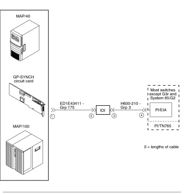
Connections through an IDI
Issue 4 December 1995 1-5
The maximum length between an Intuity system GP-Sync card and an IDI is 15 meters (50 feet). This limitation applies only to the distance between the GP-Sync card and the IDI and does not affect or include the distance between the IDI and the switch. (This distance is separately covered in the switchdocuments). If the Intuity MAP and the switch must be more than 15 meters (50 feet) apart, use an MPDM to facilitate the connection. Refer to the next section, "Connections through an MPDM", for information on MPDM connectivity.
Hardware Required for the Connection
■ One IDI
■ One ED-1E43411-Group 175 cable
■ One H600-210, Group 1 through 7. The group depends on cable length.
Figure 1-1. System 75, G1, G3i, G3s, and G3vs IDI Connection to the Switch
n
Issue 4 December 1995 1-7
Figure 1-2. DEFINITY G3r IDI Connection to the Switch
Connections through an MPDM
Use an MPDM to connect an Intuity platform to a switch that is located more than 15 meters (50 feet) away. For a local or closely located Intuity platform and switch, use an IDI as described in "Connections through an IDI". Figure 1-3 and Figure 1-4 show you the connections for the System 75, DEFINITY G1, G3i, G3r, G3s, and G3vs. Study the diagrams to understand the connections.
Hardware Required for the Connection
■ One MPDM with an RS-232C interface card
■ One ED-1E434-1I Group 110 cable (comcode 524124658)
■ One 25-pair cable (connects the TN754 to the cross-connect field)
■ One D8W-57 4-pair module cord
■ One 103A adapter with 3-pair cord
■ For a DEFINITY G3r only:
— A second 25-pair cable (connects the second TN754 to the cross-connect field)
— A second D8W-57 4-pair modular cord — A second 103A adapter with a 3-pair cord — A second MPDM with an RS-232C interface card — One M25A 50-foot RS-232C male-to-female cable
Issue 4 December 1995 1-9
Issue 4 December 1995 2-1
2
Before you integrate the Intuity system with a switch, you must plan the process. This chapter provides worksheets and information to help you plan and record the integration. You use the worksheets later to complete the switch integration process. The planning and worksheets in this chapter must be completed before the Intuity system is installed. This chapter includes worksheets to collect the following information:
■ Voice port information
■ Local and remote switch hunt group information
■ Remote and local data link information
■ Call coverage assignments
■ Hop channel assignments
■ Remote and host ISDN information
Worksheet A: Voice Port Station
Information
Complete the information on this worksheet to collect information required to administer the Intuity system voice ports on the switch.
Date:
Prepared By:
Contact Telephone Number:
Field Recommended Your Entry
User Defined Adjunct Names (G3r only)
Record the name you plan to use for the Intuity system on the User Defined Adjunct Names form. You can enter a maximum of seven characters.
Extension Complete Worksheet B:
Voice Port Extensions and Names
Type System 75, DEFINITY G1,
G3i, G3i-Global, G3r, G3s, and G3vs: 2500
Port Complete Worksheet B:
Voice Port Extensions and Names
Name Complete Worksheet B:
Voice Port Extensions and Names
Lock Messages n
Issue 4 December 1995 2-3
Class of Restriction (COR)To prevent toll fraud, AT&T recommends that you create a COR for voice ports that allows subscribers to call only other numbers with the same COR. If you later decide that subscribers need to call numbers with different CORs, add permissions for the other CORs one at a time. The AMIS Analog Networking, Message Delivery, and Outcalling features require the ability to call numbers with different CORs.
Class of Service (COS)
Create a COS for the voice ports that permits the Data Privacy feature. AT&T recommends that you do not enable any other features on the COS.
Tests n
LWC Reception All switches: audix
Headset (System 75 and DEFINITY G1 only)
n
LWC Activation n
SMDR (CDR) Privacy (Not available on System 75 or G1)
n
Redirect Notification n
Off Premise Station n
Coverage Message Retrieval n
Auto Answer n
Data Restriction n
Call Waiting Indication n
Att. Call Waiting Indication (Not avail-able on System 75 or G1)
n
Distinctive Audible Alert n
Message Waiting Indicator blank blank
Adjunct Supervision (G3i/s only) y
R Balance Network (Not available on System 75 or G1)
n
Switchhook Flash y
Message Server Name (G3r only) blank blank
Audible Message Waiting (G3r only) n
Issue 4 December 1995 2-5
Worksheet B: Voice Port Extensions
and Names
Enter the location, name, and extension for each of the purchased (maximum of 64) voice ports in the following worksheet.
Date:
Prepared By:
Contact Telephone Number:
Intuity Port
Analog Port Equipment
Location1 Name2 Extension
1 AUDIX 1
2 AUDIX 2
3 AUDIX 3
4 AUDIX 4
5 AUDIX 5
6 AUDIX 6
7 AUDIX 7
8 AUDIX 8
9 AUDIX 9
10 AUDIX 10
11 AUDIX 11
12 AUDIX 12
13 AUDIX 13
14 AUDIX 14
15 AUDIX 15
16 AUDIX 16
17 AUDIX 17
19 AUDIX 19
20 AUDIX 20
21 AUDIX 21
22 AUDIX 22
23 AUDIX 23
24 AUDIX 24
25 AUDIX 25
26 AUDIX 26
27 AUDIX 27
28 AUDIX 28
29 AUDIX 29
30 AUDIX 30
31 AUDIX 31
32 AUDIX 32
33 AUDIX 33
34 AUDIX 34
35 AUDIX 35
36 AUDIX 36
37 AUDIX 37
38 AUDIX 38
39 AUDIX 39
40 AUDIX 40
41 AUDIX 41
42 AUDIX 42
43 AUDIX 43
44 AUDIX 44
45 AUDIX 45
46 AUDIX 46
Intuity Port
Analog Port Equipment
Issue 4 December 1995 2-7
1. For System 75, the equipment location is a 5-character identifier; the first character identifies the carrier, the 2nd and 3rd characters identify the slot number, and the 4th and 5th characters identify the port number. As an example, a valid location for System 75 is B0701: carrier B, slot 07, and port 01. For all other switches, an additional 1 or 2 digits is added to the carrier, slot, and port location to identify the cabinet. For example, the location 02B0701 specifies cabinet 02, carrier B, slot 07, port 01.
2. These are the recommended names.
47 AUDIX 47
48 AUDIX 48
49 AUDIX 49
50 AUDIX 50
51 AUDIX 51
52 AUDIX 52
53 AUDIX 53
54 AUDIX 54
55 AUDIX 55
56 AUDIX 56
57 AUDIX 57
58 AUDIX 58
59 AUDIX 59
60 AUDIX 60
61 AUDIX 61
62 AUDIX 62
63 AUDIX 63
64 AUDIX 64
Intuity Port
Analog Port Equipment
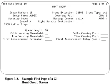
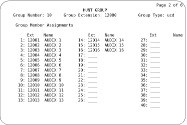
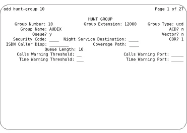
Worksheet C: Assign the Hunt Group
The following information is required to define a hunt group (containing the voice port members) for the Intuity system voice ports.
NOTE
:
Only the number of ports actually purchased should be administered in the hunt group
Date:
Prepared By:
Contact Telephone Number:
Field Recommended Your Entry
Group Number:
Enter the number you would like to use to identify the Intuity hunt group. This number, preceded by an h, is entered in the voice port Coverage Path form and in subscriber coverage paths.
Group Extension
Enter the extension number you want subscribers to dial to retrieve their messages from the Intuity system.
Group Type ucd
Group Name
Enter the name you would like to appear on display sets when subscribers call the Intuity system. AUDIX must be included in the name for G3-MA to recognize the name as an Intuity group.
Message Center audix
ACD n
Queue y
Night Service Destination leave blank leave blank
Vector (y/n)?
Issue 4 December 1995 2-9
Security Code leave blank leave blank
Coverage Path leave blank leave blank
COR
Enter the Class of Restriction (COR) you would like assigned to the extension that subscribers will call to reach the Intuity system. For security reasons, AUDIX and Lodging hunt groups should be assigned their own CORs which have been restricted from accessing all outgoing trunks or only those trunks needed for Outcalling or AMIS Analog Networking. The default COR is not recommended.
ISDN Call Disp (not available on System 75 and G1)
If ISDN-PRI is enabled, enter grp-name or mbr-name to specify whether the hunt group name or number is sent to the originating subscriber.
AUDIX Extension (System 75 R1V3 only)
This field appears only on a remote switch in a DCS network when message center is active.
The field refers to the host switch Intuity extension number. This is the number the remote Intuity users will dial to access the hunt group. Normally this field is left blank for the Intuity system.
Queue Length
A suggested length is the number of configured Intuity voice ports.
Calls Warning Threshold leave blank leave blank
Calls Warning Port leave blank leave blank
Time Warning Threshold leave blank leave blank
Time Warning Port leave blank leave blank
First Announcement Extension (n/a for G3r)
If you want a switch-recorded announcement, enter the extension number here.
First Announcement Delay (sec) (n/a for G3r)
Optional if the queue is y – must be blank if there is no first announcement.
Worksheet D: Assign the Data Link
for
System 75, DEFINITY G1, G3i,
G3i-Global, G3s, and G3vs Switches
Use this worksheet to plan the data link for a System 75, DEFINITY G1, G3i, G3i-Global, G3s, or G3vs switch. If you have a DEFINITY G3r switch, proceed to
Worksheet E: Assign the Data Link for a DEFINITY G3r Switch.
Date:
Prepared By:
Contact Telephone Number:
Section 1: MPDM Information
Complete the following section of the worksheet only if you plan to use an MPDM and a TN754 digital line port to connect the Intuity system to the switch. If you do not have a connection through an MPDM, proceed to "Section 2: Processor Interface Data Link Information" of the worksheet.
Field Recommended Your Entry MPDM Data Module
Data Extension
Type pdm
Port
The port location for the TN754 that connects to the MPDM
Name
The data extension name for this port that identifies the Intuity system (perhaps audix or lodging)
COS See Worksheet
Issue 4 December 1995 2-11
Section 2: Processor Interface Data Link
Information
Complete the information in this section to assign the Processor Interface data link.
COR See Worksheet
A: Voice Port Station Information
Connected to dte
Remote Looparound Test n
Processor Interface Data Module
Field Recommended Your Entry
Data Extension
Type procr-infc (G1, G3i/s)
interface (System 75)
Physical Channel 01 if using the EIA port
02-04 if using an MPDM
If two PI circuit packs are installed, enter:
05-08 if using an MPDM
Name audix
COS See Worksheet A: Voice
Port Station Information
COR See Worksheet A: Voice
Port Station Information
Maintenance Extension
Section 3: Processor Channel and Interface Data
Link Information
Complete the information in this section of the worksheet to assign the Processor Channel and Interface data link.
Field Recommended Your Entry Processor Channel
Processor channel number Use the switch port
number on the Intuity Switch Administration
screen
Application audix
Interface Link Number
Enter the same number you entered for the physical channel in "Section 2: Processor Interface Data Link Information" of this worksheet.
Interface Channel Number
This field contains the logical channel number of the interface link. Use the same number entered in the
Logical Channel field on the Intuity System Switch Interface Administration screen.
Use 1 to 64. This field must match
the Remote Proc Chan field.
Priority h
Remote Proc Chan
This field contains the logical channel number of the interface link. Use the same number entered in the
Logical Channel field on the Intuity System Switch Interface Administration screen.
Use 1 to 64. This field must match the Interface
Channel Number field.
Machine-ID
This number must match the AUDIXNumber field on the Intuity Switch Interface Administration screen
Interface Link
Link
Enter the same number you entered for the physical channel in "Section 2: Processor Interface Data Link Information" of this worksheet.
Issue 4 December 1995 2-13
Est Conn y
Prot
Protocol type BX25 BX25
Destination Digits
Enter the MPDM extension if an MPDM is used or eia if link 1 is used with an IDI.
Destination Brd leave blank leave blank
DTE/DCE dte
Identification audix
Worksheet E: Assign the Data Link for
a DEFINITY G3r Switch
Use this worksheet to plan the data link for a DEFINITY G3r switch. If you have a System 75, DEFINITY G1, G3i, G3i-Global, G3s, or G3vs, proceed to Worksheet D: Assign the Data Link for System 75, DEFINITY G1, G3i, G3i-Global, G3s, and G3vs Switches.
Date:
Prepared By:
Contact Telephone Number:
Section 1: BX.25 Data Module Information
Complete the information in section to plan for assigning the BX.25 data module.
Field Recommended Your Entry
Name for the PGATE application
You can only change the information in this field when you add a PGATE card.
audix
PGATE card location
You can only change the information in this field when you add a PGATE card.
Type
You can only change the information in this field when you add a PGATE board.
BX.25
Port
Enter the PGATE port location to which the BX.25 data module connects.
Name
Enter the name that identifies the Intuity system connection
audix
COR
Endpoint Type adjunct
Issue 4 December 1995 2-15
Section 2: Interface Link and Processor
Channel Information
Complete the information in this section to plan the Interface Link and Processor Channel assignments.
Baud Rate 9600
Error Logging n
Remote Looparound Test n
Permanent Virtual Circuit
Highest PVC Logical Channel
Switched Virtual Circuit
Layer 2 Parameters
Number of Outstanding Frames 1
Retry Attempt Counter 2
Frame Size 135
Retransmission Timer (1/10 seconds) 10
Idle timer (1/10 seconds) 30
Layer 3 Parameters
Number of Outstanding Packets 2
Restart Timer (seconds) 8
Reset Timer (seconds) 180
Field Recommended Your Entry Interface Link
Link Number 1-8
Enabled y
BX.25 Extension
Enter the extension of the BX.25 data module.
Destination Number external
Establish connection blank blank
Connected Data Module blank blank
Identification
Enter the same name you entered in the User Defined Adjunct Name field on Worksheet A: Voice Port Station Information.
Processor Channel
Processor channel number 1-128
Application audix
Interface Link Number
Must be the same as the Link Number set above
Interface Channel Number
This field contains the logical channel number of the interface link. Use the same number entered in the
Logical Channel field on the Intuity System Switch Interface Administration screen.
This field must match the Remote
Port field.
Local Port
Use the same number entered in the Switch Port
field on the Intuity System Switch Interface Administration screen.
Remote Port
This field contains the logical channel number of the interface link. Use the same number entered in the
Logical Channel field on the Intuity System Switch Interface Administration screen.
This field must match the
Interface Channel Number field.
Adjunct Name
Enter the same name you entered in the User Defined Adjunct Name field on Worksheet A: Voice Port Station Information.
Machine-ID
Enter the Machine ID for the Intuity system. This number must agree with the AUDIX Number field on the Intuity Switch Interface Administration screen.
Issue 4 December 1995 2-17
Worksheet F: Assign the Call
Coverage
Path for Subscribers
Complete this worksheet to define call coverage paths for subscribers.
Date:
Prepared By:
Contact Telephone Number:
You have completed the worksheets and planning necessary for an Intuity system switch integration. If you do not have a DCS environment, proceed to the administration chapter for your switch. If you are placing an Intuity system in a
Field Recommended Your Entry
Coverage Path Number
Enter the number you want to identify the call coverage path for subscribers.
Next Path Number
If desired, enter the second path to which calls will be directed in case the current path fails.
Coverage Criteria
Station/Group Status Active? (Inside Call/ Outside Call)
y/y
Busy? (Inside Call/Outside Call) y/y
Don’t Answer? (Inside Call/Outside Call) y/y
All? (Inside Call/Outside Call) n/n
SAC/Go to Cover? (Inside Call/Outside Call) y/y
Number of rings
Enter the number of rings (1-99) you would like before a call goes to coverage.
3
Coverage Points
Issue 4 December 1995 2-19
DCS Worksheets
Complete worksheets G through P if the Intuity system operates in a DCS environment. If you have an existing DCS network or if you are installing one, the GBCS Design Center may have designed the DCS network for the Intuity system. The worksheets in this section contain the same information the Design Center may have already created. Use these worksheets to verify that you have all required information and as a single point of reference.
This section contains worksheets for both BX.25 signaling and ISDN signaling. If the DCS network uses BX.25 signaling, complete the following worksheets:
■ Worksheet G: Remote Non-G3r Processor Channel Assignment DCS BX.25 Signaling Information
■ Worksheet H: Remote G3r Processor Channel Assignment DCS BX.25 Signaling Information
■ Worksheet I: Host Hop Channel Assignment DCS BX.25 Signaling Information
■ Worksheet J: Assign the Remote Switch Hunt Group
■ Worksheet K: Assign the Call Coverage Path for DCS Remote Switches
If the DCS network uses ISDN signaling, complete the following worksheets:
■ Worksheet L: Non-G3r Host Processor Channel Assignment ISDN Gateway Information
■ Worksheet M: G3r Host Processor Channel Assignment ISDN Gateway Information
■ Worksheet N: HOST ISDN Signaling Group Information ■ Worksheet O: Remote ISDN Signaling Group Information ■ Worksheet P: Host ISDN TSC Gateway Channel Assignment
For each remote switch in the DCS network, complete one set of DCS
Worksheet G: Remote Non-G3r
Processor Channel Assignment DCS
BX.25 Signaling Information
Use this worksheet to plan the remote processor channels for a System 75, DEFINITY G1, G3i, G3i-Global, G3s, or G3vs switch. Complete one copy of this worksheet for each remote switch in the DCS network.
If you have a DEFINITY G3r switch, proceed to Worksheet H: Remote G3r Processor Channel Assignment DCS BX.25 Signaling Information.
Date:
Prepared By:
Contact Telephone Number:
Field Recommended Your Entry
Processor channel number 59, if available
Application audix
Interface Link Number
Enter the DCS link that connects this remote switch to the host switch.
Interface Channel Number
This field contains the logical channel number of the interface link. Use the number entered in the Logical Channel
field on the Intuity Switch Interface Administration screen that represents the node number of the switch.
This field must match the
Remote Proc Chan field.
Remote Proc Chan
This field contains the logical channel number of the interface link. Use the same number entered in the Logical Channel field on the Intuity Switch Interface Administration screen that represents the node number of the switch.
This field must match the
Interface Channel Number field.
Priority h
Machine-ID
Issue 4 December 1995 2-21
Worksheet H: Remote G3r Processor
Channel Assignment DCS BX.25
Signaling Information
Use this worksheet to plan the remote processor channels for a DEFINITY G3r switch. Complete one copy of this worksheet for each remote switch in the DCS network.
If you have a System 75, DEFINITY G1, G3i, G3i-Global, G3s, or G3vs switch, refer to Worksheet G: Remote Non-G3r Processor Channel Assignment DCS BX.25 Signaling Information.
Date:
Prepared By:
Contact Telephone Number:
Field Recommended Your Entry
User-Defined Adjunct Names
Enter the name you entered in the User Defined Adjunct Name field on Worksheet A: Voice Port Station
Information.
Processor Channel Assignments
Processor channel number 1-128
Application audix
Interface Link Number
Enter the DCS link that connects this remote switch to the host switch.
Interface Channel Number
This field contains the logical channel number of the interface link. Use the number entered in the Logical Channel field on the Intuity Switch Interface
Administration screen that represents the node number of the switch.
This field must match the
Remote Port
Remote Port
This field contains the logical channel number of the interface link. Use the same number entered in the
Logical Channel field on the Intuity Switch Interface Administration screen that represents the node number of the switch.
This field must match the
Interface Channel Number field.
Local Port
This is the Switch Port number used on the Intuity Switch Interface Administration screen.
Adjunct Name audix
Machine-ID
Enter the Machine ID for the Intuity system. This number must agree with the AUDIX Number field on the Intuity Switch Interface Administration screen.
Issue 4 December 1995 2-23
Worksheet I: Host Hop Channel
Assignment DCS BX.25 Signaling
Information
Complete this worksheet for each hop from a remote switch to the Intuity system on the host switch.
Date:
Prepared By:
Contact Telephone Number:
Field Recommended Your Entry
Link
Enter the Interface Link from the host switch Processor Channel Assignment screen for the link that connects the remote switch to the host switch.
Chan
Enter the Interface Channel from the remote switch Processor Channel Assignment screen for the channel that connects the remote switch to the Intuity system on the host switch.
Link
Enter the Interface Link from the host switch Processor Channel Assignment screen for the link that connects the host switch to the Intuity system.
Chan
Enter the Remote Processor Channel from the remote switch Processor Channel Assignment screen for the channel that connects the Intuity system to the remote switch.
Priority
Does not apply for G3r.
Worksheet J: Assign the Remote
Switch Hunt Group
Complete this worksheet for each DCS switch-node that has mailboxes for subscribers on the Intuity system. The information is required to define a hunt group for the Intuity system voice ports for a remote switch.
Date:
Prepared By:
Contact Telephone Number:
Field Recommended Your Entry
Group Number
Enter the number you plan to use to identify the remote switch Intuity hunt group. This number, preceded by an
h, is entered on the voice port Coverage Path screen for the remote switch and in remote subscriber coverage paths.
Group Extension
Enter the extension number you want subscribers to dial to retrieve their messages from the Intuity system.
Group Type ucd
Group Name
Enter the name you want to appear on display sets when subscribers call the Intuity system. AUDIX must be included in the name for G3-MA to recognize the name as an Intuity group.
Message Center rem-audix
ACD n
Queue n
Night Service Destination blank blank
Vector (y/n)?
The Intuity hunt group may be vector-controlled if call vectoring is a feature on the switch.
Issue 4 December 1995 2-25
Security Code blank blank
Coverage Path blank blank
COR
Enter the Class of Restriction (COR) you plan to assign to the extension subscribers call to access the Intuity system. For security reasons, assign a unique COR to the Intuity hunt group that restricts access to all outgoing trunks or only those trunks needed for Outcalling or AMIS Analog Networking. Do not use the default COR.
ISDN Call Disp (not available on System 75 and G1)
If ISDN-PRI is enabled, enter grp-name or mbr-name to specify whether the hunt group name or number is sent to the originating subscriber.
AUDIX Extension
Enter the extension number assigned to the Intuity system hunt group at the host switch on Worksheet C: Assign the Hunt Group.
Worksheet K: Assign the Call
Coverage Path for DCS Remote
Switches
Use this worksheet to define a call coverage path for remote subscribers in a DCS network. Complete one copy of the worksheet for each switch in the DCS network.
Date:
Prepared By:
Contact Telephone Number:
Field Recommended Your Entry
Host Switch Number
Enter the number of the host switch that connects directly to the Intuity system.
Coverage Path Number
Enter the number you want to identify the call coverage path for subscribers.
Next Path Number
If desired, enter a second path for calls. The field allows you to create additional coverage options. If the call does not meet the criteria for the first coverage path, the call attempts to use the second path.
Coverage Criteria
Station/Group Status Active? (Inside Call/ Outside Call)
y/y
Busy? (Inside Call/Outside Call) y/y
Don’t Answer? (Inside Call/Outside Call) y/y
Issue 4 December 1995 2-27
SAC/Go to Cover? (Inside Call/Outside Call)y/y
Number of rings
Enter the number of rings (1-99) you would like before a call goes to coverage.
3
Coverage Points
For Point1, Point2, or Point3, enter h followed by the Intuity remote hunt group number.
Worksheet L: Non-G3r Host Processor
Channel Assignment ISDN Gateway
Information
Use this worksheet to plan the assignment of the host processor channels in a DCS through an ISDN-PRI configuration for a System 75, DEFINITY G1, G3i, G3i-Global, G3s, or G3vs switch. If you have a DEFINITY G3r switch, proceed to
Worksheet M: G3r Host Processor Channel Assignment ISDN Gateway Information.
Date:
Prepared By:
Contact Telephone Number:
Field Recommended Your Entry
Processor channel number
Application isdn
Interface Link Number
Enter the Interface link from the host switch Interface Links screen for the Intuity link.
Interface Channel Number
This field contains the logical channel number of the interface link. Use the number entered in the
Logical Channel field on the Intuity Switch Interface Administration screen that represents the node number of the switch.
This field must match the
Remote Port
field.
Remote Proc Chan
This field contains the logical channel number of the interface link. Use the same number entered in the
Logical Channel field on the Intuity Switch Interface Administration screen that represents the node number of the switch.
This field must match the
Interface Channel Number field.
Priority h
Issue 4 December 1995 2-29
Worksheet M: G3r Host Processor
Channel Assignment ISDN Gateway
Information
Use this worksheet to plan the assignment of the host processor channels in a DCS through an ISDN-PRI configuration for a DEFINITY G3r switch. If you have a System 75, DEFINITY G1, G3i, G3i-Global, G3s, or G3vs switch, refer to
Worksheet L: Non-G3r Host Processor Channel Assignment ISDN Gateway Information.
Date:
Prepared By:
Contact Telephone Number:
Field Recommended Your Entry
Processor channel number 1-128
Application gateway
Interface Link Number
Enter the Interface link from the host switch Interface Links form for the Intuity link.
Interface Channel Number
This field contains the logical channel number of the interface link. Use the number entered in the Logical Channel field on the Intuity Switch Interface
Administration screen that represents the node number of the switch.
This field must match the
Remote Port
field.
Remote Port
This field contains the logical channel number of the interface link. Use the same number entered in the
Logical Channel field on the Intuity Switch Interface Administration screen that represents the node number of the switch.
This field must match the
Local Port
This is the Switch Port number used on the Intuity Switch Interface Administration screen.
Adjunct Name blank blank
Machine-ID
This number must agree with the AUDIX field entry on the Intuity Switch Interface Administration screen.
Issue 4 December 1995 2-31
Worksheet N: HOST ISDN Signaling
Group Information
Complete the information on this worksheet to define the ISDN signaling group for the host in a DCS/ISDN environment.
Date:
Prepared By:
Contact Telephone Number:
Field Recommended Your Entry
Group Number
Enter the number of the signaling group associated with the DCS non-call associated temporary signaling connection (NCA-TSC) on the remote switch.
Associated Signaling n
Primary D-channel
Enter the port number associated with the DS1 interface circuit-pack port.
Secondary D-channel
Enter the port number associated with the DS1 interface circuit-pack port used for secondary D-channel signaling.
Max Number of NCA TSC
Increment the current field entry by 1.
Max number of CA TSC
Maximum number of simultaneous Call Associated Temporary Signaling Connections (CA-TSCs) that can exist in the Signaling Group.
Trunk Group for NCA TSC
Trunk Brd
Enter a 5-character DSI Interface circuit pack number that has trunk members belonging to this Signaling Group.
[3]
Interface ID
An interface ID (0 31) for the corresponding DS1 Interface Circuit pack.
Service Feature
Service type for all administered NCA-TSCs assigned in the Signaling Group.
As-needed Inactivity Time-out (min)
Enter 10-90.
TSC Index
Choose a free index. Worksheet O: Remote ISDN Signaling Group Information, also contains this field.
Local Ext
Enter an unassigned extension number.
Enabled y
Establish permanent
Dest. Digits
The digits needed to route the administered NCA-TSC to the far-end switch.
Application gateway
Machine ID
Machine ID of the far-end switch to which this NCA-TSC is to be connected.
Adj Name (G3r only)
Enter the name of the Intuity system entered on Worksheet A: Voice Port Station Information to be used on the G3r User Defined Adjunct Names screen.
Issue 4 December 1995 2-33
Worksheet O: Remote ISDN Signaling
Group Information
Complete the information on this worksheet to define the ISDN signaling group for a remote switch in a DCS/ISDN environment.
Date:
Prepared By:
Contact Telephone Number:
Field Recommended Your Entry
Group Number
Enter the number of the signaling group associated with the DCS non-call associated temporary signaling connection (NCA-TSC) on the remote switch.
Associated Signaling n
Primary D-channel
Enter the port number associated with the DS1 interface circuit-pack port.
Secondary D-channel
Enter the port number associated with the DS1 interface circuit-pack port used for secondary D-channel signaling.
Max Number of NCA TSC
Increment the current field entry by 1.
Max number of CA TSC
Maximum number of simultaneous Call Associated Temporary Signaling Connections (CA-TSCs) that can exist in the Signaling Group.
Trunk Group for NCA TSC
Trunk Brd
Enter a 5-character DSI Interface circuit pack number that has trunk members belonging to this Signaling Group.
[3]
Interface ID
An interface ID (0-31) for the corresponding DS1 Interface Circuit pack.
Service Feature
Service type for all administered NCA-TSCs assigned in the Signaling Group.
As-needed Inactivity Time-out (min)
Enter 10-90.
TSC Index
Choose a free index. This index is also entered on Worksheet N: HOST ISDN Signaling Group Information.
Local Ext
Enter the Dest. Digits entered on Worksheet N: HOST ISDN Signaling Group Information.
Enabled y
Establish permanent
Dest. Digits
Enter the Local Ext entered on Worksheet N: HOST ISDN Signaling Group Information.
Application audix
Machine ID
Machine ID of the far-end switch to which this NCA-TSC is to be connected.
Adj Name (G3r only)
Enter the name of the Intuity system entered on Worksheet A: Voice Port Station Information to be used on the host G3r User Defined Adjunct Names screen.
Issue 4 December 1995 2-35
Worksheet P: Host ISDN TSC
Gateway Channel Assignment
Complete the information on this worksheet to plan the channel assignments for a DCS/ISDN TSC Gateway.
Date:
Prepared By:
Contact Telephone Number:
Field Recommended Your Entry
Sig Group
Enter the group number from Worksheet N: HOST ISDN Signaling Group Information.
Adm’d NCA TSC Index
Enter the TSC Index chosen on Worksheet N: HOST ISDN Signaling Group Information.
Processor Channel
Enter the processor channel chosen on Worksheet L: Non-G3r Host Processor Channel Assignment ISDN Gateway Information or Worksheet M: G3r Host Processor Channel Assignment ISDN Gateway Information.
Worksheet Q: Determining Time
Zones for DCS Networks
Date:
Prepared By:
Contact Telephone Number:
DCS networked switches may be located in different time zones. For the Intuity system to operate with a switch in a DCS network, you must administer the time zones and daylight savings options on the Intuity system Switch Time Zone screen. Before you administer the Switch Time Zone screen, complete the following worksheet.
Switch Number
A digit from 1 to 20 that identifies each switch in the DCS network. These are fixed fields.
Time Zone
Identifies the time zone for the switch. Use the following digits to identify the time zone:
4–Atlantic Standard Time
5–Eastern Standard Time (default) 6–Central Standard Time
7–Mountain Standard Time 8–Pacific Standard Time
10–Hawaii and Alaska Standard Time
Daylight Savings
Issue 4 December 1995 2-37
14.15.
16.
17.
18.
19.
Issue 4 December 1995 3-1
3
This chapter describes the switch administration required to integrate a System 75 or DEFINITY Communications System Generic 1 (G1) switch with an Intuity System. As you administer the switch, you must perform the following tasks:
■ Administer the Intuity system voice ports on the switch
■ Administer a hunt group and assign the voice ports to the hunt group
■ Administer the data link between the switch and the Intuity system
■ Optionally administer the Intuity system in a Distributed Communications System (DCS) network
■ Administering the subscribers
Refer to Chapter 10, "Optional Switch Administration for Intuity System Features" for any optional switch feature administration you require, such as Intuity AUDIX Digital Networking or Automated Attendant.
The tasks in this chapter are part of the installation process for the Intuity system. Refer to Intuity Software Installation, 585-310-140, and coordinate switch
NOTE:
The Intuity system supports integration with System 75 release 1, version 3, issue 1.7 and above. The System 75 switch must contain a Processor Interface (PI) card. Some early versions of the System 75 R1V3, models 1A, 1B, 2A, and 2B carriers, may not sup port the PI board complex required with the Intuity system. These carriers may not have a PI/EIA port for IDI connectivity and you must use the MPDM option.
Administer the Voice Ports as Stations
This section explains how you administer each of the Intuity system voice ports as 2500-type voice terminals. Administer a voice port for each of the ports you have on your Intuity system. For example, if you have a 64 port Intuity system, administer 64 voice ports. The voice ports you administer and their extensions are assigned to hunt groups as hunt group members in the next section, "Assign the Hunt Group".
As you administer the voice ports, you must perform the following steps:
■ Create a unique class of restriction
■ Administer the first voice port
■ Duplicate the first voice port for the remaining voice ports
■ Change the Port and Name fields for each of the duplicated ports
Before you proceed with the instructions in this section, make sure the
worksheets in Chapter 2, "Switch Integration Planning" have been completed. The worksheets should have been completed during the planning phase for the Intuity system.
Create a Unique COR
The Class of Restrictions (COR) define users’ calling privileges. The COR specifies up to 64 different classes of call origination and termination privileges on the DEFINITY G1 switch and increases the security of the system. You need to create a unique COR for the Intuity system. Create a COR in the 21 to 39 range not in use by any other extension, special-usage ports, or trunk group.
1. Log on to the switch System Administration Terminal (SAT) by entering the
craft or inads user id. 2. Enter your password.
3. Enter the correct terminal type for the SAT.
4. Enter change cor < COR number> at the command prompt. Refer to
Issue 4 December 1995 3-3
After you enter the command, you see the Class Of Restriction screen. You see several fields on the screen.NOTE:
The instructions in this section only indicate the fields you need to change for an Intuity system. Do not change the value in any field unless you are instructed. For more information on the COR screen and fields, refer to the documentation provided with your switch. 5. Press to move to page two of the Class of Restriction screen.
Under the Calling Permission heading on the screen, you see the numbers 0 through 63. The numbers represent the calling permissions you can set. 6. To provide a more secure system, set up the COR with permission only to
call local numbers within the dial plan.
By limiting the calling capabilities, the Intuity system cannot transfer to calls outside of the local dial plan. Some Intuity system features may require additional calling capabilities. Refer to the COR field on
Worksheet A: Voice Port Station Information in Chapter 2 for more information configuring the COR to specific features.
7. Press to save your changes and return to the command prompt.
Create a Unique COS
The Class of Service (COS) allows you to define subscriber access to several features and functions. For the Intuity system voice ports, turn on the Data Privacy feature only. AT&T recommends that you do not enable any other features on the COS. Use the following instructions to configure the COS.
1. Enter change cos < COS number> at the command prompt. Refer to
Worksheet A: Voice Port Station Information, to find the COS number. After you enter the command, you see the Class Of Service screen.
NOTE:
The instructions in this section only indicate the fields you need to change for an Intuity system. Do not change the value in any field unless you are instructed. For more information on the COS screen and fields, refer to the documentation provided with your switch. 2. Turn on the Data Privacy feature for the COS.
3. Press to save your changes and return to the command prompt. NEXTPAGE
ENTER
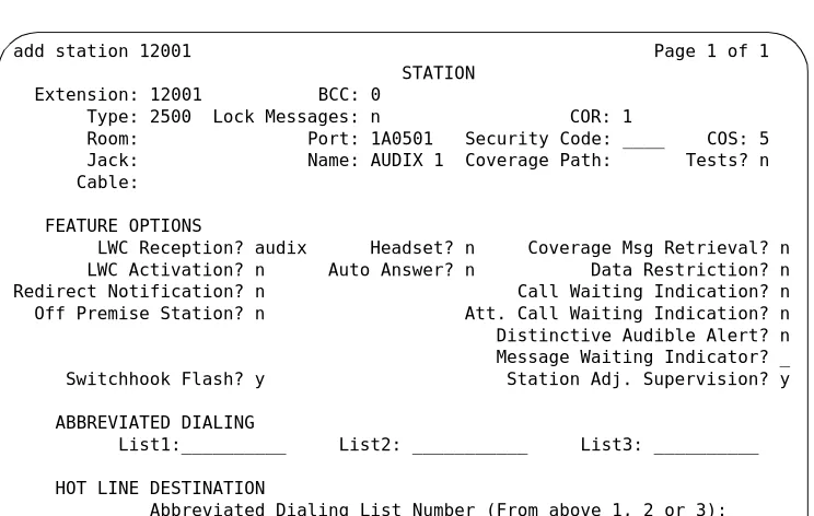
Administer the First Voice Port
The Intuity voice ports interact with the switch as 2500 analog stations. Refer to
Worksheet A: Voice Port Station Information, for the information required to administer the ports.
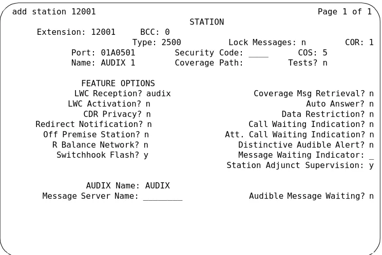
1. Enter add station < voice port extension> at the command prompt on the SAT. After you enter the command, you see the Station screen as shown in Figure 3-1..
The extension number must be the same length as the Intuity system subscriber extension numbers. Extension numbers cannot start with 0. You also can use the ad d station next command if you are adding stations sequentially.
Figure 3-1. Example G1 2500 Station Screen
2. Use Table 3-1 to enter the correct values in each of the screen fields. add station 12001 Page 1 of 1 STATION
Extension: 12001 BCC: 0
Type: 2500 Lock Messages: n COR: 1
Room: Port: 1A0501 Security Code: ____ COS: 5 Jack: Name: AUDIX 1 Coverage Path: Tests? n Cable:
FEATURE OPTIONS
LWC Reception? audix Headset? n Coverage Msg Retrieval? n LWC Activation? n Auto Answer? n Data Restriction? n Redirect Notification? n Call Waiting Indication? n Off Premise Station? n Att. Call Waiting Indication? n Distinctive Audible Alert? n Message Waiting Indicator? _ Switchhook Flash? y Station Adj. Supervision? y
ABBREVIATED DIALING
List1:__________ List2: ___________ List3: __________
HOT LINE DESTINATION
Issue 4 December 1995 3-5
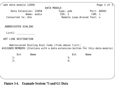
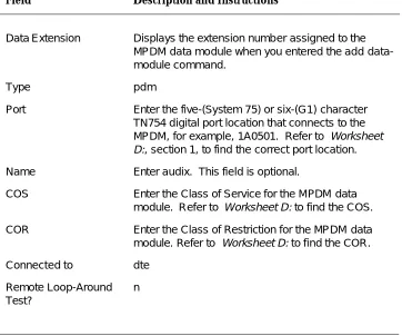
Table 3-1. System 75 and G1 Station Screen Entries Field Description and Instructions
Extension A valid extension number (3 to 5 digits) that agrees with the dial plan. Each voice port needs a unique extension number. Refer to Worksheet B: Voice Port Extensions and Names in Chapter 2 for a list of valid extensions to enter.
Type 2500
Lock Messages n
COR Class of Restriction: Enter a COR for the voice port that reflects the desired restriction. The COR provides security for the voice ports. Use the COR you configured in the "Create a Unique COR" section of this chapter. Worksheet A: Voice Port Station Information also contains the