Volume 2008, Article ID 385827,10pages doi:10.1155/2008/385827
Research Article
Hardware Implementation of a Spline-Based Genetic
Algorithm for Embedded Stereo Vision Sensor Providing
Real-Time Visual Guidance to the Visually Impaired
Dah-Jye Lee, Jonathan D. Anderson, and James K. Archibald
Electrical and Computer Engineering Department, Brigham Young University, Provo, UT 84602, USA
Correspondence should be addressed to Dah-Jye Lee,[email protected]
Received 30 November 2007; Accepted 25 February 2008
Recommended by P.-C. Chung
Many image and signal processing techniques have been applied to medical and health care applications in recent years. In this pa-per, we present a robust signal processing approach that can be used to solve the correspondence problem for an embedded stereo vision sensor to provide real-time visual guidance to the visually impaired. This approach is based on our new one-dimensional (1D) spline-based genetic algorithm to match signals. The algorithm processes image data lines as 1D signals to generate a dense disparity map, from which 3D information can be extracted. With recent advances in electronics technology, this 1D signal match-ing technique can be implemented and executed in parallel in hardware such as field-programmable gate arrays (FPGAs) to provide real-time feedback about the environment to the user. In order to complement (not replace) traditional aids for the visually im-paired such as canes and Seeing Eyes dogs, vision systems that provide guidance to the visually imim-paired must be affordable, easy to use, compact, and free from attributes that are awkward or embarrassing to the user. “Seeing Eye Glasses,” an embedded stereo vision system utilizing our new algorithm, meets all these requirements.
Copyright © 2008 Dah-Jye Lee et al. This is an open access article distributed under the Creative Commons Attribution License, which permits unrestricted use, distribution, and reproduction in any medium, provided the original work is properly cited.
1. INTRODUCTION
Traditionally, the visually impaired have used canes and/or Seeing Eye dogs to help them move about. In the appropriate settings, both of these approaches work well but both have limitations. Canes, for instance, provide information only at the lower leg level as they sweep back and forth. A visually impaired person using a cane is vulnerable to obstacles that are not at ground level, such as tree branches or low ceilings in stairwells. Guide dogs can be trained to help in these sit-uations, but communication between the dog and the user is limited to an indication that they are approaching an ob-stacle, often accompanied by a directional change to avoid it. If the visually impaired were to have accurate informa-tion about the environment, they could more safely navigate through it.
Available assistive technologies range from canes with embedded GPS systems to PDAs with Braille-based email, word processing, and music players, and so forth. Recent technological advances have made possible additional aids
for the visually impaired. In particular, vision systems are be-ing developed which allow the visually impaired to receive “visual” information through other senses by converting 3D information about the environment into alternate represen-tations, such as audio signals or electrical stimulation. For example, the tongue- display system uses voltage stimulation and a special mouthpiece to send visual information to the tongue of a user [1]. The vOICe vision technology group aims to provide similar feedback to the user through the use of sound [2]. By utilizing a pair of cameras and a laptop PC, the vOICe vision system provides audio information about the environment around the user. Kulyukin et al. developed an intelligent robot called “robotic guide dog” to comple-ment the performance of a guide dog in environcomple-ments that are not familiar to the dog or its handler [3]. Peli et al. de-scribe an embedded system that aids those not fully visually impaired to recognize faces [4].
player. Moreover, it should not cause discomfort or diminish the user’s ability to hear. For the visually impaired, hearing is the most important sensing ability, so the operation of a supplemental guidance system must not block hearing. Ap-pearance and cosmetic appeal are also important factors. As noted in [5], visually impaired people would be reluctant to use anything in public that makes them appear obviously dif-ferent from others or that could cause embarrassment. The existing systems and devices mentioned above [1–4] fail to meet these requirements.
Stereo vision is an important technique used to obtain depth information of objects in a 3D scene from two or more images taken from different view points [6]. To determine distance to objects, a stereo vision system must solve two im-portant problems: thecorrespondence problemand3D recon-struction. A solution to the latter is relatively straightforward if the geometry is known or the calibration of the two cam-eras is done properly. For a visual guiding system, highly ac-curate 3D scene reconstruction is not necessary. To meet the operational requirements of such a system, it is sufficient to produce—in real time—reasonable estimates of the location of potential obstacles and their distance from the user.
The major challenge in 3D information extraction is the correspondence problem, or determining which pixel or fea-ture in one view corresponds to which pixel or feafea-ture in the other view. Once this information is found, depth informa-tion can be inferred. Scharstein and Szeliski provide an ex-haustive analysis and comparison of the best stereo vision algorithms [7]. Most of these stereo vision algorithms are poorly suited for implementation in hardware, an important concern in meeting the cost, size, power consumption, and real-time requirements of our application.
Because stereo vision is an ill-posed problem, constraints associated with added assumptions are typically enforced to obtain satisfactory results. For example, similarities between images taken from two different viewpoints are strength-ened by controlling the lighting or restricting the length of the baseline between the cameras. Given properly calibrated cameras, the correspondence problem can be reduced to the 1D problem of matching pixels or features in corresponding scan lines. By processing 1D signals from the image data, a detailed disparity map of differences between the two views can be generated, allowing the distance to objects in the scene to be computed.
In this paper, we present a robust 1D signal matching method that employs spline representations and a genetic al-gorithm to obtain a dense disparity map. By imposing im-plicit smoothness constraints, matching parameters can be solved in terms of their spline representations by minimiz-ing a certain cost function. A genetic algorithm that is able to eliminate local extremities is then used to perform the optimized matching. Unlike most genetic algorithm-based
detection problems. We demonstrate the validity of our algo-rithm by presenting reconstruction results from four distinct scenarios.
Furthermore, we describe a new visual guiding device called “Seeing Eye Glasses” that meets the requirements we have identified and that utilizes our signal matching algo-rithm. The device is made possible by advances in technol-ogy that allow embedded systems to become both smaller and faster. Two compact color CMOS imagers are used as the input devices, and a custom-designed FPGA-based board is used as the visual data processing engine. The system uses a new stereo vision algorithm to extract 3D information from the environment in real time. From that information, the sys-tem detects potential obstacles and computes the approxi-mate distance to these obstacles and the time to impact. The Seeing Eye Glasses use miniature vibrators mounted in the frame near the ears to warn the user about imminent colli-sions. By changing the vibration frequency and controlling the vibrating actuator on each side separately, both direction and distance information can be conveyed.
The rest of this paper is organized as follows. Details about the algorithm and the processing flowchart are pre-sented in Section 2. Section 3 discusses the hardware ar-chitecture of our embedded system as well as the hard-ware implementation of our spline-based genetic algorithm. Section 4shows the simulation results of the algorithm and discusses the features of the proposed system. Finally, con-clusions and future work are discussed inSection 5.
2. SIGNAL MATCHING ALGORITHM
A general approach to solve the correspondence problem can be formulated as follows. First, consider thedisparity field de-fined by the distance a pixel in one image must be shifted to match the position of the corresponding pixel in the second image. More precisely, the disparity field,d(x), is defined for each pixelxby the following relationship:
Il(x+d(x))=Ir(x), (1)
whereIlandIrare intensity profiles from the left and right
view points, respectively. Once a reasonable estimate of the disparity field is known, 3D reconstruction is easily com-puted.
The most common method used to obtain optimal matching results is to minimize the error between the left im-age (shifted by the calculated disparitiesd(x)) and the right image:
x
Figure1: Control grid not aligned with the pixel grid.
However, due to the ill-posed nature of stereo vision, added constraints should be considered together with (2). These are explained inSection 2.3.
2.1. Spline representation for disparity fields
The disparity smoothness constraint specifies that the dis-parity changes slowly between any two points located near each other. This constraint can be enforced implicitly by us-ing splines to represent the disparity field. In other words, the disparity field can be expressed as 1D splines controlled by a smaller number of displacement estimates lying on a coarser spline control grid [10].
Figure 1shows a small set of pixel grid and control grid points. The small circles represent the control points for spline representations, and the vertical and horizontal lines form the pixel grid. Every image line has one set of control points that can be used to represent the disparity field. In this example, the spline control points are placed directly be-tween two adjacent pixels and located three pixels apart in each scan line.
Depending on the basis function used, different spline representations such as block, linear, orB-Spline can be de-rived.Figure 2shows the basis functions of a linear spline. The small circles represent the control points that can be used to calculate the disparity fieldd(x).The basis functions are implemented as
B(x)=
1−x x∈[0, 1],
1 +x x∈[−1, 0]. (3)
In our implementation, basis functions are shifted versions of each other as shown inFigure 2. In other words, they share the following forms:
Bi(x)=B(x−xi). (4)
The linear spline is selected because it is easy to imple-ment (relative to methods requiring more complex compu-tations), it can be processed quickly, and it provides satisfac-tory accuracy for applications such as obstacle avoidance and distance estimation.Figure 1shows that the control points need not fall exactly on pixel positions. In order to sim-plify hardware implementation and speed up the computa-tion process, we impose the condicomputa-tion that the spline control points are subsamples of the pixel grid [10], that is, they are
Figure2: Linear spline basis functions.
aligned with the pixel grid and can be expressed as
xi=mxi, (5)
wheremis the subsampling ratio, andxirepresents the pixel
grid. In this paper, we selectmto be 20 pixels, which gives a total of 32 control points (i=0, 1, 2,. . ., 31) for each line in a 640×480 image . The disparity field can then be calculated as
d(x)=
i
diBi(x), (6)
where eachBi(x) is a basis function with finite support.
2.2. Genetic algorithm
The genetic algorithm (GA) is an optimization tool, using stochastic global searching to mimic the metaphor of natural biological evolution. The technique is often used in comput-ing to find exact or approximate solutions to optimization and search problems. Compared to traditional search meth-ods, the four most obvious differences of GAs are the follow-ing [11].
(1) GAs search in parallel.
(2) GAs do not require the calculation of derivative infor-mation or other auxiliary knowledge.
(3) GAs use probabilistic rather than deterministic transi-tion rules.
(4) GAs work on an encoding of the parameter set rather than the parameter set itself.
ages). Because of the built-in smoothness constraint, the ap-proach is able to give satisfactory results, as will be shown in Section 4. The algorithm integrates the spline representation in every generation, takes every position available in the im-age into account, and produces a more detailed disparity map than other approaches. In this paper, we assume the intensity profile pair shares enough similarity for matching, which is the prerequisite for stereo vision.
Our goal is to minimize (2) to solve for the disparity field. However, due to the noise present in acquired images, taking (2) as the only term in the cost function is far from realistic. For real applications, the following constraints should also be enforced to reduce the searching space [13].
(1) Epipolar constraint: the corresponding points can lie only on the epipolar line in the second image.
(2) Uniqueness constraint: each pixel in one image corre-sponds to at most one pixel in the other image; in the cases of self-occlusion, no pixel may match.
(3) Ordering constraint: for surfaces of similar depth, cresponding feature points typically lie in the same or-der on the epipolar line.
(4) Photometric compatibility constraint: the intensities of the same point in the two images likely only differ by a small amount.
(5) Geometric similarity constraint: geometric character-istics of features such as line length or orientation do not differ greatly between images.
(6) Disparity smoothness constraint: the disparity changes slowly almost everywhere in the image between two points that are near each other.
(7) Figural disparity constraint: if a point lies on an edge element in one image, the corresponding point must also lie on an edge in the other image.
(8) Feature compatibility constraint: points can match only if they have the same physical origin, such as a dis-continuity on an object’s surface or being in the border of a shadow cast by another object.
(9) Disparity limit constraint: the disparity cannot exceed some fixed limit.
Constraint 1 is considered automatically, because we are dealing with the canonical camera configuration, in which case the epipolar line coincides with the scan line. Con-straints 2 and 3 can be integrated into the cost function by adding two terms shown in (7). Constraint 4 is the funda-mental of matching, which corresponds to the idea of min-imizing (2). Constraints 5, 7, and 8 can be used to check the validity of the result. Constraint 6 is taken care of by the spline representation. And finally, Constraint 9 is considered when we create the chromosomes for each generation. The
+w2· x
Ox+w3· y
(Cy(Y)−K(Cy(Y))).
(7)
In (7),iis the index of the control points, andxis the pixel position in the left image which has a possible match.Oxis
the ordering constraint indicator:Ox=1 if the ordering
con-straint is violated, otherwiseOx =0. Yis a vector of
posi-tion and each element of it is expressed as
Y(j)=x+d(x)=x+
i ∧
diBi(x). (8)
Meanwhile, the dummy variable for the summation y satis-fies
y∈N, y∈[min(Y), max(Y)]. (9)
Cy(Y) is a counting function. It takes a vectorY as an
input and returns the number of the elements inY with a value equal toy. K(x) is an indicator function, defined by
K(x)=
1 x≥1,
0 x=0. (10)
Finally,wi(i=1, 2, 3) are, respectively, the weights for
inten-sity error, the ordering constraint, and the uniqueness con-straint. It is possible to weight the intensity error from vari-ous parts of the intensity profile differently to get an even bet-ter match within certain local areas. For example, the error can be weighted more when the intensity is at a local maxi-mum or minimaxi-mum position by adding more terms to the cost function.
3. IMPLEMENTATION
3.1. Processing flowchart
Figure 3shows the data flow of the implementation of our genetic algorithm, which begins by creating 10 randomly generated sets of possible solutions calledcitizens. As men-tioned previously, the subsampling ratio for our spline con-trol points (themvalue in (5)) is set to 20, which gives 32 control points. Each citizen contains initial estimates of so-lutions to the 32divalues in (6). For each 1D image line pair
Line profile
pair At most
100 iterations
Create 10 citizens
Fitness function Record citizen
status Bad
Reach iteration limit or obtain optimal solution
% %
Do crossover
?
Crossover Yes
No Do
mutation ?
Yes Mutate
No
Return best solution
Create & insert new
citizen
Figure3: Dataflow of genetic algorithms.
or the insertion process [11] depending on specified proba-bilities (corresponding to the % signs shown inFigure 3). In our current implementation, both probability values were set to 50%, meaning that there is a 50% chance that a bad citizen will undergo crossover or mutation. A random number gen-erator generates a number between 1 and 100; if the number is less than the desired probability value then the citizen un-dergoes crossover or mutation. If neither crossover nor mu-tation is carried out, then a new citizen is generated to replace the bad citizen. This process is called insertion. The whole process of checking fitness and rearranging or inserting new citizens (solutions) is repeated for a fixed number of itera-tion, currently set to 100. Limiting the number of iterations and bounding the processing time are critical for real-time execution.
3.2. Hardware architecture
The system we have developed implements real-time 1D sig-nal matching for visual guidance on a custom FPGA board called Helios [14]. The FPGA is the sole computational sup-port for this embedded stereo vision sensor. It supsup-ports all processing associated with sensing, communication, and control. Our platform uses a Virtex-4 FX60 FPGA that in-cludes two 400 MHz PowerPC CPUs on-chip, in additional to configurable logic resources. Thus, our application has two forms of computational support: conventional proces-sors to run compiled C code, and custom hardware realized in the FPGA fabric.
Fundamental to the FPGA architecture is the notion of
aperipheral core(pcore) that contains a circuit module. As
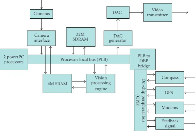
shown inFigure 4, the processor local bus (PLB) ties directly to the PowerPC on the FPGA chip. Because the PLB con-nects directly to the CPU, the response time is fastest for pcores placed directly on the PLB. The on-chip peripheral bus (OPB) can be connected to the PLB through a bridge, allowing communication to and from the PowerPC via the PLB. Since they cannot be accessed directly by the CPU, pcores connected via the OPB generally have longer response times. Thus, the two available buses tend to separate the com-ponents in the system into two categories, with those per-forming the most time critical operations connected to the PLB.Figure 4shows the architecture of the components
real-ized in the FPGA, including the pcores and the physical com-ponents themselves.
This hardware architecture includes a camera inter-face pcore that connects to two CMOS imagers, 32 MB of SDRAM for image storage, 4 MB of SRAM for fast tempo-rary image storage during processing, a vision processing en-gine for running image processing algorithms, and a digital-to-analog converter pcore that converts image data to analog form for transmission to a remote base station for debugging. Besides the output devices that provide feedback to the user, other peripheral devices such as a compass, a GPS receiver, and a modem can be connected to the OPB to expand the capabilities and functionality of the guidance system.
3.3. Hardware implementation
The hardware providing computational support for our guidance system consists of three major components: an im-age smoother, a collection of random number generators, and a datapath realizing the spline-based genetic algorithm. Each of these components is discussed in detail below.
Figure 5shows a block diagram of the image smoother that reduces the negative impact of noise in the image. This component is implemented as part of the camera interface pcore so that incoming image pixels are smoothed inline in real-time at camera frame rate. As can be seen, the smoother computes the average of each set of five adjacent pixels. This is done in multiple pipelined stages, each adding a single cy-cle of latency. In the first cycy-cle, two separate additions are performed, one with three operands and one with two. On the next cycle, the two partial sums are added, and then the division by 5 takes place. This latter operation is completed in a single cycle using a lookup table (LUT). As a result of this implementation, smoothed pixel data is available just a few cycles after the original pixel was obtained from the camera.
2 powerPC processors
4M SRAM
Processor local bus (PLB)
Vision processing
engine
PLB to OBP bridge
Compass GPS Modems Feedback
signal
On-c
hip
p
er
ipher
al
b
us
(OPB)
Figure4: FPGA hardware architecture.
Pixel
Reg5 Reg4 Reg3 Reg2 Reg1
+ + +
Division LUT Smoothed pixel
Figure5: Hardware implementation of an inline average filter.
In LdRnd
Random number FIFO
Signal
÷2.56 LUT
3
÷25.6 LUT
Use Rnd256 Rnd256 Rnd256
Use Rnd100 Rnd100 Rnd100
Use Rnd32 Rnd32 Rnd32
Use Rnd10 Rnd10 Rnd10
Figure6: Hardware implementation of random number genera-tors.
uses the original random byte stored in the random number FIFO to generate its output.
Rnd256 uses the number stored in the FIFO without modification. These values are interpreted as signed integers (−128 to 127) for the creation of initial genes, and inter-preted as unsigned integers (0 to 255) for the mutation oper-ation. Rnd100 uses a LUT to divide the original value by 2.56 to generate random numbers from 0 to 99. As discussed in
Section 3.1, these values are used to determine when to per-form crossover or mutation. The value in Rnd32 is obtained by shifting the original value from the FIFO right by 3 bits, generating a number from 0 to 31. These values are used to determine the starting gene (of the 32 in each citizen) for crossover operations. Rnd10 uses a LUT to divide the origi-nal value by 25.6. The resulting values (from 0 to 9) are used to randomly select one of the 10 citizens.
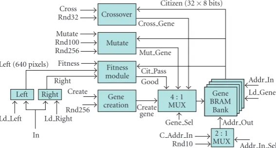
The datapath for the genetic algorithm is shown in Figure 7. The blocks labeled “Left” and “Right” correspond to block RAMs (BRAMs) that store the entirety of scan lines from the left and right images, respectively. The contents of these units are fed into the fitness module, which performs the calculation of (7). The module requires eleven cycles to determine whether a particular citizen is “good” or not, and this information is evaluated by logic controlling the data-path. If evaluated as “good,” the citizen is passed into the gene BRAM bank for storage. Otherwise, crossover, muta-tion, or insertion operations will be carried out depending on randomly generated probability values as discussed in Section 3.1.
The create gene module creates new citizens. For each re-quest, a random value is obtained from Rnd256 (interpreted as an integer ranging from−128 to 127) and passed into the gene BRAM bank to replace a bad citizen.
Left (640 pixels)
Left Right Right
Cross Rnd32 Mutate Rnd100 Rnd256
Fitness module
Create gene
C Addr In Rnd10 4 : 1 MUX Gene
creation
Gene BRAM
Bank 2 : 1 MUX Ld Left
In
Ld Right Fitness
Create Rnd256
Crossover
Mutate
Cross Gene
Mut Gene Cit Pass Good
Citizen (32×8 bits)
Gene Sel
Addr In Ld Gene
Addr Out Addr In Sel
Figure7: Hardware implementation of genetic algorithm.
The gene BRAM bank uses four BRAMs to encode the 32 genes. Each BRAM has a maximum size of 72 bits, enough to encode 8 8-bit values. Each BRAM operates in parallel but is accessed with the same address bits. This allows us to access and use the full 32 genes for a given citizen in parallel. The 32 genes also represent 32 control points, each of which is associated with 20 (subsampling ratiom) pixels. This means we need just 20 pixels of information at a time from each scan line when checking a citizen’s fitness.
All modules are designed to operate in a pipelined fash-ion, meaning that each can begin a new computation before its previous operations have completed. Moreover, by tim-ing control signals such that modules do not interfere with each other’s operations, multiple citizens can be processed in parallel, further increasing performance. The parallel and pipelined operation of the genetic algorithm module requires a dedicated control unit (not shown) to generate control sig-nals in the appropriate sequence and with the appropriate timing. The control unit for the genetic algorithm datapath is designed as a One-Hot encoded state machine with multiple paths through the state diagram, one for each major opera-tion. At initialization, the control unit creates 10 new random genes for testing. It is also fed the probability of mutation and crossover, ensuring that the correct number of crossovers and mutations takes place.
4. RESULTS
4.1. Embedded hardware components
Similar to the vOICe system, our embedded guidance sys-tem utilizes standard eyeglass frames to house the cameras. Unlike the vOICe system, however, our system utilizes field-programmable gate arrays to implement the hardware and software, reducing its overall size. In particular, our proto-type system uses the Helios board (shown in Figure 8(a)) developed at Brigham Young University [15]. The board is based on a powerful Xilinx Virtex-4 FPGA chip that includes two 400 MHz PowerPC processors, allowing for both custom hardware and software. By carefully utilizing the strengths of both hardware and software, the complete system can run in real time. Our Seeing Eye Glasses contain two CMOS
cam-eras (one shown inFigure 8(b)) that feed image data to the camera interface pcore on the FPGA. The actual connection to the camera is made through a daughter board (shown in Figure 8(c)) that connects to Helios via a 120-pin header. The FPGA performs our spline-based GA stereo vision algorithm, interprets (in software running on the on-chip CPUs) the re-sulting disparity map, and provides the location and time-to-impact of the obstacles to the user through a set of microvi-brators.
4.2. Simulation results
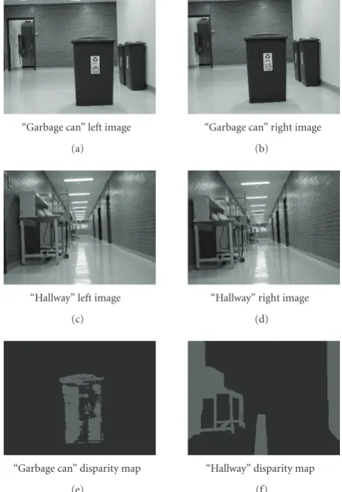
Our spline-based GA stereo vision algorithm was tested using both indoor and outdoor scenes.Figure 9shows a hallway containing a garbage can in the area of normal traffic flow. This scenario represents commonly occurring situations in which the assistive guidance system should help, so it consti-tutes a good test of the algorithm’s ability to determine the presence of obstacles. In the figure, dark portions of the dis-parity map are considered background, and gray portions are considered as the obstacle or foreground. As can be seen, the algorithm spotted the garbage can; the system could make use of this information to alert the visually impaired user of the approximate distance and direction to the obstacle.
Key to this approach is the assumption that rough esti-mates of distances to obstacles are sufficient for assisted nav-igation, so full and precise reconstruction of the complete 3D scene is not necessary. To obtain the results shown in Figure 9, results from multiple image frames were used to calculate the time-to-impact for the observed obstacle. An automated threshold was applied that isolated all the pixels in the disparity map with a disparity greater than or equal to the maximum disparity found minus an automated thresh-old value (e.g., the top 20% of disparity values). Erosion and dilation morphological operations were then used to filter image noise using a simple 3×3 kernel.
(a) (b) (c)
Figure8: Hardware components: (a) Helios FPGA board, (b) CMOS imager, and (c) AVT daughter board.
“Garbage can” left image (a)
“Garbage can” right image (b)
“Hallway” left image (c)
“Hallway” right image (d)
“Garbage can” disparity map (e)
“Hallway” disparity map (f)
Figure9: Indoor scenes: “garbage can” and “hallway”.
and the cameras were not perfectly calibrated in the canon-ical configuration (with the epipolar line parallel to image scan lines). The cameras are tilted slightly with respect to each other. Despite these challenges, the disparity map is ac-curate enough for the system to determine the location of (and hence distance to) the obstacle. No image rectification was necessary and no special compensation was added for the variations in illumination.
Figure 10shows the image pairs and disparity maps of two outdoor scenes. Both show promising results that are ad-equate for the system to warn the user about obstacles and
the distance to them. Hardware simulations indicate that our current FPGA-based design is able to process 640×480 im-ages at 9 to 11 frames per second, a sufficient rate to direct a user at the normal walking speed of 4.0 feet (1.2 meters) per second, or to provide update information approximately ev-ery 5 inches (12 cm). Processing speed varies with the num-ber of iterations required to reach an acceptable solution.
“Truck” left image (a)
“Truck” right image (b)
“Planter” left image (c)
“Planter” right image (d)
“Truck” disparity map (e)
“Planter” disparity map (f)
Figure10: Outdoor scenes: “truck” and “planter”.
close to the user. However, given a known camera height (or the height of the user), these areas can be determined to be directly in front of the user and at the same level as the ground the user walks on. Although the glare areas shown in both scenes seem to be at the same location, they have dif-ferent distance values that are not reflected in the binarized disparity maps. Objects appearing near the bottom of the image and at a distance equal to the height of the user can be removed. The guiding device can then ignore them and not send out a warning signal to the user. In the figure, the “planter” is located at the bottom of the image but “further” from the cameras than the known distance to the ground. Hence, the planter would be correctly identified as an obsta-cle. In the case that these areas are near the bottom of the image and have distances greater then the user’s height, then they will be interpreted as a drop-off(e.g., curb, pothole, de-scending staircase) and an appropriate warning signal would be sent.
4.3. Anticipated embedded system
The disparity information found by the algorithm leads di-rectly to reasonable estimates of distances to potential ob-stacles in the user’s surroundings, and then these estimates
trigger warnings to the user. Because the system operates in real time, the warnings come quickly and reliably as the user moves through the environment. Figure 11 illustrates the complete Seeing Eye Glasses system. At the user’s dis-cretion, the system provides information in the form of au-dio feedback in conventional headphones or vibrations pro-duced by microvibrators mounted on the ends of the frame near the ears. The latter feedback system warns the user by gently tapping on the skin. Time-to-impact is indicated by varying the tapping frequency, and the direction to the obsta-cle is indicated by differences in the magnitude or intensity of the tapping on one side relative to the other.
Figure11: Anticipated embedded stereo vision system.
Seeing Eye Glasses system meets all requirements mentioned inSection 1, including the cosmetic appeal.
This system supplements other assistive tools such as See-ing Eye dogs and canes. Because the SeeSee-ing Eye Glasses are worn just like normal sunglasses, the user’s hands are free to hold a cane or a dog’s harness.
The system can also be augmented with additional func-tionality without modifying the existing hardware. For ex-ample, using the visual cues from a sequence of image frames, the system can calculate not only the time-to-impact for obstacles, but also the tilting of the head by the user. This could, for example, be used to warn a user with an impaired sense of balance of an impending fall. By being both unob-trusive and simple to use, the embedded system can provide visual guidance to the visually impaired.
5. CONCLUSION
This paper has presented an embedded stereo vision system that can be used to assist the visually impaired. Our system design takes advantage of technologies we developed for mil-itary applications—real-time on-board vision processing for obstacle detection and avoidance on very small unmanned air vehicles—and applies them to an important application in health care.
Our approach uses splines and a genetic algorithm to per-form stereo vision correlation in order to generate dense dis-parity maps. These disdis-parity maps, in turn, provide rough distance and orientation estimates to the user, assisting in the navigation through an unknown environment. Using dispar-ity maps from multiple image frames, the time to impact an obstacle and the tilt of head can also be calculated.
Our results showed that our algorithm provides adequate results for the purpose of guiding a human user. The algo-rithm does not require complicated image rectification, and it is robust in the face of imperfect stereo system configura-tion, improperly calibrated cameras, and variations in illumi-nation. A simulation of a preliminary hardware design shows that the system is able to update the 3D information at 9 to 11 frames per second. We anticipate that design optimiza-tions will result in higher frame-rates sustained in real-time operation.
Future work includes completing the hardware and soft-ware design for the FPGA as well as building the embedded
This work was supported in part by David and Deborah Hu-ber.
REFERENCES
[1] University of Wisconson-Madison, Tongue Vision Unit, http://kaz.med.wisc.edu/TDU.htm.
[2] “Vision Technology for the Totally Blind,” vOICe technology, http://www.seeingwithsound.com.
[3] V. Kulyukin, C. Gharpure, J. Nicholson, and G. Osborne, “Robot-assisted wayfinding for the visually impaired in struc-tured indoor environments,” Autonomous Robots, vol. 21, no. 1, pp. 29–41, 2006.
[4] E. Peli, R. B. Goldstein, G. M. Young, C. L. Trempe, and S. M. Buzney, “Image enhancement for the visually impaired: simu-lations and experimental results,”Investigative Ophthalmology and Visual Science, vol. 32, no. 8, pp. 2337–2350, 1991. [5] S. Upson, “Tongue vision: a fuzzy outlook for an unpalatable
technology,”IEEE Spectrum, vol. 44, no. 1, pp. 44–45, 2007. [6] E. Trucco and A. Verri,Introductory Techniques for 3-D
Com-puter Vision, Prentice Hall, Upper Saddle River, NJ, USA, 1998. [7] D. Scharstein and R. Szeliski, “A taxonomy and evaluation of dense two-frame stereo correspondence algorithms,” Interna-tional Journal of Computer Vision, vol. 47, no. 1–3, pp. 7–42, 2002.
[8] Y. Ruichek, H. Issa, and J.-G. Postaire, “Genetic approach for obstacle detection using linear stereo vision,” inProceedings of the IEEE Intelligent Vehicles Symposium (IV ’00), pp. 261–266, Dearbon, Mich, USA, October 2000.
[9] S. Woo and A. Dipanda, “Matching lines and points in an ac-tive stereo vision system using genetic algorithms,” in Proceed-ings of IEEE International Conference on Image Processing (ICIP ’00), vol. 3, pp. 332–335, Vancouver, Canada, September 2000. [10] R. Szeliski and J. Coughlan, “Hierarchical spline-based image registration,” inProceedings of IEEE Computer Society Confer-ence on Computer Vision and Pattern Recognition (CVPR ’94), pp. 194–201, Seattle, Wash, USA, June 1994.
[11] University of Sheffield, “The MATLAB Genetic Algorithm Toolbox v1.2 User’s Guide,” http://www.shef.ac.uk/acse/re-search/ecrg/gat.html.
[12] P. Chalermwat and T. El-Ghazawi, “Multi-resolution image registration using genetics,” in Proceedings of IEEE Interna-tional Conference on Image Processing (ICIP ’99), vol. 2, pp. 452–456, Kobe, Japan, October 1999.
[13] M. Sonka, V. Hlavac, and R. Boyle, Image Processing, Anal-ysis, and Machine Vision, Brooks/Cole, St. Paul, Minn, USA, 2nd edition, 1999.
[14] W. S. Fife and J. K. Archibald, “Reconfigurable on-board vi-sion processing for small autonomous vehicles,” EURASIP Journal of Embedded Systems, vol. 2007, Article ID 80141, 14 pages, 2007.