National Conference “CONVERGENCE 2016”, 06
-07
April 2016
A Case Study of Reduction of Single-Phase
Transformer Magnetizing Inrush Current
Kunal Wakode1,Shaikh Sabir2, Nishant Adhau3, Abuzar Khan4, Prof. P. B. Shelke5 Department of Electrical Engineering1,2,3,4,5, Research Scholar1,2,3,4, Associate lecture5
Email:[email protected], [email protected]
Abstract-At the time of transformer energization, a high current will be drawn by the transformer. The mentioned current is called transient inrush current and it may rise to ten times the nominal full load current of transformer during operation. Energization transients can produce mechanical stress to the transformer, and it often affects the power system quality and may disrupt the operation of sensitive electrical loads such as computers and medical equipment connected to the system.
Reduction and the way to control of energization transients currents have become important concerns to the power industry for engineers. This paper discusses the different techniques for reduction of inrush current in transformer.
Keywords- Controlled switching; sequential phase energization; prefluxing technique; virtual air-gap
technique; Super conductor technique.
1. INTRODUCTION
Transformer is considered as the most important apparatus as heart in electrical transmission and distribution system. When a transformer is first energized, a transient current many times larger than the rated transformer current can flow for a number of cycles. Inrush currents are of very high magnitude generated when transformer cores are driven into saturation during energization. The worst inrush current happens to flow when the primary winding is supplied at an instant of voltage zero crossing. These currents have undesirable effects such as reduced power quality on the system, loss of life to the transformer itself. To mitigate this magnetizing inrush current, few of the methods are discussed as controlled switching, sequential phase energization, virtual air gap technique, prefluxing technique, supercoductor.
2. DIFFERENT TECHNIQUES
2.1. Prefluxing Technique
This technique presented an inrush current reduction which sets the residual flux of a three-phase transformer to a large magnitude and specific polarity in a method known as pre-fluxing and then energizes the transformer at a specified system voltage angle based on the flux polarity. This strategy has advantages over some of the presently suggested reduction strategies, including removing the need for residual flux measurements during transformer de-energization[1].
To minimize the peak of inrush current in three phase two winding transformer and obtained it to the steady state value, also to remove the transient component of flux in the core, there are several
methods. In this paper, two different strategies of mitigation of inrush current in power transformer like Point on Wave technique and Prefluxing technique are modeled & compared. In Point on Wave, circuit breaker is closed according to flux polarity in core. In prefluxing, first set flux using prefluxing device and then close circuit breaker according to that flux polarity.
The prefluxing device that sets the flux of the transformer is simple in form and flexible to apply to any range of transformer sizes. In addition, the device can operate at low-voltage levels, such as the substation ac or dc supply, regardless of the voltage rating of the transformer. The results of energizing a prefluxed transformer were presented, including accounting for breaker deviation; all with inrush current levels below the transformers rating, proving the effectiveness of the reduction procedure. These greatly reduced inrush currents mean reduced stress and degradation of the transformer windings and reduced system effects, such as harmonic over voltages or sympathetic inrush in neighboring transformers. Many techniques had been suggested to obtain residual flux on the basis of the instant of transformer was previously turned off. But it is slightly tedious process. To make a user free from knowledge of residual flux the paper proposes a new technique to set the initial fluxes of transformer as per the desired values. This is called as prefluxing.
The innovation behind the prefluxing inrush current reduction strategy lies in the prefluxing device itself. The prefluxing device capacitor is charged to a user-specified voltage and then discharged into the transformer when closing the device switch. It is necessary for the prefluxing device to set the residual flux of a transformer as high as possible to minimize the inrush current, but also to do so efficiently.
National Conference “CONVERGENCE 2016”, 06
-07
April 2016
flux when the transformer is de-energized. The [image:2.612.120.276.152.282.2]second part of the process controls the CB to energize the transformer at either an angle of 210 for positive residual flux, or 330 for negative residual flux. These angles are chosen as part of an inrush current reduction strategy for three-phase transformers that enable the use of a three-pole CB[1].
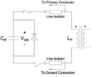
Fig. 1. Prefluxing device
The prefluxing device is shown in Fig.1 it consists of a capacitor, a diode, a fuse, and a switch. A charging circuit (not shown) establishes the initial voltage across the capacitor. The device is used when the transformer is isolated from the power system and connects across one of the transformer windings (the primary winding in the figure). Ideally, the highest voltage winding is used because of the reduced magnetizing current on this winding. Since the prefluxing device is only applied when the transformer is isolated and can operate at very low voltages, relatively inexpensive isolator switches can be used to connect the device to the transformer. The prefluxing device is sized to operate around the transformers magnetizing current levels, so the capacitor, diode, and fuse can be sized for a fraction of the transformer rated current.
2.2. Controlled Switching
The closing resistors have been used to reduce the magnitude of inrush currents. Controlled closing or controlling the point on power frequency voltage wave where energisation occurs has also been employed to reduce these inrush currents. The power transformers are operated with peak core flux at the knee of transformer core’s saturation characteristics. The sinusoidal core flux is the integral of applied voltage. When the transformer is de-energised, a permanent magnetization of the core remains due to hysteresis of magnetic material. This residual flux is influenced by the transformer core material characteristics, core gap factor, winding capacitance and other capacitances connected to the transformer[4].
The core flux and therefore residual flux can be measured by integration of winding voltage. When the transformer is energised, the instantaneous magnitude of core flux at the instant of energisation is the
residual flux. The amount of offset of the sinusoidal flux generated by the applied voltage is dependent upon the point of voltage wave where transformer is energized. The peak core flux Φ can therefore reach a value of 2Φnormal + Φresidual.
For the most severe case, where energisation was at a voltage zero, the peak transient core flux is more than two times higher than peak normal core flux. The core has been driven into saturation. This asymmetrical saturation results in the typical inrush current transient characterized by a high harmonic content and a direct current component. Although the closing resistors have been employed to reduce these transients, the only way these transients can be eliminated is to prevent the core saturation. This can be accomplished by controlling the instant of energisation. Controlled switching of single phase transformers In case of Controlled closing of capacitors, optimal energization point is at the instant when the source voltage is equal to the trapped charge voltage on the capacitor. For the case of controlled closing of transformers, the “trapped charge” has a parallel in the residual flux. So the basic principle to eliminate the core flux asymmetry, the “induced” flux (integral of applied voltage) at the instant of energization must equal the residual flux. There is of course no induced flux before energization, but the source voltage has the prospect to create an induced flux. If the source voltage is considered as a virtual flux source, then an optimal instant to energize transformer is when the prospective flux is equal to the residual flux. It provides the basic strategy for controlled closing on single phase transformers[2].
In case of controlled switching in multiphase transformer with no residual flux, only transformers with single-phase cores and only grounded windings may be considered as three single phase transformers, but most transformers on power systems have interaction between the phases. In these other transformers, after one phase has been energised, the flux in the other cores or core legs is not a static residual flux, but a transient flux, in the following called “dynamic” core flux. Residual Flux: The residual core flux can assume values up to 85% of peak normal flux, although more typical magnitudes are in the range of 20 to 70%. In most three phase transformers, it is possible to use residual flux measurements and controlled closing to eliminate transformer inrush transients. The residual flux can assume values up to 85% of peak normal flux, although more typical magnitudes are in the range of 20 to 70%. The residual flux in the cores of three phase transformers must inherently sum to zero, and typically forms a pattern with near zero residual flux in one phase and plus & minus some finite values in the other two phases. To mitigate inrush current in transformers, three strategies are proposed for controlled energisation of multi-phase transformers.
National Conference “CONVERGENCE 2016”, 06
-07
April 2016
mechanical closing time from operation to operation.For a breaker designed for controlled closing, typical closing time deviations are less than ± 1 ms. In selection of closing instant, it is important to consider these timing deviations and to understand the influence they have when considered together with flux transients and prestrike. Timing deviations caused by very long periods between operations (idle time) can be a potential difficulty in some circuit breaker design. Reduction of over 90% from the worst case inrush currents can be achieved with a circuit breaker of normal closing time performance. This can be accomplished by measuring the residual flux in transformer core, and using that information with the appropriate breaker closing control strategy. The phenomenon of core flux reduction can greatly simplify closing strategies, allowing the delayed strategy to be very effective. The delayed strategy can also provide a reduction of inrush transients when switching transformers with more thanthree corelegs and no delta connected winding. However, complete elimination of inrush currents is not possible with this configuration[5].
2.3. Sequential Phase Energisation Technique
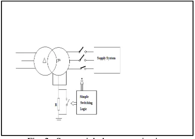
This is a simple and low cost method to reduce inrush currents caused by transformer energisation. The method uses a grounding resistor connected at a transformer neutral point. By energizing each phase of the transformer in sequence, the neutral resistor behaves as a series inserted resistor and thereby significantly reduces the energisation inrush current. This method is much less expensive, however, since there is only one resistor involved and the resistor carries only a small neutral current in steady-state[7].
[image:3.612.98.295.532.672.2]Inrush currents from transformer and reactor energisation have always been a concern in power industry. Over the past several decades, a few methods have been proposed to limit the inrush current. Representative examples are the synchronous closing of circuit breakers and pre-insertion of series resistors.
Fig. 2. Sequential phase energization In view of the fact that the inrush currents are always unbalanced among three phases, a neutral resistor could provide some damping to the currents. This is the basis of the proposed idea. The ideas are
further improved by introducing delayed energisation of each phase of the transformer. This improvement has made the proposed scheme almost as effective as the pre-insertion resistor scheme.
It is well known that inrush currents are highly unbalanced among three phases. If a transformer is Y grounded at the energisation side, its neutral current will also contain the inrush current. One may therefore speculate that if a resistor is inserted into transformer neutral, it may reduce the magnitude of the inrush current in a way similar to that of the series-inserted resistor. This consideration formed the basic idea of the proposed scheme[8].
Simultaneous closing of all three-phase breakers did not produce sufficient reduction on the inrush currents. However, if one closes each phase of the breaker in sequence with some delays between them, the neutral resistance could behave as a series resistor and improve the results. This simple improvement has proven to be very effective. In fact, the idea of sequential energisation of three-phase equipment can lead to a new class of techniques to reduce switching transients.
2.4. Super Conductor technique
Modern Power Systems are growing fast with more generators, transformers and large network in the systems. The installation, running and maintenance costs of the power system equipment are more. Whenever a fault occurs, there is a need for the protection of these systems. Power System Protection is a branch of electrical power engineering that deals with the protection of electrical power systems from faults through the isolation of faulted parts from the rest of the electrical network. Superconductors are one of the last great frontiers of scientific discovery. Here, in this Technique we discuss the use of Super Conductors as protective devices for Surge Current Protection. Superconductors conduct electricity offering zero resistance below certain temperatures.
2.4.1. Superconductive FCL
Superconductors offer a way to break through system design constraints by presenting impedance to the electrical system that varies depending on operating conditions. Superconducting fault-current limiters normally operate with low impedance and are "invisible" components in the electrical system. In the event of a fault, the limiter inserts impedance into the circuit and limits the fault current. With current limiters, the utility can provide a low-impedance, stiff system with a low fault-current level.
National Conference “CONVERGENCE 2016”, 06
-07
April 2016
(HTS) enables the development of economical [image:4.612.96.285.225.335.2]fault-current limiters. Superconducting fault-current limiters were first studied over twenty years ago. The earliest designs used low temperature superconductors (LTS), materials that lose all resistance at temperatures a few degrees above absolute zero. LTS materials are generally cooled with liquid helium, a substance both expensive and difficult to handle. These discoveries in 1986 of high temperature superconductors, which operate at higher temperatures and can be cooled by relatively inexpensive liquid nitrogen, renewed interest in superconducting fault-current limiters.
Fig. 3. Fault Current limiter
2.5. Virtual Air Gap Technique
This technique is based on the use of virtual air gap which equivalent thickness varies in function of controllable parameters adapted to the configuration of magnetic circuit and the associated control system. This study aims to modify the reluctance of a magnetic circuit using auxiliary windings called AGW (Air Gap Windings). The AGW current is either set to a specific value using an external source, or a current sensor, in the main magnetization winding of the magnetic circuit. Physically, the effects observed on the experimental system are very similar to those of devices with a real built-in-air-gap. The originality of the method is in the control of the air gap thickness by the AGW current. Using an AGW always requires a magnetic circuit which is magnetized through a main winding (primary of a transformer)[3].
2.5.1. Mechanical stability problem
Frames installed on the top and bottom yokes as well as in lateral columns in single-phase designs, are the most common and functional solution used to give mechanical support to windings and core. The set of core, windings and frames are put into a tank made of steel plates. Stiffeners are usually provided on all the sides and top cover to reduce stress and deflections under different types of loads. In fixed reactors, the physical result in magnetic fringing and mechanical vibrations. As the material possesses a very high modulus of elasticity, it is possible to obtain a lowest mechanical resonant frequency that is considerably
higher than the excitation frequency, i.e., double the system frequency. The danger of vibration damage resulting from resonance excitation therefore disappears. Magnetic fringing and mechanical vibrations disappear completely when the virtual air-gap concept is applied. This is one of advantages of this concept; however, the mechanical design challenge is now the relative position of all the fixing frames in order to support the complete internal structure
[image:4.612.323.506.359.485.2]The virtual air-gap principle consists in modifying the magnetization characteristic of a magnetic circuit by an additional unidirectional magnetic flux produced by a set of control or auxiliary windings fed by a direct current. This produces zones of controlled magnetic saturation level, called virtual air-gaps, whose effects are very similar to those of devices with real built-in air-gaps. The advantage of this method is that the equivalent length of the virtual air-gap can be controlled by the magnitude of the dc current applied to the auxiliary windings, achieving a controlled change in the magnetic core reluctance. This method offers the possibility of developing different solutions in practical applications such as reduction of the inrush current in transformers, voltage transformers without tap changer, and variable reactors.
Fig. 4. design concept of Virtual Air Gap Technique.
Fig. 5. Inductance Of VGR For Different Values Of Control Current
[image:4.612.320.513.507.653.2]National Conference “CONVERGENCE 2016”, 06
-07
April 2016
2. CONCLUSION
The phenomenon of current reduction can greatly simplify closing strategies, allowing the delayed strategy to be very effective. The delayed strategy provides a reduction of inrush transients when switching transformers with more than three core legs and no delta connected winding. However, complete elimination of inrush currents is not possible with theses configurations. In Sequential phase energization technique; there is an optimal neutral resistor value for the proposed scheme. This value is a compromised value between the need to suppress the inrush currents when the first two phases are energized and need to suppress the current when the third phase is energized. It is not essential to use an exact optimal value. Resistances around the optimal value are almost equally effective. With the proposed resistance value(s), the neutral resistor based scheme can lead to 80% to 90% reduction on inrush current. A small neutral resistor size of less than 10 times the transformer series saturation reactance can achieve 80 to 90% reduction in inrush current among three phases.
Acknowledgement
I avail this opportunity to express my deep sense of gratitude and whole hearted thanks to my guide and also our head of Electrical Engineering (Electronics & Power) Department Prof. P. B. Shelke, for giving His valuable guidance inspiration and affectionate encouragement to embark this paper. I also acknowledge my over whelming gratitude and immense respect to our principal,
Dr .P .M. Jawandhiya who inspired me a lot to
achieve the highest goal.
My thanks also goes to other staff members of, Electrical Engineering (Electronics & Power) Department my parents and my friends who are directly or indirectly involved in making the paper successful.
REFERENCES
[1] Pradeep J. Kotak, Prof. Alka Thakur. (November-2014): Comparative Analysis of Point on Wave Switching Technique & Prefluxing Technique to Mitigate In-rush Current in Three Phase Power Transformer, IJSER, Volume 5, Issue 11. [2] F. Fard Ali Asghar.; K. P. Basu.; (Nov. 2009):
Reduction of three-phase transformer
magnetizing inrush current by use of point on
wave switching, proceeding IEEE SCOReD
2009,
[3] J. Avila-Montes.; E. Melgoza (2000): Scaling the Virtual Air-gap Principle to High Voltage Large
Power Applications.
http://www.researchgate.net/publication/2366469 13
National Conference “CONVERGENCE 2016”, 06
-07
April 2016
using controlled switching and magnetic fluxshunts, International Journal of Energy and Power Engineering.
[5] Haresh S. Nankani , R. B. Kelkar, Review on Reduction of Magnetizing Inrush Current in Transformer,International Journal of Science and Research (IJSR) ISSN (Online): 2319-7064 Index Copernicus Value (2013): 6.14 | Impact Factor (2013): 4.438
[6] Enesi Asizehi Yahaya,Effect of Switching angle on Magnetizing flux and Inrush current of a Transformer, IOSR Journal of Electrical and Electronics Engineering (IOSR-JEEE) e-ISSN: 2278-1676,p-ISSN: 2320-3331, Volume 8, Issue 3 (Nov. - Dec. 2013), PP 20-22
[7] Yu Cui, Sami G. Abdulsalam, Shiuming Chen, Wilsun Xu,A Sequential Phase Energization Technique for Transformer Inrush Current Reduction,IEEE transactions on power delivery, vol. 20, no. 2, april 2005.
[8] Reena Moon , R.K.Dhatrak, A Study of Effect of Magnetizing Inrush Current on Different Ratings Of Transformers,IJAREEIEVol. 3, Issue 4, April 2014.