241
Design, Fabrication and Strength Analysis of
Connecting Rod to Improve the Life and Damage
Performance
Gangadhara Sudhakara, K Srinivasa Raob
a
M.Tech Student, bAssociate Professor, Department of Mechanical Engineering, Malla Reddy Engineering College, Secunderabad, Telangana, India.
Abstract: In a reciprocating piston engine, the connecting rod connects the piston to the crank or crankshaft. The IC engine vehicles require at least one connecting rod depending on the usage of no cylinders in engine. It
encounters high cyclic loads of order, 108 to 109 cycles, pitching from high compressive loads caused by combustion, to high tensile loads because of inertia. So, durability of the component is of vital importance. In prevailing automotive IC engines, the connecting rods are most usually made of steel for production engines, or of cast iron in applications such as motor scooters. The primary theme of this study is to explore and replace the existing connecting rod made of forged steel, so as to improve the performance and life of connectingrod.
This paper is to inquest the failure analysis of the connecting rod in the present day automotive engines. The materials such as Aluminium Oxide - Al2O3, Titanium Carbide TiC are considered in this case study. A connecting rod model is designed in CATIA V5 modelling software. The static analysis is carried out utilizing the finite element analysis codes. Design calculations and forces are calculated, analysis is carried out on the connecting rod for new material in ANSYS and then the results are compared and final material is picked out among them which gives the better performance. Next proceed for manufacturing the prototype of the connecting rod which is made using forging and direct machining. Experimental test are conducted on the prototype and the obtained experimental value are compared with the existing values.
Keywords: connecting rod; modelling; weight optimization; stress analysis, manufacturing prototype, experimental test.
1. INTRODUCTION:
The connecting rod is an intermediary member between the piston and the crankshaft. Its primal purpose is to transmit the push and pull from the piston pin to the crankpin and thus it converts the liner to and fro motion of the piston into the rotary motion of the crank. The I.C. engines use either diesel or petrol as their feed or propellant. In petrol engines or IC engines. The proper proportion of petrol and air is mixed in the carburettor and supplied to engine cylinder where it is ignited by a spark generated at the spark plug.
In the authentic diesel motor, just air is at first inhaled into the ignition chamber. The air is then highly combined with a pressure proportion normally in the scale of 15:1 and 22:1 accomplishing 4.0 MPa (40-bar) weight rambled from 0.8 to 1.4 MPa (8 to 14 bars) in the oil engine. This heavy weight heats up
the air to 550 °C (1,022 °F). At about the most significant purpose of the weight stroke, fuel is fed directly into the compacted air in the ignition chamber. This may be into a (linearly toroidal) void in the most prodigious purpose of a pre-chamber relying upon the arrangement of the engine. Because of the shoot affect in the barrel leads an increase in weights inside the chamber, in turn which causes a load on the chamber that consequently leads to the partner bar, which may provoke an explanation behind dissatisfaction of interfacing end.
2. LITERATURE REVIEW:
242
estimations. A parametric model of connecting pole
is demonstrated utilizing SOLID WORK
programming and to that model, examinations and result comparisons are done by utilizing ANSYS.
Dr.N.A.Wankhadel, SuchitaIngale(2017), Review on Design and Analysis of Connecting rod using variety of materials and calculation of Forces generated on the associated bar. Large loads due to the weight and ignition of fuel inside chamber follows up on cylinder and afterward on the interfacing bar, which brings about both the twisting and pivotal burdens. The present paper endeavors to plan and break down the interfacing pole utilized as a part of a diesel motor in setting of the parallel bowing powers acting along its length amid cycle of it. The horizontal twisting pressure is usually called as whipping pressure and this whipping pressure frames the base of assessment of execution of different materials that can be utilized for assembling of associating bar. The customary material utilized is steel which is designed utilizing CAD apparatus which is CATIA V5 and thusly broke down for twisting pressure following up on it in the field of limited component examination utilizing ANSYS workbench 14.5 and this method is taken after for various material which are High Strength Carbon, aluminum 6061 and aluminum 7075.
D.Gopinatha, Ch.V.Sushmab, al (2015), Plan and Optimization of Four Wheeler Connecting Rod Using Finite Element Analysis, The fundamental goal of research was to investigate weight lessening open doors for the generation of manufactured steel, aluminum and titanium interfacing poles. This has involved playing out a point by point stack examination. Subsequently, this investigation has managed two subjects, in the first place, static load pressure examination of the interfacing bar for three materials, and second, improvement for weight of
manufactured steel associating bar. In this
exploration, initially an suitable geometrical model was produced utilizing CATIA. At that point the model is foreign made to the HYPERMESH which is a limited component pre-processor that gives a immensely intelligent and visual scenario to break down the item plan execution and the Finite Element demonstration was created. The anxieties were found
in the present associating bar for the given stacking conditions by utilizing the Finite Element Analysis programming ANSYS 11.0. The topology
enhancement system is deployed to achieve the targets of streamlining which is to decrease the weight of the interfacing pole.
Dongkai Jia, Ke Wu, Shi Wu, Yuntong Jia, Chao Liang al. (2011), The Structural examination and Optimization of Diesel Engine Connecting Rod, This article presents a technique for the associating pole structural limited component investigation and optimization. Consolidating with 6120Q-1 show diesel motor associating bar, a model of interfacing pole system is worked by CATIA in the meantime. By stacking, squeeze dispersion on joining zones of associating pole, stretch conveyance and quality of interfacing bar are inferred to upgrade the plan of the interfacing bar. As indicated by the restricted part examination comes to fruition, by changing the security factors we get a statute acclimate to the 6120Q-1.
243 Isa MetinOzkara and Murat Baydog A, (2016),
Optimization of Thixoforging Parameters for C70S6 Steel Connecting Rods. A microalloyed steel, C70S6, with a solidifying break of 1390-1479 C, was thixo forged in the semisolid state in a close chomp the dust at temperatures in the ranging from
1400-1475 C to frame a 1/7 reduced model of a traveler vehicle interfacing pole. Bite the dust outline and an advanced thixo forging temperature wiped out the extreme glimmer and different issues amid producing. Strain tests from interfacing poles thixo fashioned at the ideal temperature of 1440 C shows almost a similar hardness, yield quality and extreme rigidity as the traditional hot manufactured examples. However, the pliability is diminished by 45% because of grain limit of ferrite organize shaped amid cooling from the thixo forging temperature. In this way, C70S6-review steel can be thixo forged at 1440 C to frame streak free interfacing bars. This conclusion was likewise approved utilizing FEA investigation.
Forces Acting on the Connecting Rod:
The various forces acting on the connecting rod are as follows:
1. Force on the piston caused by gas pressure and inertia of the reciprocating parts:
The force on the connecting rod is maximum when the crank and the connecting rod are complementary to each other (i.e. when θ = 90°). But at this position, the gas pressure drops considerably. Thus, for all practical condition, the maximum force on the piston due to pressure of gas (FL), is taken equal to the force in the connecting rod (FC), inertia effects are neglected.
2. Force due to inertia of the connecting rod or inertia bending forces:
The maximum bending moment alter as the square of speed. So, the bending stress caused by the elevated speeds will be vulnerable or risky. It may also be inscribed that the maximum bending stress and maximum axial force do not recur simultaneously. In an I.C. engine, the maximum gas load is developed close to the top dead centre whereas the maximum
bending stress is developed at the crank angle θ = 65° to 70° from top dead centre. Thus in general, connecting rod is designed by considering the maximum force due to gas pressure (FL) is equal to force in the connecting rod (FC), neglecting the effects of inertia due to piston and then verified for bending stress caused by inertia force (i.e. whipping stress).
Design of connecting rod:
The cross-section of the shank portion of connecting rod may be rectangular, tubular, circular, H-section or I-section. In general, low speed engines opt for circular section and high speed engines prefer I-section.
Thickness of the rib and web of the segment = t Width of the segment, B = 4 t
Profundity or stature of the area, H = 5t Territory of the cross area = 11t2 I xx/I yy = [419/12] x [12/131] = 3.2
Since the estimation of Ixx/Iyy lies in the scale of 3 and 3.5. Hence I-segment picked is very desirable.
Configurations of the Engine:
Suzuki 160cc Specifications Engine compose air cooled 4-stroke
Associating pole length = 117.2 mm Bore/Piston width = 57 mm
Stroke length = 58.6 mm
Radius of crank (r) = stroke length/2 = 58.6/2 = 29.3 Speed of the motor = 1800 r.p.m.
Most extreme gas weight = 15.5 MPa Greatest Power = 13.8 bhp @ 8500 rpm Most extreme Torque = 13.4 Nm @ 6000 rpm
Design Calculations for Connecting Rod:
Thickness of the rib or web of the segment = T = 3.2 mm
Width of section B = 4t = 4×3.2 = 12.8 mm Height of section H = 5t = 5×3.2 = 16 mm Area A = 11t2 =11×3.2×3.2 = 112.64 mm2
244
Tallness at the little end (cylinder end) H1 = 0.9H to 0.75H =12 mm
Stroke length (l) =117.2 mm Measurement of cylinder (D) =57 mm P=15.5 N/mm2
Radius of crank(r) =stroke length/2 = 58.6/2 = 29.3
Internal diameter of small end = 14.84 mm External diameter of small end = 20.94 mm Internal diameter of big end = 35.89 mm External diameter of big end = 47.72 mm
Modelling in Catia V5:
Modelling of connecting rod is done in Catia V5 based on the design calculations. The major and minor diameter, thickness, length of connecting pole are taken from the design calculations. Then model is produced in Part Design of Mechanical Design module in Catia. The planes in sketcher are selected carefully based on the which view it is to be drawn.
Final product:
Drafting:
Material Properties and Selection:
The materials including Aluminium Oxide - Al2O3, Titanium Carbide TiC are considered in this study. These materials are selected by comparing their properties with already existing material properties i.e., forged steel.
Material properties of Forged Steel:
Density 7.85e-006 kg mm-3
Thermal Conductivity 1.9e-002 W mm-1 C-1
Young's Modulus 2.1e+005 MPa
Poisson's Ratio 0.3
Bulk Modulus 1.75e+005 MPa
Shear Modulus8.0769e+005 MPa
Tensile Yield Strength 1900 MPa
Compressive Yield Strength 390 MPa
Material properties of Titanium Carbide TiC:
Density 4.93e-006 kg mm-3
Thermal Conductivity2.1e-002 W mm-1 C-1 Specific Heat 3.38e+007mJ kg-1 C-1
Young's Modulus 5.1e+005 MPa
Poisson's Ratio 0.191
Bulk Modulus 2.7508e+005 MPa
Shear Modulus 2.1411e+005 MPa
Tensile Yield Strength 1900 MPa
Compressive Yield Strength 3850 MPa
Material properties of Aluminium Oxide - Al2O3:
Density 3.460e-006 kg mm-3
Thermal Conductivity 3.85e-002 W mm-1 C-1
Young's Modulus 3.75e+005 MPa
Poisson's Ratio 0.22
Bulk Modulus 6.5e+005 MPa
Shear Modulus 1.5369e+005 MPa
245
Analysis of Connecting Rod Using ANSYS:
Displacement stresses, strains and forces in structures or components due to the loads that does not include vital inertia and damping effects is determined using Static Analysis. It can be linear or nonlinear. In our present work, we prefer the linear static analysis.
Mesh model:
Solid meshed model of connecting rod is done in ANSYS software using a tetrahedral element. A total number of elements 14000 and Nodes of 24709 were generated.
Apply loads:
Here step load due to pressure force of 26 MPa is applied at big and small end of connecting rod under the thermal condition of 400 °C.
Ansys results for Aluminium Oxide (Al2O3):
Figure1: von-mises stress / equivalent stress
The figure 1 shows the Von-mises stress / Equivalent stress distribution for Al2O3 in connecting rod as per the given loading conditions. The maximum value is
[image:5.595.72.288.676.787.2]151.6 MPa and minimum value is 6.4095e-003 MPa.
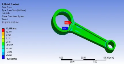
Figure 2: Shear stress for Al2O3
The figure 2 shows the shear stress distribution for Al2O3in connecting rod as per the given loading conditions. The maximum value is 13.029 MPa and minimum value is -10.652 MPa
Figure3: Total Deformation for Al2O3
The figure 3 shows the Total Deformation for Al2O3 in connecting rod as per the given loading conditions.
The maximum value is 1.3205e-002 MPa and
minimum value is 7.9893e-004 MPa
Comparing Al2O3 results with Forged steel and TiC:
Equivalent Stress (MPa)
Maximum Minimum
1 Forged
Steel 150.49 6.3787e-003
TiC 150.39 2.1105e-003
Al2O3 151.60 6.4095e-003
Shear Stress (MPa)
Maximum Minimum
1 Forged
Steel 12.983 -10.607
TiC 13.070 -13.638
Al2O3 13.029 -10.652
Total Deformation (MPa)
246
1 Forged
Steel 0.16823 1.092e-004
TiC 1.00390 8.3238e-004
Al2O3 0.013205 7.9893e-004
By comparing the above results we observe the following data:
1. Al2O3can withstand high equivalent stresses more than the other twomaterials.
2. Al2O3can take high shear stresses than the other twomaterials.
3. Al2O3has less deformation values than the other twomaterials.
So from the above results Al2O3is taken as the preferred material for connecting rod. Fabrication of prototype is carried out with Al2O3material. Then experimental texts are done on the prototype.
Fabrication with Al2O3:
Manufacturing of connecting rod includes: blanking, heating-roll, forging-closed, die forging, trimming, punching, heat treatment, shot blasting, correction.
1. To produce the connecting rod we will roll and extend the material first as we finish heating the material.
[image:6.595.312.522.257.363.2] [image:6.595.313.524.421.597.2]2. Figure 4 shows rolling of rod is done using Material RollerCR-150.
Figure 4: Rolling in CR-150
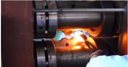
3. Figure 5 shows forging of connecting rod using forging PressFP-1000.
Figure 5: Forging of connecting-rod
4. The excess material is trimmed out using C-Series Pneumatic Press. Final forged product is obtained aftertrimming.
[image:6.595.75.284.566.676.2]247
Figure 6: trimming on lathe machine.
Figure 7: Final product (connecting rod)
Experimental results on Connecting rod:
The connecting rod experiences Tensile and
compressive or buckling loads in the combustion chamber. The tensile loads develop tensile stresses and compressive loads generate buckling stress.
Tensile Test:
1. Ultimate load of 26 KN is applied on the
connecting rod.
2. It can withstand the ultimate stress up to 4.9e+007 MPa.
3. Yield load of 30KN on connecting rod generates
yield stress of 4.79e+007 MPa.
Type of Load Value
Ultimate Load 26 KN
Ultimate Stress 4.9 e+007 MPa
Yield Load 30 KN
[image:7.595.76.283.440.615.2]Yield Stress 4.7 e+007 MPa
Figure 8: Tensile test on connecting rod
Buckling Test:
Specime n Input data
Value Force (N)
Buckle (mm)
Type flat 400 0.15
Width 17.72 mm 450 0.19
Thickness 8.63 mm 500 0.27
Material Al2O3 550 0.38
1. In this buckling test, the connecting rod fails at 550 N with a deflection of 0.38 mm
2. So, this Al2O3 prototype can take load up to 550
N which is more than the forged steel connecting rod.
3. Various buckling values at different
proportionate loads are withdrawn in a table.
4. A graph is plotted between Force and Deflection
[image:7.595.317.516.443.560.2]248
Figure 9: Buckling test on connecting rod
Graph plotted between Force Vs Deflection
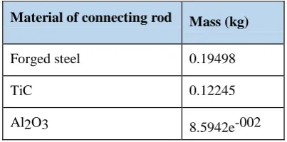
Weight reduction:
Material of connecting rod Mass (kg)
Forged steel 0.19498
TiC 0.12245
Al2O3 8.5942e-002
Weight reduction percentage:
Al2O3 = x 100 = 55.922 %
Results of Optimization:
Maximum (MPa)
Minimum (MPa) Equivalent
Stress 151.6
6.4095e-003
Shear Stress 13.029 -10.652
Total
Deformation 0.013205
7.9893e-004
From the above graphs and tables it is observed
that Al2O3 can withstand tensile and buckling load more than the forged steel and TiC.
Mass of the Al2O3 connecting rod is0.085942
Kg and the optimized geometry is 55.922 % lighter than the forged steel connectingrod.
By weight reduction and slightly more stress
with standing capacity of Al2O3, increases the life and performances of connectingrod.
Conclusion:
In this thesis, a broken connecting rod made of forged steel is replaced with Al2O3 and TiC. Static structural analysis is carried out to improve the fatigue life and performance by reducing the weight and stress in the connecting rod. Experimental tests are carried out and compared to the previous base journal. Optimization was performed to reduce weight of a forged steel connecting rod subjected to the elevated compressive gas load and the tensile load.
In order to optimize the stress of connecting rod we have changed some of its parameters and the stress level get reduced inAl2O3.
After comparing the Equivalentand Shear
stresses for Forged steel, Al2O3and TiC it is noted that the stresses are comparatively low in Al2O3, moderate in TiC and high in Forged steel for the given loadingconditions.
The Deformation values are low in Al2O3
compared to other twomaterials.
A weak and strong section of connecting rod is
verified and possible modifications have been done to correctit.
Some of the mistakes in reference data is being
corrected by us through calculation and analysis of connectingrod.
A comparison is also made between theoretical
249
factor of safety (factor of safety obtained inansys).
We could not bring a major change in the existingdesign.
The result obtained by us is nearly equal to the reference paper result and any change in this result is not very muchfavorable.
REFERENCE
[1] D. Gopinath and Ch. V. Sushma/Materials
Today: Proceedings 2 ( 2015 ) 2291 – 2299, Design and Optimization of Four Wheeler Connecting Rod Using Finite Element Analysis.
[2] Dongkai Jia ,KeWu,ShiWu, YuntongJia, Chao
Liang (2011) Global Conference on Electronic
and Mechanical Engineering and
InformationTechnology.
[3] The Manufacturing Engineering Society
International Conference, MESIC 2015 Procedia Engineering 132 ( 2015 ) 313 –318
[4] J.P. Fuertes et al. /Procedia Engineering 132 ( 2015 ) 313 –318.
[5] Journal of Materials Engineering and
Performance (Submitted April 7, 2015; in amended shape July 29,2016)• Isa MetinOzkara and Murat Baydog (2016)Optimization of Thixoforging Parameters for C70S6 Steel ConnectingRods.
[6] Mohammed Mohsin Ali Ha , Mohamed Haneef