IJEDR1502112
International Journal of Engineering Development and Research (www.ijedr.org)622
Implementation of Parallel Multiplier using Advanced
Modified Booth Encoding Algorithm
1Manthan J. Trivedi, 2Vimal H. Nayak, 3Mohmmed G. Vayada 1P.G. Student, 2Assistant Professor, 3Assistant Professor.
Electronics & Communication
Silver Oak College of Engineering & Technology (SOCET), Gujarat Technological University- Ahmedabad, India. ________________________________________________________________________________________________________
Abstract - This research paper represents the implementation of Advanced Modified Booth Encoding (AMBE) parallel Multiplier. The already existed Booth and Baugh Wooly Multipliers are used for only signed numbers, while array multipliers uses only for unsigned numbers. Modern Computer system needs a very high speed parallel multiplier which is used for signed and unsigned numbers. This multiplier is obtained by extending a sign bit from Modified Booth Encoder and generates an additional partial product; the proposed multiplier can be used for both signed and unsigned bits. The Carry Save Adder tree (CSA) and Carry Look Ahead Adder (CLA) are used to add all partial products and generates the final product. This multiplier uses for both signed and unsigned numbers so total chip area reduces and power reduces as well. The Advanced Modified Booth Encoding parallel multiplier for 8 x 8 bits signed-unsigned and 64 x 64 bits signed unsigned multiplier is simulated using Verilog-HDL language in Xilinx 13.2ISE simulator and implements on Spartan 3E starter board.
Index Terms - Modified Booth Encoding Multiplier, CSA, CLA, signed-unsigned numbers
________________________________________________________________________________________________________
I.INTRODUCTION
Multiplication is the most commonly used in every step of the world. It is nothing but the addition by the multiplicand adds multiplier no. of times. But, it takes very large hardware resources and simulation takes very large time for the final output. The main aim in VLSI field to make a multiplier which increase the speed and reduces the area and power. The multiplication mainly consists of two steps i) To generate Partial products and ii) To add all these partial products until the final output [1-7].
The High Speed Booth & Pipelined multipliers are used in DSP applications, like multimedia, FIR filter and communication system. Booth Algorithm provides multiplying binary integers in 2’s complement format and generates partial product by recoding the bits [4]. The numbers of partial products in Booth multiplier are equal to the numbers of multiplicand & multiplier bits. The Modified Booth Encoding Multiplier reduces the partial products by factor of 2 [2]. The main drawback of this multiplier was not using the sign bit, irregular partial product and used only for the signed numbers.
The Braun array multiplier also reduces the partial product to increase the speed of multiplier but it is used only for unsigned numbers [8]. So, in present system high speed multiplier which can perform on signed and unsigned number as well. So, Advanced Modified Booth Encoding Algorithm is being used for both signed and unsigned numbers.
II.MODIFIED BOOTH ENCODING ALGORITHM
IJEDR1502112
International Journal of Engineering Development and Research (www.ijedr.org)623
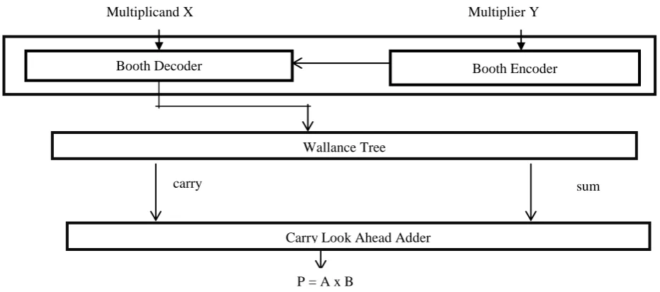
Figure 1 Architecture of Advanced Modified Booth Encoding AlgorithmFigure 1 represents the architecture diagram of Modified Booth Encoding parallel Multiplier. The inputs of the multiplier are X (Multiplicand) and Y(Multiplier). The Booth Encoder encodes the input Y and derives the encoded signals by overlapping of 3 bits {-2, -1, 0, 1, 2}. The Modified Booth Encoding Algorithm follows the below equation.
Value = -2×bi+1 + bi + bi-1 (1)
Equation 1 represents how the value of the encoder can be generated from 3 overlapping bits. The truth table for Modified Booth Encoder is shown below.
Table 1 Recoding Table of Modified Booth Encoder bi+1 bi bi-1 Value
0 0 0 0
0 0 1 1
0 1 0 1
0 1 1 2
1 0 0 -2
1 0 1 -1
1 1 0 -1
1 1 1 0
III. Proposed Advanced Modified Booth Encoding Multiplier (AMBE)
By extending a sign bit in the previous algorithm, an extra partial product is generated and to use for both signed and unsigned numbers. The AMBE also follows the same architecture diagram that have been shown in figure 1.There are Booth Encoder, Booth Decoder, Wallance Tree adder and Carry Look Ahead adder blocks are used. The Booth Encoder encodes the multiplier bits and generates the encoded signals {-2, -1, 0, 1, 2}.
Table 2 Truth Table of Advanced Modified Booth Encoding Algorithm
bi+1 bi bi-1 Value X1_a X2_a Z Neg
0 0 0 0 1 0 1 0
0 0 1 1 0 1 1 0
0 1 0 1 0 1 0 0
0 1 1 2 1 0 0 0
1 0 0 -2 1 0 0 1
1 0 1 -1 0 1 0 1
1 1 0 -1 0 1 1 1
1 1 1 0 1 0 1 0
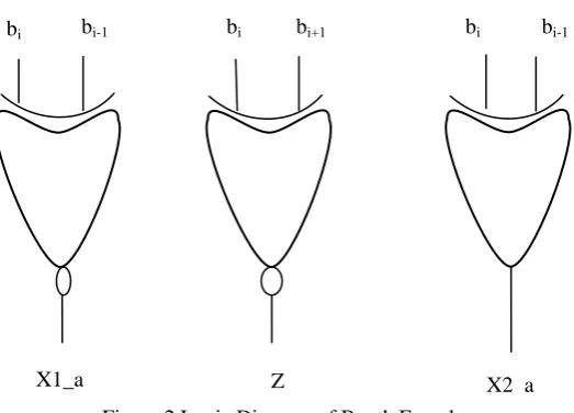
Table 3 represents the truth table of Advanced Modified Booth Encoding Parallel Multiplier. The Booth encoder encodes the the signals X1_a, X2_a, and Z. The logic diagram for Booth Encoder is shown in Fig.2.
Wallance Tree
Carry Look Ahead Adder
Booth Decoder Booth Encoder
Multiplicand X Multiplier Y
P = A x B
IJEDR1502112
International Journal of Engineering Development and Research (www.ijedr.org)624
Figure 2 Logic Diagram of Booth EncoderUsing MBE logic, Booth decoder generates the partial product bit which is given by Equation 2.
pij = (ai⊕bi+1+bi-1⊕bi) ( ai-1⊕bi+1 +bi⊕bi+1+ bi-1⊕bi ) (2)
Equation 2 is implemented as shown in Fig.3. The AMBE multiplier does not separately consider the encoder and the decoder logic, but instead implemented as a single unit called partial product generator as shown in Fig. 3. The negative partial products are converted into 2’s complement by adding a negate (Ni) bit. The Negative bit is represented by Equation 3. The Equation 3 is implemented as shown in Fig.4.The sign extension bit is converted to signed-unsigned number by Equations 4 and Equations 5. The logic Diagram of Equation 4 and Equation 5 are implemented as shown in Fig.5.
Ni = bi+1 (bi-1 bi ) (3)
a8 = s_u * a7 (4)
b8 = s_u *b7 (5)
bi bi-1 bi bi+1 bi bi-1
IJEDR1502112
International Journal of Engineering Development and Research (www.ijedr.org)625
Figure 3 Logic Diagram of 1-bit Partial Product Generator CircuitFigure 4 Logic Diagram of Negative bit Generator Circuit
Figure 5 Logic Diagram of Sign Extension bits
The sign Extension converter is used to convert signed multiplier into signed- unsigned multiplier by inserting s_u bit to indicate whether signed multiplier or unsigned multiplier. If s_u bit = 0, it indicates unsigned number multiplication. If s_u bit =1, it indicates signed number multiplication. It is very necessary that during unsigned multiplication, multiplicand and multiplier both are extended with 0 “i.e. a8=a9=b8=b9=0”. During signed multiplication, the sign extended bit depends on whether multiplicand is negative, multiplier is negative or both are negative. When the multiplicand is negative and multiplier is positive then a7=1, b7=0, s_u=1, a8=a9=1, b8=b9=0. When the multiplicand is positive and multiplier is negative then s_u=1, a7=0, b7=1, a8=a9=0, b8=b9=1.
a7
b7
s_u
a8
b8
bi-1 bi
bi+1
Ni bi
bi-1
bi+1 bi bi+1 bi-1 bi
ai ai-1 bi+1
IJEDR1502112
International Journal of Engineering Development and Research (www.ijedr.org)626
a7 a6 a5 a4 a3 a2 a1 a0b7 b6 b5 b4 b3 b2 b1 b0
p08 p08 p08 p07 p06 p05 p04 p03 p02 p01 p00 X1 1 p18 p17 p16 p15 p14 p13 p12 p11 p10 N0 X2 1---p20 N1 X3 1 ---p30 N2 X4 p47 p46 p45 p44 p43 p42 p41 p40 N3 X5
p15 p14 p13 p12 p11 p10 p9 p8 p7 p6 p5 p4 p3 p2 p1 p0 Figure 6 8x8 signed unsigned generated Partial Product bits
Figure 6 represents the partial products generated from Fig.3. There are 5 partial products and Negative bit generator. These partial products are X1, X2, X3, X4 and X5. These partial products are added by Wallance tree Adder which uses Carry Save Adder circuit. It adds partial products until final two outputs are left. Carry Save Adder (CSA) tree diagram is shown in Fig. 7 below. When there are only two outputs are left, Carry Look Ahead (CLA) Adder is used to do the final addition and give the Final product. Take each gate delay as an unit delay then including partial products, total delay is calculated as 3+4=7. During simulation in VLSI delay is calculated in nano second and operated on Giga Hertz frequency.
CSA 1
CSA 2
CSA 3
CLA
X1 X2
X3 X4
X5
P = A x B
IJEDR1502112
International Journal of Engineering Development and Research (www.ijedr.org)627
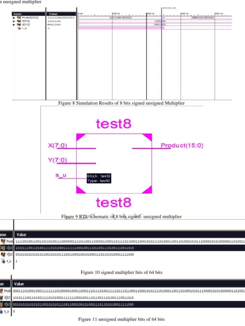
IV.SIMULATION RESULTSIn simulation Results, the test bench waveform and RTL schematic view of 8 bit proposed Advanced Modified Booth Encoding Parallel Multiplier is shown and 64 bits s_u multiplier bits is being shown below. If s_u=1 then it is signed multiplier and if s_u=0 then unsigned multiplier
Figure 8 Simulation Results of 8 bits signed unsigned Multiplier
Figure 9 RTL schematic of 8 bits signed- unsigned multiplier
Figure 10 signed multiplier bits of 64 bits
IJEDR1502112
International Journal of Engineering Development and Research (www.ijedr.org)628
Table 3 Observation TableParameter 8 bit proposed AMBE multiplier 8 bit MBE Multiplier Multiplier Type Signed and Unsigned Signed
Delay 28.172ns 27.182ns
No. of Slices 123 55
No. of 4 input LUTs 231 153
No. of Bounded I/Os 33 32
V.CONCLUSION
In this paper, the proposed Advanced Modified Booth Encoding Algorithm for 8 x 8 signed-unsigned algorithm and the 64x64 bits signed-unsigned multiplier bits. The delay (maximum combinational path delay), area(No. of slices, No. of bounded I/Os) can be calculated which has been reduced from Booth (Radix 2) algorithm.
REFERENCES
[1] ravindra p rajput, m. n shanmukha swamy,” high speed modified booth encoder multiplier for signed and unsigned numbers”,2012, 14th international conference on modelling and simulation, doi 10.1109/uksim.2012.99.
[2] Young-Hoseo & Dong-wook kim , a new vlsi architecture of parallel multiplier–accumulator based on radix-2 modified booth algorithm. ieee transactions on very large integration (vlsi) systems, vol. 18, no. 2, february 2010.
[3] Shiann-RongKuang, Jiun-Ping Wang, and Cang-Yuan Guo, “Modified Booth multipliers with a Regular Partial Product Array,” IEEE Transactions on circuits and systems-II, vol 56, No 5, May 2009.
[4] Nishant Bano, “VLSI Design of Low Power Booth Multiplier”, International Journal of Scientific & Engineering Research, Volume 3, Issue 2, February -2012, ISSN 2229-5518
[5] Jung-Yup Kang and Jean-Luc Gaudiot, “A simple high-speed multiplier design,” IEEE Trans. on Computers, vol. 55, issue 10, Oct. pp. 1253-1258, 2006.
[6] Li- Rung Wang, Shyh-JyeJou and Chung-Len Lee, “A well-tructured Modified Booth Multiplier Design” 978-1-4244-1617-2/08/$25.00 ©2008 IEEE.
[7] Shaikh Kailash Baba& D. Rajaramesh, “Design & Implementation of Advanced Modified Booth Encoding Multiplier”, International Journal of Engineering Science Invention ISSN (Online): 2319 – 6734, ISSN (Print): 2319 – 6726, Volume 2 Issue 8 August. 2013 PP.60-68.