University of South Carolina
Scholar Commons
Theses and Dissertations
2017
Multi-Axis Multi-Material Fused Filament
Fabrication with Continuous Fiber Reinforcement
Wout De Backer
University of South Carolina
Follow this and additional works at:https://scholarcommons.sc.edu/etd Part of theMechanical Engineering Commons
This Open Access Dissertation is brought to you by Scholar Commons. It has been accepted for inclusion in Theses and Dissertations by an authorized administrator of Scholar Commons. For more information, please [email protected].
Recommended Citation
Multi-Axis Multi-Material Fused Filament Fabrication with Continuous Fiber Reinforcement
by
Wout De Backer
Bachelor of Science
Delft University of Technology 2011
Master of Science
Delft University of Technology 2013
Submitted in Partial Fulfillment of the Requirements
for the Degree of Doctor of Philosophy in
Mechanical Engineering
College of Engineering & Computing
University of South Carolina
2017
Accepted by:
Ramy Harik, Major Professor
Michel van Tooren, Major Professor
Zafer Gürdal, Committee Member
Ioannis Rekleitis, Committee Member
Acknowledgments
The research presented in this dissertation is the product of more than three years
of dedicated work and was supported by many people. I wish to thank the
fol-lowing people for, without their guidance and support throughout the research, no
dissertation would exist. I am grateful and consider myself lucky to be surrounded
by such talented people who share my excitement for the research and educational
enrichment.
First and foremost, I would like to thank the main sponsor of this research,
TIGHITCO Inc., and their holding The Intertech Group. I would like to thank
Peter Nicholas, CEO of TIGHITCO Inc., for his belief in the technology and for the
continued financial support through the company and the investment of their project
engineer, Arturs Bergs, has allowed this project to grow to where it is today. Arturs
has lead the project on the industrial and commercialization side, and his efforts
continue to align the work with TIGHITCO’s vision, and with the broader industrial
community.
There were several other industry members and research partners that provided
support and that have allowed the impact of this research to grow. For the seedling
project that lead to the inverted robotic platform, I would like to thank Boeing R&T
Charleston. I would also like to thank Barry Hand, CEO of Reify, for providing
the opportunity to expand the technology to the prosthetics market. Furthermore, I
would like to acknowledge Hexcel for supplying the continuous fiber tows, and KVE
Composites for helping with the speedy acquisition of SABIC PEI pellets used in this
Izumi International for the tensioner creel and assistance with the tow impregnation
system and for the Smartstate Center for allowing the use of the TGA, DSC and
tube furnace equipment for this project. Thanks to Jim Miller and his colleagues
from KUKA for providing the technical support on the KUKA side. I wish to extend
my thanks also to Dr. Igor Luzinov and his student Nick Borodinov from Clemson
University for their initial work on the impregnation, an idea incepted by Dr. van
Tooren.
A sincere thank you to the supporting staff at the McNAIR Center, in
particu-lar, Burton Rhodes for overall lab management, support and processing of the many
purchasing orders. Also to Adrianne Beasley for her role in enrollment and contract
related aspects of this project. I would like to sincerely thank my advisors Dr. Ramy
Harik and Dr. Michael van Tooren, who has been the PI of the project, for
pro-viding me with excellent constructive feedback and assistance on my work and for
keeping myself and the project on the right path. I always returned encouraged and
enlightened from our meetings and your connections to other academics, potential
investors and research partners, together with your initial investments from your
per-sonal start-ups have given this project many opportunities to grow. I would also like
to thank Dr. Zafer Gürdal and Dr. Joshua Tarbutton for starting the 3D printing
with continuous fiber research and for their initial work at USC.
The experimental work done in this research was accelerated significantly from
the number of undergraduate and graduate students that have volunteered through
the McNAIR Junior Fellowship program, and the staff that was part of the full-time
team. In particular, I would like to thank: Aaron Smith for his work on material
impregnation and liquefier development, Cody Carter for his effort on the
monofila-ment extruder, Max Kirkpatrick for his work on the software developmonofila-ment and path
optimization, Sean Doherty for his developments on the 3D slicer, Connor Frailey
pa-pers, Royal D’Cunha for his work on operating and testing the technology on the
3-axis system, Carl Chandler for his general assistance to the project and many other
volunteers that contributed to the printing lab operations.
Last but certainly not least, I wish to thank my friends and colleagues here in
Columbia, for surrounding me in a motivating environment dominated by a healthy
working mentality. I would also like to thank Angi Wang, my girlfriend, for all her
love, support and for patiently bearing with me as the nights in the lab got longer
and longer over the months. I owe my deepest gratitude to my family in Belgium for
their continuous support that has brought me to USC, to complete this research and
for teaching me that hard work pays off.
The building and strengthening of these partnerships and the progress and value
from the research would not have been possible without the original vision of the
McNAIR Center’s initial three donors: Darla Moore, Anita Zucker and Marva Smalls.
Their generous investment is continuing to build a strong aerospace presence at USC
and the students and research performed here in South Carolina is benefiting the
Abstract
Additive Manufacturing (AM) has become a well-recognized method of
manufactur-ing and has steadily become more accessible as it allows designers to prototype ideas,
products and structures unconceivable with subtractive manufacturing techniques for
both consumer grade and industrial grade applications. Commonly used
thermoplas-tics for 3D printing have properties that may not be sufficient to comply with the
application’s certification requirements, or their performance is less than desirable for
aerospace and other high performance applications. Additionally, additively
manu-factured parts have reduced mechanical properties in the build direction of the print,
and are generally weaker than their equivalent injection-molded parts. Furthermore,
Computer Aided Design and Manufacturing (CAD/CAM) tools have evolved together
with the evolution of processes for subtractive and deformative based manufacturing
methods, and ply-based additive composite manufacturing. For AM to gain more
traction in industrial engineering environments, the process specific algorithms for
AM need to be implemented in CAD/CAM software. There is therefore a need for
reinforcement of both the material and the structures, and for proving the
indus-trial capabilities of additive manufacturing, in particular fused filament fabrication,
through a new set of processes that complement the existing design paradigm. A
promising solution to the above mentioned problems of strength is using engineering
thermoplastics and through the addition of continuous carbon fibers in the print.
Un-fortunately, engineering-thermoplastic impregnated continuous carbon fiber filaments
for 3D printing do not exist due to the low demand and pure filament is currently
in the inter-layer direction may come through the addition of local reinforcement
de-posited on an existing structure in the build direction, which implies stepping away
from layer-by-layer manufacturing and manufacturing using true 3D deposition and
toolpathing. This is only possible by exploiting the full benefits of a 6 or higher
degree of freedom printing system.
In this research, a KUKA robotic platform capable of motion with 6 degrees
of freedom is used as a base to develop a multi-axis, industrial-scale 3d printer.
Polyetherimide (PEI), an engineering thermoplastic sold under the Sabic brandname
ULTEM 1000 was acquired in pellet form and extruded within tolerances into a usable
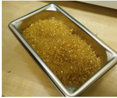
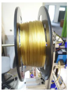
3D printing filament. ULTEM 1000-Continuous Carbon Fiber filament was developed
by dissolving the ULTEM 1000 pellets in a solution bath and consequently pulling
the carbon fiber through it. A specialized nozzle design and printing bed capable of
going up the required processing temperatures was developed and integrated with the
KUKA platform, for which specialized toolpathing software was written. The
tool-pathing software consists of two subsets: a slicing tool that allows multi-orientation
slicing, and a translation parser which converts the G-code toolpath commands into
KUKA-format KRL. The slicing tool uses Stereo lithography-format (STL)
triangu-lated mesh files to generate slices of toolpathing for a geometry, which is then modified
to add toolpathing for both global and local features with multi-orientation slicing
techniques. In this way, compound objects can be sliced without the restrictions of
common slicers. Designed for use with the broad range of capabilities of modern
industrial robotics, a 6-axis directional reinforcement can thus be added to various
types of base geometries. In addition to syntax modification, the translation parser
also detects insignificant and collinear commands in the G-code and converts groups
of points representing a discretized arc into a higher-order arc-command. Repeated
sections in the code are also collapsed into a for-loop structure. This significantly
The in-house developed printer was used to print coupons for a multitude of ASTM
tests to evaluate the mechanical performance, including longitudinal and transverse
tensile and compression tests, shear and interlaminar shear tests. Specimen were also
subjected to in-house Thermo-Gravimetric Analysis (TGA) and Differential
Scan-ning Calorimetry (DSC) tests to determine the chemical characteristics, and a range
of other methods were used to identify fiber-volume ratios, void-volume ratios and
surface quality of the pellets, filaments and printed parts. Furthermore, two
configu-rations of the printer were assessed: one where the bed is the KUKA end effector and
the nozzle is stationary, and one where the nozzle is the KUKA end effector and the
bed is stationary. A prototype of a 7th axis, and initial toolpathing was added to the
system to allow full rotational freedom expanding the robots operating envelope and
complexity of the printed parts. Beyond the printer development, toolpathing
devel-opment, material development and testing, several industrial components for funding
partners were printed as a proof of concept and for marketing purposes,
demonstrat-ing the technology readiness of this process. The methods, processes and results
discussed in this paper are developed with certification in aerospace in mind, and
they show great promise for the implementation of functional additive manufacturing
Table of Contents
Acknowledgments . . . iii
Abstract . . . vi
List of Tables . . . xiii
List of Figures . . . xiv
Chapter 1 Introduction . . . 1
1.1 Problem Background . . . 1
1.2 Problem Statement . . . 3
1.3 Purpose of the Study . . . 7
1.4 Hypotheses . . . 8
1.5 Significance of the Study . . . 10
1.6 Research Scope . . . 11
1.7 Dissertation Outline . . . 13
Chapter 2 State of the Art & Framework . . . 15
2.1 Industrialization of 3D Printing . . . 16
2.2 Additive Manufacturing & Integral Design . . . 18
2.3 State of the Art of Fused Filament Fabrication . . . 21
2.5 Toolpath Generation & Software Development . . . 34
2.6 Characterization of FFF 3D Printing . . . 48
2.7 Framework for Reinforced Multi-Material AM . . . 50
2.8 Conclusion . . . 66
Chapter 3 Material Formatting . . . 69
3.1 Manufacturing of Monofilament . . . 69
3.2 Impregnated Carbon-Fiber Filament . . . 81
3.3 Conclusions . . . 99
Chapter 4 Fused Filament Fabrication using Continuous Fibers 101 4.1 Printing Technology Development . . . 102
4.2 In-Situ Manufacturing Monitoring during FFF . . . 130
4.3 Experimental Verification Platforms . . . 137
4.4 Notes on Print Quality and Post-Processing . . . 144
4.5 Conclusions & Recommendations . . . 150
Chapter 5 Toolpath Planning, Simulation & Integration for Industrial Robotics . . . 152
5.1 Slicing & 3D Printing Toolpath Planning . . . 153
5.2 Reconstruction of Motion from G-Code Patterns . . . 154
5.3 Build Orientation Determination for FFF with CF . . . 162
5.4 Toolpath Planning for Multi-Axis 3D Printing . . . 174
5.5 Application to Industrial Robotics . . . 204
5.7 Conclusions & Recommendations . . . 221
Chapter 6 Characterization & Quality Control. . . 223
6.1 Characterization of AM Processes . . . 224
6.2 Visual & Optical Inspection . . . 231
6.3 Mechanical Testing . . . 239
6.4 Density Measurements . . . 244
6.5 Chemical and Physical Composition Testing . . . 245
6.6 Conclusion . . . 248
Chapter 7 Conclusion & Future Work . . . 250
7.1 Review of the Hypotheses . . . 250
7.2 Research Perspective . . . 254
7.3 Future Development Opportunities . . . 256
7.4 Conclusion . . . 259
Bibliography . . . 261
Appendix A Sample Code . . . 278
A.1 G-code Program Sample . . . 278
A.2 KUKA KRL Program Sample . . . 279
A.3 KUKA KRL Program with External Axis Sample . . . 280
A.4 KUKA KRL Program with Pause Functionality Code Sample . . . . 280
A.5 MACFAM Slicer Program Sample . . . 280
A.7 Modifications to the KUKA Config (config.dat) . . . 283
List of Tables
Table 4.1 Relative material feed rates for various geometries for a
contin-uous fiber inflow of≈ 5 mm/s . . . 121
Table 4.2 Various bed surfaces and their adhesion performance rating . . . . 125
Table 4.3 Key performance parameters of the current systems and their
acceptable limits . . . 127
Table 5.1 Results from the optimization showing a clear and significant
reduction in the number of path commands . . . 161
Table 5.2 Criterion evaluation values of alternative build orientations.
Support volume is measured in [mm filament used]. . . 172
List of Figures
Figure 1.1 The web of technologies related to industrial 3D Printing with
continuous fiber . . . 4
Figure 1.2 Common composite manufacturing methods at the McNAIR
Center: (1.2a) VARTM of two skin panels for a UAV and (1.2b)
Automated Fiber Placement. . . 5
Figure 1.3 Gartner’s 2012 Hype Cycle for Emerging Technologies[121] . . . . 8
Figure 1.4 The scope of the research spans all pre- and post-processing
steps required for quality printing with continuous fibers. . . 12
Figure 2.1 Schematic representation of influences to the design process
[161, p. 17]. . . 19
Figure 2.2 An exponential increase in the number of parts shows the need
for integral manufacturing to reduce assembly costs [161, p. 67]. . 19
Figure 2.3 Sketchpad [148]. . . 20
Figure 2.4 Different variations of 3D printing, adapted from [177],
origi-nally [77]. . . 22
Figure 2.5 Tensile strength of various 3D printing processes [177], adapted
from [154]. . . 23
Figure 2.6 Current developments in continuous fiber 3D printing . . . 23
Figure 2.7 Classification of Thermoplastics [91] . . . 26
Figure 2.8 Influence of process and material parameters on polymer
vis-cosity [167] . . . 29
Figure 2.9 Extruder screw geometry directly affects melt processing
Figure 2.10 Experimental Sizing Line: 1-Unwinding Mechanism, 2 - Ten-sioning Unit, 3 - Bath, 4 - Sprayer, 5 - Drying box, 6 - Drawing mechanism, 7 - Winding Mechanism, 8 - Motor and speed
con-trol, 9 - Circulation Reservoir [152] . . . 34
Figure 2.11 Conventional workflow for the slicing operations in 3D printing. . 35
Figure 2.12 The same tool coordinate system location and orientation can be obtained with different solutions for the manipulator orien-tation, which may not always be possible: (2.12a) A photo of the KUKA KR6 R700 Sixx, (2.12b) Abstract representation of the robot and its axes in two different configurations, (2.12c) Although the two configurations have the same tool coordinate
orientation, they are not always possible or desirable. . . 38
Figure 2.13 Illustration of a probabilistic roadmap with obstacles and an
optimal path[21, p. 207] . . . 41
Figure 2.14 Some variations of RRT can be seen as Stochastic Fractals: the central node is the starting configuration, and the tree grows
from there to find the optimal solution[159] . . . 41
Figure 2.15 Novel methods in toolpathing and mesh analysis: (2.15a)
CLFDM methods may be applied to allow deposition on non-planar surfaces [15], (2.15b) Toolpath and deposition orientation determination can be extracted from Prominent
Cross-Sections (PCS) and skeleton analysis [137]. . . 48
Figure 2.16 Prediction of printer performance: (2.16a )The ORNL Printed Car - Strati [87], (2.16b) Likely locations of crack initiation due
to thermally induced residual stresses [151]. . . 49
Figure 2.17 An Example of Multi-Material Topology Optimization for a
heat conduction problem [191]. . . 53
Figure 2.18 Improvement in mechanical properties through the addition of continuous reinforcement in Additive Manufactured parts and
a representation of the reinforcement within the design tool [98]. 54
Figure 2.19 Open-loop vs. PI closed-loop circle tracking: (left) Raw
trajec-tories, (right) Tracking error amplified radially 20 times. [171] . . 56
Figure 2.20 Manufacturing deviation for a 3D printed part with a layer
Figure 2.21 Building-block approach of considerations for the part design process 58
Figure 2.22 Sample of the part design process for additive manufacturing, which includes material allocation optimization and evaluation
through one or more objective functions . . . 60
Figure 2.23 Qualitative example of the optimization process . . . 62
Figure 2.24 Examples of current 5-axis and 6-axis additive manufactur-ing hardware: (2.24a) A turntable 3D printer[55], (2.24b) the Mataerial 3D Printer[71], (2.24c) the 5axisMaker Printer[1], and (2.24d) the Arevo Labs 6 axis Printer[88]. . . 65
Figure 2.25 Qualitative example of a designed part with selective reinforce-ments, from design space or envelope to final, topology opti-mized shape with material allocation . . . 65
Figure 3.1 Barrel Type Extruder[65] . . . 71
Figure 3.2 Plunger Type Extruder[65] . . . 71
Figure 3.3 PEI Pellets . . . 73
Figure 3.4 Foamy Filament . . . 73
Figure 3.5 Drying oven . . . 74
Figure 3.6 Metal Filastruder . . . 74
Figure 3.7 The micro-compounder set-up . . . 74
Figure 3.8 The original extrusion set-up . . . 75
Figure 3.9 Cloudy filament (right) . . . 75
Figure 3.10 Quality filament . . . 75
Figure 3.11 Schematic representation of the monofilament production setup (Not to scale) . . . 76
Figure 3.12 PEI Monofilament imperfections and quality . . . 78
Figure 3.14 A 251m spool of PEI monofilament produced in-house . . . 79
Figure 3.15 Sample of diameter results for 20 meter of in-house produced PEI monofilament, compared to the acceptable upper and lower limits . . . 80
Figure 3.16 Representation of fiber bundle impregnation . . . 84
Figure 3.17 Normalized fill time vs. normalized fill radius . . . 84
Figure 3.18 Methods of measuring viscosity: Velocity-force relation between flat plates and Torque-rotation rate relation in the cone-and-plate rheometer . . . 84
Figure 3.19 Shear Rate vs. Shear Stress . . . 85
Figure 3.20 PEI Conc. vs. Viscosity . . . 85
Figure 3.21 Solvent/liquid impregnation methods [103] . . . 89
Figure 3.22 Representation of the initial impregnation setup at Clemson Univ. (not to scale) . . . 91
Figure 3.25 Impregnation Bath . . . 91
Figure 3.26 Initial in-house setup . . . 91
Figure 3.23 Results from impregnation trials: (3.23a) Dry 3K hexcel hextow fiber, (3.23b) initial trials at Clemson University, (3.23c) initial trials from the first in-house system at USC, and (3.23d) after system optimization at USC . . . 92
Figure 3.24 Schematic representation of the original impregnation setup (Not to scale) . . . 92
Figure 3.27 Schematic representation of the impregnation setup (Not to scale) 93 Figure 3.28 The latest iteration of the impregnation system . . . 95
Figure 3.29 Sizing Bath . . . 95
Figure 3.30 Impregnation roller configuration . . . 95
Figure 3.32 Results from coating trials: (3.32a) using the Clemson trial
impregnated fiber, (3.32b) using the optimized USC fiber . . . 97
Figure 3.33 Continuous 3K carbon fiber filament respooled without (3.33a) and with adding extra monofilament (3.33b and 3.33c) . . . 97
Figure 3.34 Effect of filament quality: (3.34a) print with flaky filament and (3.34b) print with consistent filament . . . 98
Figure 3.35 Recent microscopy results: (3.35a) Unsized respooled filament, (3.35b) sized respooled filament . . . 98
Figure 4.1 The tension along the fiber during printing . . . 104
Figure 4.2 Feedback on the continuous fiber filament feed can prevent print failure due to bunching of the fibers in the liquefier . . . 105
Figure 4.3 The effect of tension on the fiber within the deposition . . . 106
Figure 4.4 Annotated photo of the current end effector . . . 107
Figure 4.5 Deviation from deposition path due to tension . . . 108
Figure 4.6 Effect of tension inconsistencies on wall surface roughness . . . 108
Figure 4.7 Bridging during 3D printing, with and without (tensioned) con-tinuous fiber . . . 109
Figure 4.8 Example prints of bridging in parts, demonstrated successfully for bridges spanning 40mm and 120mm . . . 110
Figure 4.9 Printing of overhang structures with continuous fiber . . . 111
Figure 4.10 Liquefier and nozzle geometry, extrusion and feed rate highly influence temperature profile of the printing material . . . 114
Figure 4.11 The internal geometry of the liquefier . . . 115
Figure 4.12 The base nozzle and modification tools used . . . 117
Figure 4.13 The liquefier and nozzle assembly with E3D heatbreak and Printrbot gear head monofilament extruder system . . . 117
Figure 4.15 Replaceable liquefier insert . . . 118
Figure 4.16 Deviations from optimal liquefier temperatures affects the print quality: (4.16a) surface roughness from bubbling due to exces-sive liquefier temperature, (4.16b) optimal liquefier temperature
and (4.16c) imperfections due to insufficient liquefier temperature 119
Figure 4.17 Nozzle cooling . . . 123
Figure 4.18 Effect of nozzle cooling on temperature gradients . . . 123
Figure 4.19 Nozzle cooling systems on the two in-house printers . . . 123
Figure 4.20 Parts printed with excessive nozzle cooling can easily be pulled
apart . . . 123
Figure 4.21 Bed levelness heavily affects first layer adhesion and thus the print quality: Well leveled bed ((a) and (b) top) and poorly
leveled bed ((a) and (b) bottom) . . . 126
Figure 4.22 The cutting and restart procedure for continuous fiber 3D printing 129
Figure 4.23 Prototype grabbing and cutting system . . . 130
Figure 4.24 Nesting of objects on a bed to reduce printing cycle time . . . 132
Figure 4.25 Plastic ”spaghetti” created after print failure . . . 132
Figure 4.26 The proposed process of in-situ manufacturing monitoring
dur-ing 3D printdur-ing . . . 132
Figure 4.27 Sample coding structure for an in-situ monitored manufactured
object . . . 136
Figure 4.28 The MendelMax 3 . . . 138
Figure 4.29 The MACFAM Mini control panel . . . 138
Figure 4.30 The MACFAM Mini fitted with the continuous fiber end effector
and its control board . . . 139
Figure 4.31 ABS Plastic parts printed on Vesuvius with an E3D V6 hot end . 140
Figure 4.33 Sample prints (left to right, top to bottom): Simple hollow
cylinder and stadium, brackets, y-shaped tube. . . 141
Figure 4.34 Sample prints (left to right, top to bottom): Square with shell, grid infill, large prosthetic socket, windmill and rocket fins . . . . 142
Figure 4.35 Demonstration of set-up and capability of printing on printed surfaces . . . 143
Figure 4.36 Demonstration of support material prints: (4.36a) Different ma-terials tested (left to right: PLA Pro, PC, HIPS, PLA Pro) and (4.36b) surface finish after removal from support material . . . 144
Figure 4.37 Post-processing can leave a mirror-like surface finish . . . 145
Figure 4.38 Effects of sanding: (4.38a) Original, (4.38b) after sanding with 120 grit paper (4.38c) after sanding with 220 grit paper and (4.38d) after sanding and polishing with 600 grit paper . . . 146
Figure 4.39 Chloroform vapor trial setup . . . 147
Figure 4.40 Chloroform vapor treatment trials: (4.40a) untreated specimen (4.40b) smoothened and (4.40c) overexposed specimen . . . 148
Figure 4.41 Vapor chamber post-processing setup . . . 148
Figure 4.42 Post-processing through brush-on solution application . . . 149
Figure 4.43 Untreated printed surface . . . 149
Figure 4.44 Effect of various brush-on post-processing solutions: (4.44a) after application of 75 strokes of chloroform, (4.44b) after ap-plication of 20 strokes of 3% PEI and chloroform solution and (4.44c) after application of 10 strokes of≈15% PEI and chloro-form solution . . . 149
Figure 4.45 Microscopic effects of various brush-on post-processing solu-tions: (4.45a) after application of 75 strokes of chloroform, (4.45b) after application of 20 strokes of 3% PEI and chloroform solution and (4.45c) after application of 10 strokes of≈15% PEI and chloroform solution . . . 150
Figure 5.2 Collinear movements that can be concatenated into a single command: (5.2a) The first command, (5.2b) The second com-mand, and (5.2c) The concatenation of the two commands into
one command. . . 157
Figure 5.3 Movement commands and their resulting concatenation: (5.3a)
An unnecessary short movement command, (5.3b) The concate-nation of that movement command with the long movement command trailing it and (5.3c) A set of linear movement
seg-ments that can be converted into a single arc movement. . . 158
Figure 5.4 The optimizing of a stadium toolpath: (5.4a) The desired
ge-ometry, (5.4b) An example of an original toolpath, (5.4c) One layer from the original G-Code with sufficient linear movements to approximate the curves, (5.4d) One layer of the optimized path with 2 linear commands and 2 arc commands and (5.4e)
Representation of the optimized toolpath code including a for-loop. 159
Figure 5.5 From left to right: (5.5a) Example of the scope of the
post-processing workflow with the in-house developed G-code opti-mizer, (5.5b) The Mendel Max 3, an off-the-shelf 3D printer controlled by G-code and (5.5c) An in-house developed 3D Printer based on a KUKA Robotic platform used to run the
converted code, controlled by KRL-code. . . 160
Figure 5.6 Examples to test the optimization algorithms: (5.6a) Stadium,
(5.6b) Cylinder, (5.6c) S-Tube, (5.6d) Y-Tube, (5.6e) Vase,
(5.6f) Complex 1 and (5.6g) Complex 2. . . 161
Figure 5.7 Testing the optimized robot code: (5.7a & 5.7b) The stadium
geometry 3D printed on the KUKA setup proving the successful
translation of G-Code to optimized KRL. . . 162
Figure 5.8 The new composite AM experimental setup and mechanism . . . 164
Figure 5.9 Orientation Optimization Method . . . 166
Figure 5.10 Generation rules for three shape feature unit types (arrows
in-dicate alternative build orientations) . . . 166
Figure 5.11 A slice with disconnected deposition areas and sharp corners . . . 168
Figure 5.12 Z-size-error in fixed fiber layer deposition . . . 170
Figure 5.14 Refined alternative orientations for the STL model . . . 172
Figure 5.15 State of the art 5 or 6 axis fused deposition modeling systems: (5.15a) A 5 Degree of Freedom 3D Printer [55], (5.15b) a noz-zle end effector mounted to an industrial robot [71], (5.15c) The in-house 6 degree of freedom printer in development at USC, (5.15d) a 5-axis CNC milling machine outfitted
additive-subtractive capabilities [143]. . . 175
Figure 5.16 Example of building a compound geometry:(5.16a) The base feature with build direction along the Z-axis, (5.16b) the base feature with imposed trace of extrusion feature, (5.16c) the ex-trusion feature with build direction along the Y-axis and (5.16d)
finally, the compound geometry. . . 178
Figure 5.17 Conventional slicing (light colored) and new (dark colored)
op-erations in 3D printing toolpath generation flow. . . 179
Figure 5.18 Stiffener generation: (5.18a) the base geometry with (5.18b)
uncorrected and (5.18c) normal-corrected tool orientation. . . 183
Figure 5.19 The complete workflow of extrusion and stiffener toolpath
gen-eration on top of a base geometry. . . 184
Figure 5.20 Compound geometry generated with the toolpath generator: (5.20a) The full multi-planar deposition toolpath, (5.20b) a sec-tion of the toolpath containing the transisec-tion and (5.20c) A close-up of the out-of-plane support showing the different
ori-entation of the toolpaths. . . 184
Figure 5.21 Compound geometry generated with the toolpath generator: (5.21a) The design model from CATIA, (5.21b) The full multi-planar deposition toolpath, (5.21c) The extruded feature and
(5.21d) A close-up showing the different orientation of the toolpaths.185
Figure 5.22 Stiffened cylinder generated with the toolpath generator: (5.22a) The CAD-Defined geometry, (5.22b) The base geom-etry, (5.22c) The stiffener toolpath, (5.22d) The highlighted stiffened geometry and (5.22e) A close-up of the stiffener
showing the different toolpath orientations. . . 186
Figure 5.23 A randomly stiffened vase generated with the toolpath gener-ator: (5.23a) The CAD model, (5.23b) the stiffened geometry
Figure 5.24 Stiffened, compound geometry generated with the toolpath generator: (5.24a) The CAD Model of the compound object, (5.24b) The base features, (5.24c) & (5.24d) The compound toolpath and (5.24e) A close-up of the stiffened section showing
the different toolpath orientations. . . 186
Figure 5.25 Toolpath generation process: (5.25a) The base model, (5.25b) offset surface, (5.25c) intersection surface, (5.25d) The path
splines, and (5.25e) autogenerated equidistant points. . . 189
Figure 5.26 Layer height definitions for non-orthogonal printing: (5.26a) constant layer height for compound geometry on flat base
sur-faces, and (5.26b) curved base surfaces. . . 190
Figure 5.27 Visualization of multi-material in the in-house developed slicer: (5.27a) Three different tools and (5.27b) Two different tools
with a multi-axis compound feature. . . 191
Figure 5.28 Multi-Material demonstration prints on the KUKA printer: (5.28a), (5.28b) & (5.28c) Two different PLA colors being printed by layer and within layers and (5.28d) Printed component partially reinforced with carbon fiber and partially
unreinforced with pure PEI material. . . 192
Figure 5.29 Turntable and Mandrel Setups: (5.29a) the turntable on the HAAS V-5/50 CNC Mill and (5.29b) the Mandrel of the
Inger-soll AFP at McNAIR. . . 192
Figure 5.30 Turntable orientation options . . . 193
Figure 5.31 Normal selection: (5.31a) nearest facet centroid, (5.31b) nearest
vertex (5.31c) nearest plane. . . 196
Figure 5.32 Normal visualization: (5.32a) Normals on a highly tessellated
tube (5.32b) Normals on a complex surface. . . 197
Figure 5.33 Twisting in the deposited tow (corners) due to the local tool
orientation . . . 199
Figure 5.34 Global tool orientation . . . 200
Figure 5.35 Steered tool orientation . . . 200
Figure 5.37 Tool steering sample . . . 200
Figure 5.38 Local tool orientation . . . 201
Figure 5.39 Turntable orientation . . . 203
Figure 5.40 Turntable sample path . . . 203
Figure 5.41 Euler Angles calculated from orientations: (5.41a) Rotation in
X (C angle)(5.41b) Rotations in X and Y (B and C angles). . . . 205
Figure 5.42 The KUKA System Architecture . . . 206
Figure 5.43 The Workvisual interface showing the EtherCAT fieldbus struc-ture, the mapping of inputs and outputs and the communication
values . . . 208
Figure 5.44 The KUKA Sim Pro interface showing the Vesuvius setup . . . . 210
Figure 5.45 The RoboDK interface showing the Etna setup . . . 211
Figure 5.46 The second KUKA platform printer: Etna . . . 214
Figure 5.47 The KUKA HMI . . . 215
Figure 5.48 Extrusion dials and pause button . . . 215
Figure 5.49 Status LED’s . . . 215
Figure 5.50 System temperature PID controllers . . . 215
Figure 5.51 The CAD model for Vesuvius . . . 216
Figure 5.52 The CAD model for Etna . . . 216
Figure 5.53 The configuration of Etna was selected to yield the largest print
volume . . . 217
Figure 5.54 Action radii of the Etna end effector: (5.54a) side view and
(5.54b) front view. . . 218
Figure 5.55 The Etna end effector with the carbon fiber nozzle (1), and two
plastic extrusion nozzles, nozzle 2 (2) and nozzle 3 (3) . . . 219
Figure 5.57 This mandrel designed for Etna can accommodate a 2m long part 220
Figure 5.58 Multi-base print sample . . . 221
Figure 5.59 Multi-Axis print samples . . . 221
Figure 6.1 The full, unreduced stress state of a laminate[161, p. 67]. . . 226
Figure 6.2 Typical lamina definition for use in CLT . . . 226
Figure 6.3 Levels of unit cells: (6.3a) strand level, (6.3b) deposition level,
(6.3c & 6.3d) Multiple depositions in one cell . . . 227
Figure 6.4 Finite Element Modeling of 3D Printed Parts: (6.4a) A sample
geometry, (6.4b) a Low-fidelity mesh and (6.4c) a High-Fidelity
mesh . . . 228
Figure 6.5 Crack modeling of two adjacent depositions . . . 229
Figure 6.6 Crack modeling of two non-parallel depositions . . . 229
Figure 6.7 Deposition Spacing . . . 230
Figure 6.8 Qualitative estimate of the effect of deposition spacing on stress
and strain allowables . . . 230
Figure 6.9 Deposition Height . . . 230
Figure 6.10 Qualitative Estimate of the Effect of Deposition Height on
Stress and Strain . . . 230
Figure 6.11 Deposition Strategies affect material orientation and therefore
need to be accounted for and defined in the design stage . . . 232
Figure 6.12 Significant variations in ”stacking” orientation are unique to the
6-axis FFF manufacturing . . . 232
Figure 6.13 Some of the used microscopy samples: filament (left) and part
sections (right) . . . 235
Figure 6.14 Continuous 3K carbon fiber filament impregnated at low (6.14a)
and higher tension (6.14b) . . . 235
Figure 6.16 Annotated Microscopic Filament . . . 236
Figure 6.17 Impregnation quality can be detected from void content:
(6.17a) poorly impregnated filament and (6.17b)
semi-impregnated filament . . . 236
Figure 6.18 Solid part microscopy: (6.18a) the inspected part, (6.18b) cross
section, and (6.18c) detail . . . 237
Figure 6.19 Primary defects in single walled parts: (6.19a) Fiber pullout,
(6.19b) voids, and (6.19c)fiber corner bridging . . . 238
Figure 6.20 Microscopy of ASTM coupons: (6.20a) Transverse coupon
sec-tion and (6.20b) Longitudinal coupon secsec-tion . . . 238
Figure 6.21 Two sections used to demonstrate the profilometry of a
contin-uous fiber 3D printed part . . . 239
Figure 6.22 The profile of the two sections shown in figure 6.21 (left profile
is top) . . . 239
Figure 6.23 Longitudinal and transverse tensile printed test specimen . . . 241
Figure 6.24 Longitudinal and transverse deposition strategies[84] . . . 241
Figure 6.25 Shear specimen deposition strategy[8] . . . 242
Figure 6.26 Modulus and offset strength determination[8] . . . 242
Figure 6.27 Printed specimen to determine the shear modulus and strength . 242
Figure 6.28 Failure modes of the prints . . . 243
Figure 6.29 Comparison of the tensile strength with baselines[156][94][134] . . 243
Figure 6.30 Comparison of the tensile modulus with baselines[156][94][134] . . 243
Figure 6.31 Typical Stress-Strain curve of the longitudinal tensile specimen . 244
Figure 6.32 Immersion setup . . . 245
Figure 6.33 Comparison of the density with baselines[156][94][134] . . . 245
Figure 6.34 Fiber and void volume ratios throughout the filament
Figure 6.35 Results from TGA: PEI Pellets (dotted), PEI Filament
(Dash-dot) and Printed part (Bold) . . . 247
Figure 6.36 DSC Results: PEI Pellets (top), PEI filament (middle) and
printed part (bottom) . . . 248
Figure 7.1 Applications: a quadcopter UAV (7.1a) with printed arms
(shown separately in 7.1b) . . . 256
Figure B.1 Heater PID wiring diagram . . . 285
Figure B.2 PLC connections from the KUKA Extension Bus (1) . . . 285
Chapter 1
Introduction
In this chapter, the context, limitations and purpose of the research are introduced.
The background context and environment of the research performed is situated in
section 1.1. The resulting problem statement and purpose of the study are elaborated
on in section 1.2 and 1.3. The hypotheses this research seeks to prove are listed in
section 1.4, whereas section 1.5 details the significance of proving these hypotheses.
The scope of the research, together with a top-level view of the logical flow in this
research is presented in section 1.6. Finally, an outline of this dissertation is presented
in section 1.7.
1.1 Problem Background
In an ever-increasingly competitive world, businesses are continuously looking to
in-crease their profit margins, and one of the methods to do this is to reduce the
non-recurring expenses. This also holds for companies in the high-tech manufacturing
fields, such as aerospace, automotive or medical fields. In manufacturing industry,
the most significant non-recurring cost contributors are the cost of engineering, tools
and fixtures. For low-volume parts, the cost addition of the non-recurring aspects
can surmount those of the recurring costs. As such, the cost of tooling can far exceed
the component cost, which is especially true in composite manufacturing, where tools
often have to withstand elevated autoclave curing temperatures and pressures while
maintaining tolerances. This is where tool-less out-of-autoclave Additive
Tool-less AM methods also have a high chance of joining the worldwide growing
mar-kets of distributed manufacturing, where versatility and modularity of equipment can
outweigh the benefits of centralized manufacturing methods.
AM production methods generally allow for a large versatility in the products that
they can produce. The most common technology for plastic 3D printing is where
plas-tic is melted and pushed through a nozzle onto a preexisting layer or bed. The open
terminology for this method of 3D printing is Fused Filament Fabrication (FFF),
which is synonymous to Fused Deposition Modeling (FDM), a technology acronym
registered by Stratasys. Common FFF printers in can switch between different parts
and materials within seconds of set-up time, greatly enhancing the scope of the
ap-plicability, not only for rapid prototyping, but also for functional components. These
functional components often times have a much more competitive cost efficiency and
lead time than traditionally manufactured components through CNC-milling or other
methods, granted that they fulfill the strength, stiffness and tolerance requirements
of the end product. Common 3D printers have the limitation that they are generally
restricted to standard, common-purpose thermoplastics, which may not be strong
or stiff enough. Printing components out of thermoplastic material may save cost
and lead time, however often these strength requirements require the parts to be
stiffened or reinforced with added material, which can reduce their attractiveness to
high-performance markets such as aerospace, medical or automotive where a high
strength-to-weight ratio is always desired. This is where fiber reinforced materials
such as Carbon, Aramid, or Glass Fiber Reinforced Plastic (CFRP, GFRP) excel,
having a high strength-to-weight ratio at an attractive price for these industries.
Therefore, there is a desire for a 3D printing system with high modularity and the
capability to print parts with varying complexity with continuous fiber reinforced
plastics. A final consideration regarding 3D printing technology is with respect to its
volume applications where speed is important. The same holds true for very large
objects; as these would take a long time to produce, if the deposition nozzle is not
adjusted for large material flow. Therefore, there is an optimal part count and part
volume where 3D printing technology is competitive, and in this research, the context
should always be considered around that strategic market point. The definition f this
optimal point will be evaluated and discussed in this research.
The quality and reliability of AM processes not only depends on the rigidity,
repeatability and accuracy of the machine, but also on the tolerances of the input
materials and process parameters which can span various fields of research. As with
many complex systems in today’s world, AM and 3D Printing is thus a very
multi-disciplinary field where understanding and respect of many technologies and scientific
fields are required to successfully capture the desired behavior of the equipment,
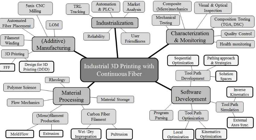
materials and predict the outcome of the production process. The multi-disciplinary
context of the research may be situated through a web of related technologies and
processes, as is shown in figure 1.1. As each of the technologies can easily be the
topic of an in-depth research, the focus of this research is not one of these items
individually, but the interaction of these technologies with the application and the
concepts within these fields that can be used or combined into the new AM process
of printing with continuous fibers.
1.2 Problem Statement
A variety manufacturing methods are currently available to produce quality, high
strength-to-weight components. Continuous fiber composites, such as carbon or
aramid fiber composites, are some of the highest strength to weight material systems
currently available that fit within the financially acceptable limits for their
applica-tions. There are a handful of manufacturing processes available to manufacture these
Figure 1.1: The web of technologies related to industrial 3D Printing with continuous fiber
One of the most common methods of manufacturing composites is highly manual:
hand layup and Vacuum or Pressure Assisted Resin Transfer Molding (RTM, figure
1.2a), where plies of fabric are manually draped over a mold, infused with a resin and
then cured offer a low-cost step into the composite manufacturing world. For
com-plex and highly 3 dimensional parts, these processes and methods may get relatively
expensive, as they require significant man-hours and the potential curing equipment
can become significant. More importantly and more relevant to this research topic,
the shape of the structure that can be produced is limited, as composite structures
require molds and tooling that need to be removable in most cases. Furthermore,
they are mostly suitable for structures that are relatively simple in shape, as highly
complex and 3D parts require tooling that comes at a steep pricetag.
More automated methods of composite manufacturing areAutomated Tape Laying
(ATL) and Automated Fiber Placement (AFP), as shown in figure 1.2b. Both are
similar rapid AM methods that require roller pressure to ensure the placed tape or
(a) (b)
Figure 1.2: Common composite manufacturing methods at the McNAIR Center: (1.2a) VARTM of two skin panels for a UAV and (1.2b) Automated Fiber Placement.
composite material is (quasi-)geodesically wound around a (rotating) mandrel can be
used to manufacture high strength revolution-type objects, however the possible fiber
paths can be quite constrained, depending on the base objects shape. A similar
drawback exists for compositeBraiding, a process that resembles filament winding in
the sense that now a braid, instead of a tape/tow, is overlayed onto a base mold. The
most significant differences with winding are the process speed and fiber path angles.
As with filament winding, for braiding, the mold is embedded in the composite after
curing and, depending on the objects shape, may be very hard or even impossible
to remove. Furthermore, ATL, AFP and filament winding are technologies perfected
to rapidly produce relatively thin shell like structures in the build direction and,
although some stiffener or grid generation is possible through clever path structuring,
they struggle or generally lack the ability to manufacture highly complex non-shell
3D reinforced structures.
Whether one considers hand Layup, AFP, ATL or filament winding, all of these
ex-isting additive manufacturing methods require one or multiple stiff and strong molds
that are machined to tolerances and behave well under autoclave and in- and
post-process pressures to ensure the part maintains it shape. These molds/tools allow the
parts to be produced within acceptable tolerances and quality, however they are the
and lead time on low volume production components. For some components, this may
be a reason not to pursue Additive Manufacturing or composite manufacturing at all,
which limits the engineer’s design freedom. There is thus a desire to expand the scope
of manufacturing processes for mold/tool-less high strength-to-weight composites.
A secondary problem arises from the history and marketing of 3D Printing. 3D
printing has gained a lot of traction as a rapid prototyping method, and is known
to be a relatively young, but promising technology. Although the general consensus
is slowly changing, many professionals and decision makers still consider 3D
print-ing as a gimmick, and do not consider it a worthy option for the manufacturprint-ing of
functional end-user components. An additional research problem is thus, through
design for functionality, to prove the viability and technology readiness for functional
components.
Through continued research, multi-axis continuous fiber reinforced 3D printing
offers the opportunity to reduce manufacturing cost of highly three-dimensional
com-posite structures. It has the potential to reduce non-recurring expenses as it is a
tool-less, mold-less and largely automated process to make functional components.
The ability to print with continuous fiber reinforced plastics can greatly increase the
strength of the component within the layers, however having the anisotropy of a
com-posite material system only enhances the already-inherent anisotropy of 3D printed
components. To insure these printed components do not delaminate or
underper-form, it is important to add reinforcement of the fiber along the build direction of
the base layer in complex 3D parts. Fortunately, with careful design for
modular-ity, FFF systems allow for continuous fiber deposition head to be integrated on a
full 6-axis robotic platform. Continuous fiber reinforced additive manufacturing with
multi-material deposition capabilities have the opportunity to fill this void in
man-ufacturing processes, allowing for true 3D printing of 3D composites for a variety of
1.3 Purpose of the Study
The purpose of this research is to identify a need, and to identify and then tackle the
major scientific challenges in development of printing with continuous fiber printing
and to develop baseline processes that can lead to prototypes and commercialization
in high tech industry. The eventual purpose is to provide industry with a new tool to
add to the inventory of functional manufacturing methods of composite parts while
complying and satisfying aerospace standards that fit the application. As early
adop-tion is desired, the focus of the research is on cabin interior applicaadop-tions, which are
subject to FAR 25[115]. As the technology is in its infancy, the primary focus of
this research is high-performance markets where early adaptation of new technology
is desired in a ”pull to industry”-fashion. Additionally, the technology allows
pro-duction of high strength-to-weight custom shapes, which are desirable in applications
where part mass is important. Examples of this are cutting edge aerospace and
per-formance automotive applications. During the ”hype of 3D printing”-phase in 2012
(figure 1.3), many companies emerged and have since disappeared from the printer
manufacturing platform as they were targeting too broad of a customer base (from
home users to industry giants), or had systems that required 3D printing skills not
available to the consumer at the time of purchase. During the time of this research,
from 2014 to 2017, 3D printing has passed this hype cycle peak, and is currently
go-ing through the ”Trough of Disillusionment”, a dark valley where many investments
remain unreturned [121].
The purpose is thus not to market to a broad base of consumers or high volume
markets but rather focus on few important research & development cases that can
benefit from the technology and will pull in the technology, rather than a broad
marketing campaign. As such, the printer prototypes developed in this research are
not turnkey-systems, but they are modular and modifiable systems to fit an industry
Figure 1.3: Gartner’s 2012 Hype Cycle for Emerging Technologies[121]
The purpose of this study is not to replace the current manufacturing methods
or to combine them with an over-arching process, as existing processes have been
op-timized for decades and their survival proves that they are suitable for their market
segment. It is the author’s hope that this research will provide an additional
manufac-turing tool and method, which fits in its own market (which could partially overlap
other processes’ markets), that can be used to produce integrated highly-tailored
performance composite 3D printed components.
1.4 Hypotheses
Through the course of this research, the following hypotheses were investigated:
1. Continuous fiber 3D Printing fills an interesting void in modern additive
man-ufacturing methods, and allows for rapid manman-ufacturing of new, complex,
2. Fused filament fabrication is the most suitable AM technology to print complex
3D composite materials.
a) The principles of fused filament fabrication can be used to print with
con-tinuous carbon fiber
3. Material formatting within tolerances is essential for the quality of the 3D
printed composites
a) Monofilament variations have a direct correlation to print quality
b) It is possible to manufacture thermoplastic monofilament with sufficient
tolerances at a competitive rate with respect to industry prices
c) An additional preprocessing step is required to the carbon fiber material
to improve interlaminar strength of the product.
d) Impregnation of carbon fiber tows improves product quality and strength.
4. Current Commercially Off-The-Shelf (COTS) software can be modified and
utilized together with in-house developed software to:
a) Define and optimize a toolpath for multi-axis multi-material 3D printing
b) Simulate the generated toolpath and integrate the printing functionality
c) while maintaining compatibility with common NC software
5. A continuous fiber AM process can be developed applicable to the industrial
scale and focused on scalability:
a) Liquefier and feedstock thermodynamics and mechanics play a vital
im-portant role in the process
6. Current testing procedures can be applied to perform elementary mechanical
1.5 Significance of the Study
Although the previous sections already alluded to the significance of this study, it is
important to reflect on the implications of the outcome of this study, and how they
can affect industry and society in general. In section 1.1, the importance of
compet-itiveness was highlighted, and how industries and businesses are constantly pursuing
the state of the art to stay alive and ahead of the market. The findings of this study
and the prototype systems resulting from the research on the topic can have near
direct application in industry, especially in areas where high variability and low
vol-ume production is common, such as the automotive, aerospace and medical fields. A
process and accompanying equipment that allow high customization and variability
for the Out-Of-Autoclave (OOA), distributed production of functional composite 3D
printed parts will be adopted readily as long as the supporting structure and
feed-back is there to improve the technology, and the part size and production volume
allow for this technology. It should be noted that this technology is the start of a
new technological S-curve, where the first iterations of the equipment will still have
significant room for improvement. However, as the equipment, its capabilities and its
support evolve and mature, the cost to industry will reduce and more wide-spread
adaptation is expected to occur.
An example of a potential use and lead time reduction is given for the medical
applications of this technology, i.c. prosthetics or orthotics[57]. Currently, a patient
who requires a prosthetic limb has to undergo several fitting sessions where a
plas-ter cast is made and used to generate a geometrical copy of the limb that receives
the prosthetic. Once the duplicate is made a hand-layup procedure is used to drape
carbon fiber weaves over the cast which then need to be cured at elevated
temper-atures. Once the part has cured, it is test-fitted with the patient, and the iteration
of this mold-making only stops once the use of the prosthetic is within the patient’s
thousands of dollars. The whole process does repeat as the patient ages or gains or
loses weight. An alternative approach of this would be where the limb is scanned
with a 3D scanner, the digital replicate is modified to the desired prosthetic, which
is then 3D printed with continuous fiber, a process that could be a matter of hours
or days instead of weeks or months, saving both valuable time, money and resources
on reduced iterations.
Once industry has access and has well received this technology (which the author
in no way suggests will be quick or easy), design choices will be affected and new, more
variable and pragmatic designs can lead to more optimal manufacturing solutions
which can benefit the general population.
1.6 Research Scope
The over-arching goal of this research is to prove, demonstrate and quantify the
3D printing of continuous carbon fiber with engineering thermoplastics. As such,
the scope of the research entails the printing process, which is dominated by the
process development and optimization required to uniformly produce these parts.
The uniformity of the process can be measured through various quantifiers:
• The success-rate of the prints, a measure of how often a print fails for any
reason.
• The consistency and variability of quality of different prints with the same input
parameters
• The mechanical, optical or other performance metrics of the prints, which are
metrics that can be tested through standardized tests.
In order to improve the uniformity, (either by means of improving the consistency,
reliability and performance of the prints) the uniformity of the inputs of the
printing, or additive manufacturing as a whole, however, thus requires the study to
expand beyond the printing process and quantifying process, to also include the
in-put materials and software development. As none of the properly formatted inin-put
materials were able to be procured from reliable industry sources for reasons further
explained in chapter 3, both the monofilament and carbon fiber filament production
were added to the scope, adding relatable processes such as polymer extrusion and
fiber impregnation. Furthermore, as the toolpath generation software with the
appro-priate requirements was not available commercially off the shelf as further detailed
in chapter 5, the scope was expanded to include the development for the software
with which takes into account all limitations of the current printing process. The
scope of the research can thus be visualized by focusing on the flow of information
and processes, as shown in figure 1.4.
Figure 1.4: The scope of the research spans all pre- and post-processing steps required for quality printing with continuous fibers.
One must note the focal points in this research that will not be addressed
throughly, although hinted on sporadically throughout this dissertation. The
research will, for example, not address the specifics of viscous melt flow in terms of
of impregnation. The research documented in this work is primarily concerning
process development for industrial continuous fiber reinforced printing, and as such
it will not discuss the mechanical modeling, simulation or behavior of the printed
specimen beyond elementary Classical Lamination Theory (CLT) and coupon tensile
testing. Furthermore, this research will not discuss any business-related propositions
or plans concerning the resulting product or equipment, as these are considered
beyond the scope of a doctoral dissertation in engineering.
1.7 Dissertation Outline
The outline of this dissertation follows a logical workflow throughout the processes
of printing with continuous carbon fiber, starting with a state-of-the-art study,
fol-lowed by material requirements and production, the mechanics and toolpathing of
the printing itself, and finally the characterization of the printed products.
A comprehensive state of the art study is reviewed in chapter 2, touching on the
subjects of material formatting, multi-axis Fused Filament Fabrication and toolpath
planning for additive manufacturing. In chapter 3, the need for material formatting is
elaborated, and the requirements and processing steps developed for continuous fiber
printing concerning material formatting on both the monofilament and the continuous
fiber filament are detailed. The intricacies concerning the liquefier and nozzle
geome-try and overall printing process variables required for printing with continuous fiber,
once the material has been formatted, are covered in chapter 4. The two prototype
printers developed to support this research are also described and detailed here. Once
the technology to print has been understood, this knowledge needs to be applied to
the right geometries for 3D printing desired parts. The study of designing,
optimiz-ing, programming and simulating the desired toolpath and its corresponding robot
motion is elaborated on in chapter 5. In chapter 6, the printed parts are subjected
mechanical strength and stiffness, but also parts porosity and consistency. Finally,
a summary of the work together with recommendations for future work or research
Chapter 2
State of the Art & Framework
The state of the art presented in this chapter is based on the division of the web of
technologies related to 3D printing with carbon fiber, as was visualized in figure 1.1.
For the reader to orient himself in the world of 3D printing, a general review of the
current state of the art from the industrial and economic perspective is presented in
section 2.1. In section 2.2, current Additive Manufacturing, in particular 3D printing
technologies and the material systems that these processes allow for, are briefly
re-viewed. A summary of the type of current capabilities of Fused Filament Fabrication
is provided in section 2.3. 3D printing requires a certain format of material for it
to function correctly. The current state of the art of material formatting from the
perspective of 3D printing with continuous fibers is presented in section 2.4. All
com-puter controlled manufacturing equipment, and 3D printers are no exception to this,
require software and instructions to operate and to perform their functions.
There-fore, in section 2.5, a brief review of toolpathing approaches and software, together
with (Computer) Numerically Controlling ((C)NC) software is discussed. Once the
parts have been manufactured, testing and characterization is required to evaluate
their optical, mechanical and compositional properties. The considerations of
char-acterization in the light of 3D printing is presented in section 2.6. Finally, in section
2.7, the over-arching framework on the integration of manufacturing together with
functional 6-axis 3D printing with multiple materials is presented.
This chapter contains content from the author’s published research in proceedings
Aided Design conference and Expo” (CAD-conference), 2016 [31], ”Composite and
Advanced Materials Expo” (CAMX), 2016 [35] and ”The International Academy for
Production Engineering” (CIRP) [189], together with lots of inputs from others.
2.1 Industrialization of 3D Printing
Manufacturing’s multiplier effect is the strongest amongst all sectors. For example,
in the United States, according to the US Bureau of Economic Analysis, $1.33 is the
economic activity generated by $1 of sector GDP [66]. Manufacturing methods can be
categorized as being subtractive, additive or deformative based. Subtractive and
de-formative manufacturing development occurred synchronously with the development
of new CAD tools. This has influenced software developers and led to CAD systems
particularly adapted to subtractive manufacturing. In recent years, additive
manu-facturing is emerging as the answer to complex part manumanu-facturing. This is still far
from being a reality due to numerous challenges faced by rapid prototyping systems
such as topology optimization, design modularity, quality and repeatability to name
a few. At a certain stage, Design for Manufacturing and Assembly guidelines took
over the design principles as the major milestone for design modeling. Unfortunately,
this did not take into account additive manufacturing principles as the concepts of
Design for 3D Printing (D3D) or Design for Additive Manufacturing (DfAM) had not
yet attained sufficient maturity to be implemented and were only recently explored
and defined [132]. However, the current state of the art 3D printing produces parts
which, in many cases, can only carry low loading and are not used widely to produce
high strength, close tolerance parts which modern engineering systems require. 3D
printing is more likely to be used to make prototypes, consumable molds and other
non-production items, although increasingly less rare instances have shown the use
of laser sintering of metallic components for more primary applications, such as a
2.1.1 Broader Impacts
The manufacturing sector requires innovative education and research to continue to
develop. The new body of knowledge will contribute to increase the manufacturing
multiplier effect. Being capable to innovate in additive manufacturing will contribute
to manufacturing competition which could lead to the re-shoring of manufacturing
work to developed countries. One can only imagine the benefits that can emerge
from having appropriate software and manufacturing tools that enable the designer
to achieve optimal structural integrity. Nowadays, the state of the art 3D printing
produces parts which can only carry low loading and are not used widely to produce
high strength, close tolerance parts that modern systems require. 3D printing is more
likely to be used to make prototypes, consumable molds and other non-production
items. Through the methodologies discussed in this research, 3D printing can achieve
a status of printing functionally reinforced complex shapes that actually answers
tough requirements in complex domains such as aeronautic applications.
Additive Manufacturing (AM), in particular through the emersion and
develop-ment of 3D printing, has been rapidly expanding throughout industry and hobby
level manufacturing since its start in the 1980’s. 3D printing and rapid prototyping
techniques allow the designer to prototype ideas and devise products and structures
unconceivable with subtractive manufacturing techniques. Since its recent booming,
AM has become a well-recognized method of manufacturing and over the past decade,
commercial and open source hardware and software have allowed the technology to
steadily become more accessible and realistic for both consumer grade and industrial
grade projects. It is estimated that the industries compound annual growth rate was
33.8% over the last 3 years [176]. Reasons for this recent rapid expansion include
the increase of the ability to produce increasingly more complex parts and the high
2.2 Additive Manufacturing & Integral Design
Additive Manufacturing spans the entire range of manufacturing methods where
ma-terial is added to the part in the process, rather than removed or reshaped. It is an
entirely separate approach to the production of parts, and it should be regarded as
such. It is therefore important to consider how design methodologies are influenced
by this and how this has evolved over time. The subsequent subsections briefly touch
on the evolution of the design process (section 2.2.1), and on the effect of additive
manufacturing on existing design paradigms (section 2.2.2).
2.2.1 The Design Process
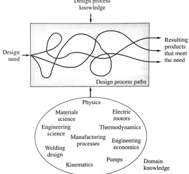
The design process is an intrinsically complex and, without careful optimization
con-straints, can lead to an infinite cycle of product development, as is shown in figure
2.1 from [161, p. 17]. Design iterations can be the result of different processes and
workflows, and as such, the design process is ill-defined and may vary greatly for
different applications. Designs are influenced by the designers preexisting knowledge
and experience, the function(s) of the product, the governing physical, material, or
scientific limitations, and to many design is considered as a black box approach. The
complexity of the design process has increased exponentially in the last centuries,
where, as depicted in figure 2.2 [161, p. 67], early designs had tens of components,
and now common aerospace products can exist of millions of individual parts. As
product quality and fulfillment of design function improved, increase in number of
parts and components followed. Products existing of multiple components require
assembly, and as the number of parts increase, so do the manufacturing and life-cycle
costs, originating from assembly costs, production costs and operational maintenance
costs through the distribution of replacement parts and up to recycling cost. It is thus
in the best interest of the designer to combine as many parts possible into one part
is therefore always desired, but often impractical as subtractive manufacturing has
its limitations towards material variability and processability.
Figure 2.1: Schematic representation of influences to the design process [161, p. 17].
Figure 2.2: An exponential increase in the number of parts shows the need for integral manufacturing to reduce assem-bly costs [161, p. 67].
2.2.2 Additive Manufacturing in Design
Design is a complex, iterative, trial and error based process. The problem is often
ill defined and designers are rarely sufficiently engaged with the people responsible
for other life-cycle phases, such as Manufacturing, Operation, Support, End of Life,
to generate a truly optimal design. Although several methods and techniques are
available and widely applied to support the design process, some of which will be
discussed later, design remains predominantly, in application, an intuitive, iterative,
and partially subjective process which aims for convergence towards a final solution.
Computer Aided Manufacturing had its beginnings in parallel with the development of
numerically controlled subtractive manufacturing processes. Sketchpad, [148], often
referred to as the first CAD system, belongs to the same era as Pronto (as developed
by Patrick J. Hanratty in 1957 [97]), labeled as one of the first Numerical Control
![Fig ur e 1 .3 : G a r t ne r ’s 2 0 1 2Hy pe C y c le f o r E me r g ingT e c hno lo g ie s [1 2 1 ]](https://thumb-us.123doks.com/thumbv2/123dok_us/8373877.1384190/36.612.117.495.72.316/fig-g-ne-hy-ingt-hno-lo-ie.webp)
![Fig ur e 2 .3 : Sk e t c hpa d [1 4 8 ].](https://thumb-us.123doks.com/thumbv2/123dok_us/8373877.1384190/48.612.198.414.411.579/fig-ur-e-sk-e-t-c-hpa.webp)
![Fig ur e 2 .4 : D iff e r e nt v a r ia t io ns o f 3 Dpr int ing , a da pt e d f r o m [1 7 7 ], o r ig ina lly[7 7 ].](https://thumb-us.123doks.com/thumbv2/123dok_us/8373877.1384190/50.612.102.511.172.364/fig-i-io-dpr-int-ing-ina-lly.webp)
![Fig ur e2 .5 : T e ns iles t r e ng t h o f v a r io us3 Dpr int ingpr o c e s s e s[1 7 7 ], a da pt e d f r o m[1 5 4 ].](https://thumb-us.123doks.com/thumbv2/123dok_us/8373877.1384190/51.612.126.507.510.664/fig-t-iles-dpr-int-ingpr-da-pt.webp)
![Fig ur e 2 .7 : C la s s ific a t io n o f T he r mo pla s t ic s [9 1 ]](https://thumb-us.123doks.com/thumbv2/123dok_us/8373877.1384190/54.612.114.502.74.287/fig-c-la-ic-io-he-pla-ic.webp)