Capacity Performance of Wireless OAM-Based Massive
MIMO System
Fuchun Mao1, Ming Huang1, *, Jingjing Yang1, Chengfu Yang1, Tinghua Li2, and Jialin Zhang3
Abstract—Orbital angular momentum (OAM) as a powerful candidate to enhance the spectral efficiency and system capacity by providing the new degree of freedom for multiplexing has been recently advocated in wireless communications. In this paper, we propose an OAM-based massive multiple-input multiple-output (MIMO) scheme to significantly improve the transmission performance of wireless communication system in line-of-sight scene. The uniform rectangular arrays (URAs) are used as transceivers in our system model, and the ideal OAM antenna model that is capable of providing OAM-channel independently is used as the array element. Multiple reference coordinate systems based on per transmitting antenna and the cumulative phase of specific radio vortices are used to describe the OAM-MIMO channel model. The results of numerical analysis indicate that the proposed OAM-based massive MIMO system could obtain an overwhelming capacity gain against the conventional MIMO system.
1. INTRODUCTION
The orbital angular momentum (OAM) of electromagnetic fields characterized by the spiral phase factor of exp(jlϕ) is considered a new degree of freedom for multiplexing, where l and ϕ represent the mode number of OAM waves and the azimuth, respectively [1, 2]. This is of great significance to the telecommunications industry as indicated in Fig. 1, which describes only six degrees of freedom for multiple access, namely the time, frequency, code sequence, space, polarization, and OAM state. They have been deeply developed and utilized at present, except for the OAM state. Hopefully, several validated experimental reports are available in optics [3], millimeter wave [4, 5], and radio frequency [6– 9]. Due to good collimation, OAM-based communication performs much better in optical and millimeter bands than in the radio frequency. What is worse, some initial reports suggest that OAM is just a subset of MIMO technology and does not give any additional capacity gain [10, 11]. The reason for this conclusion is that the presented uniform circular array (UCA) is treated as an OAM generator that only produces a single OAM channel during a time slot. Thus the argued capacity limit of UCA system is indeed the production limit of OAM carriers. Recent researches show more positive results about OAM increasing the channel capacity [12, 13].
As the basis for performance analysis, the channel matrix of wireless OAM-MIMO systems with various array configurations has been studied, such as the typical UCA system [14, 15], misalignment UCA system [16], nested UCA system [17], fractal UCA system [18], and uniform line array (ULA) systems [19, 20]. In spite of offering some inspirations, these reports do not use reference coordinates in analysis process, which is actually of significance due to the extreme spatial coordinate dependence
Received 7 March 2019, Accepted 23 June 2019, Scheduled 2 July 2019
* Corresponding author: Ming Huang ([email protected]).
Figure 1. The map of resource lattice for multiplexing. Heref,t,w,s, andlrepresent frequency-, time-, code-time-, space-time-, and OAM-channel in turn;R and L are right-hand and left-hand circular polarization, respectively.
of OAM fields. In addition, the use of non-OAM antenna model as array element causes some of the above reports to fail to observe the expected capacity gain.
In this paper, we consider an OAM-based massive MIMO system for the line-of-sight wireless communications, in which both the transmitter and receiver consist of a URA. An ideal OAM antenna that is capable of generating OAM wave is used as the transmit-receive antenna in URAs. The relevant wireless channel model is deduced theoretically. Then, the capacity performance of the proposed OAM-based massive MIMO system is performed. The numerical simulation shows some exciting results.
2. SYSTEM MODEL
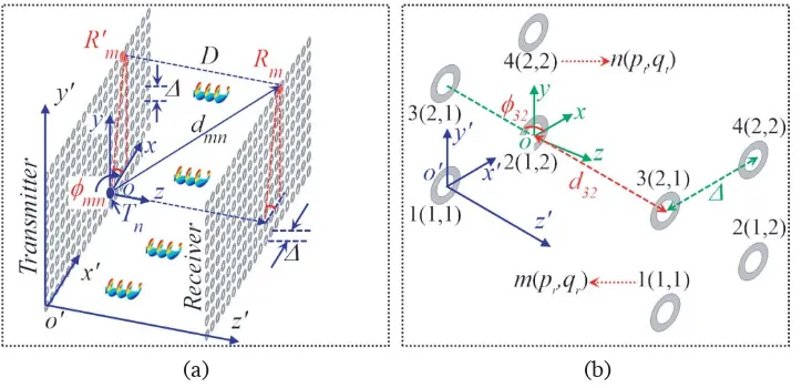
The proposed OAM-based massive MIMO system is shown in Fig. 2(a), whereD is the space between transmitter and receiver; Δ is the space among adjacent elements in URAs;dmndenotes the propagation
distance from then-th transmitting antenna Tn to them-th receiving antenna Rm; andφmn represents
the initial azimuth ofRmreferencing toTn. Rmis the normal projection ofRm. As depicted in Fig. 2(b),
we code the antennas with n(pt, qt) in the transmitter and m(pr, qr) in receiver for the convenience of
(a) (b)
subsequent analysis. Here pt and pr denote the serial number of rows in the URAs, while qt and qr
represent the serial number of columns, respectively. In addition, o-xyz is the original coordinate system for the whole system, whileo-xyzis the reference coordinate system of Tn. The transformation
relationship between them is given below
x=x−(qt−1)Δ, y=y−(pt−1)Δ, z=z (1)
The reason for applying the reference coordinates is the intrinsic spatial dependence of OAM fields. The azimuthal angle ϕ in spiral phase factor exp(jlϕ) has to be the angular coordinate around the beam-axis of OAM waves. In other words,ϕ has to be defined by o-xyz rather than o-xyz. In such an OAM-based massive MIMO system, the received signals can be expressed as
Y=HX+n (2)
Here Y = [y1,· · ·, yi,· · · , yM]T is the received signal vector, in which yi =
N
j hijx˜j +ni is the
signals and noise obtained by thei-th receiving antenna. X= [˜x1,· · ·,x˜i,· · · ,x˜N]T is the transmitted
signals with ˜xj = [l1,· · · , lk,· · ·, lQ]T denoting the OAM signals modulated by the j-th transmitting
antenna, wherelk is the channel label of certain OAM signal. n= [n1,· · ·, ni,· · ·, nM]T is the complex
Gauss white noise vector introduced by the wireless link. H = [h1,· · · ,hj,· · · ,hN]T is the channel matrix withhj representing the channel response vector between thej-th transmitting antenna and all receiving antennas. When the channel state information (CSI) of the system is known, an optimal power allocation will be applied at the transmitter. According to the Shannon’s channel capacity theorem, the capacity of the proposed OAM-based massive MIMO system can be expressed as
C =
γ
j
log2
1 + Pj σ2/δ2
j
bps/Hz (3)
Hereγ and δj are the rank and singular value of channel matrix, respectively. σ is the variance of
noise. pj is the sub-power allocated by the water-filling principle.
3. CHANNEL MODEL
The transfer function fromTntoRmcan be considered as the MIMO response superimposed by a spiral
phase term [14], and expressed as follows
hmn=hmimomn ·hoammn =
λβ 4πdmne
−j2π
λdmn·ej˜lnϕ˜mn,l (4)
Here β is a constant containing attenuation and phase caused by antennas and their patterns on both sides [10];λdenotes the wavelength; ˜ln=l1, . . . , lQ contains all OAM fields generated byTn; and
˜
ϕmn,l denotes the cumulative phases of the l-labeled OAM carrier after propagating from Tn to Rm.
The channel matrix of the proposed OAM-based massive MIMO system is completely determined by Eq. (4), in which onlydmn and ˜ϕmn,l are pending. According to Fig. 2(a), the propagation distance
dmn can be calculated by
dmn= sqrt
D2+ [(pt−pr)×Δ]2+ [(qt−qr)×Δ]2
(5) and the cumulative phases ˜ϕmn,l can be performed by
˜
ϕmn,l =φmn+ 2π·˜ln·Dλ (6)
equal for all ˜ln OAM carriers. It can be calculated by
φmn =
⎧ ⎪ ⎪ ⎪ ⎪ ⎪ ⎪ ⎪ ⎪ ⎪ ⎪ ⎪ ⎨ ⎪ ⎪ ⎪ ⎪ ⎪ ⎪ ⎪ ⎪ ⎪ ⎪ ⎪ ⎩
arctan (|pt−pr|/|qt−qr|), pr> pt, qr > qt
π−arctan (|pt−pr|/|qt−qr|), pr> pt, qr < qt
π+ arctan (|pt−pr|/|qt−qr|), pr< pt, qr < qt
2π−arctan (|pt−pr|/|qt−qr|), pr< pt, qr > qt
0, pr=pt, qr ≥qt
π/2, pr> pt, qr =qt
π, pr=pt, qr < qt
3π/2, pr< pt, qr =qt
(7)
In order to simplify the formulas without loss the generality, we consider the simple case of each transmitting antenna generating only a single OAM carrier, and the topological charge of the generated radio OAM carrier equals its own serial number, namely ˜ln=n.
4. CAPACITY ANALYSIS AND SIMULATION
4.1. Conventional MIMO System
To show more details about the capacity analysis on the proposed OAM-based massive MIMO system, we begin with a 4×4 URA based system as depicted in Fig. 2(b). The matrix of propagation distance can be obtained by using Eq. (5) below
d=
⎡ ⎢ ⎢ ⎣
d11 d12 d13 d14 d21 d22 d23 d24 d31 d32 d33 d34 d41 d42 d43 d44
⎤ ⎥ ⎥ ⎦= ⎡ ⎢ ⎢ ⎣
D d1 d1 d2 d1 D d2 d1 d1 d2 D d1 d2 d1 d1 D
⎤ ⎥ ⎥
⎦ (8)
where d1 = (D2+ Δ2)1/2, andd2 = (D2+ 2Δ2)1/2. The symmetry of d may be useful in reducing the computational complexity. Substituting Eq. (8) into Eq. (4) and making hoammn = 1, the channel matrix for conventional MIMO system can be written as
Hmimo = λβ 4π ⎡ ⎢ ⎢ ⎢ ⎢ ⎣
e−jkD/D e−jkd1/d1 e−jkd1/d1 e−jkd2/d2 e−jkd1/d1 e−jkD/D e−jkd2/d2 e−jkd1/d1 e−jkd1/d1 e−jkd2/d2 e−jkD/D e−jkd1/d1 e−jkd2/d2 e−jkd1/d1 e−jkd1/d1 e−jkD/D
⎤ ⎥ ⎥ ⎥ ⎥
⎦. (9)
wherek= 2π/λ.
4.2. OAM-Based MIMO System
The channel matrix of the 4×4 URAs-based OAM-MIMO system is obtained by applying Eq. (4) as
H= βλ 4π ⎡ ⎢ ⎢ ⎢ ⎢ ⎢ ⎢ ⎢ ⎢ ⎢ ⎢ ⎢ ⎢ ⎣
e−jkD−jϕ11 D
e−jkd1−j2ϕ12 d1
e−jkd1−j3ϕ13 d1
e−jkd2−j4ϕ14 d2
e−jkd1−jϕ21
d1
e−jkD−j2ϕ22 D
e−jkd2−j3ϕ23 d2
e−jkd1−j4ϕ24 d1 e−jkd1−jϕ31
d1
e−jkd2−j2ϕ32 d2
e−jkD−j3ϕ33 D
e−jkd1−j4ϕ34 d1 e−jkd2−jϕ41
d2
e−jkd1−j2ϕ42 d1
e−jkd1−j3ϕ43 d1
whereϕmn is ruled by Eq. (6) with ˜ln=n. According to Eq. (7) and Fig. 2(b), the initial phase matrix
φis obtained as
φ=
⎡ ⎢ ⎢ ⎣
φ11 φ12 φ13 φ14 φ21 φ22 φ23 φ24 φ31 φ32 φ33 φ34 φ41 φ42 φ43 φ44
⎤ ⎥ ⎥ ⎦= ⎡ ⎢ ⎢ ⎣
0 π 3π/2 5π/4 0 0 7π/4 3π/2 π/2 3π/4 0 π π/4 π/2 0 0
⎤ ⎥ ⎥
⎦ (11)
Substituting Eq. (11) and Eq. (6) into Eq. (10), the channel matrix for the 4×4 URAs based OAM-MIMO system can be obtained as
H= βλ 4π ⎡ ⎢ ⎢ ⎢ ⎢ ⎢ ⎢ ⎢ ⎢ ⎢ ⎢ ⎢ ⎢ ⎣ 1 D
e−jk(d1−4D) d1
je−jk(d1−9D) d1
−e−jk(d2−16D) d2 e−jk(d1−D)
d1
ej3kD D
e−jk(d2−9D)ej21π/4 d2
e−jk(d1−16D) d1 je−jk(d1−D)
d1
−je−jk(d2−4D) d2
ej8kD D
e−jk(d1−16D) d1 e−jk(d2−D)·ejπ/4
d2
−e−jk(d1−4D) d1
e−jk(d1−9D) d1
ej15kD D ⎤ ⎥ ⎥ ⎥ ⎥ ⎥ ⎥ ⎥ ⎥ ⎥ ⎥ ⎥ ⎥ ⎦ (12)
4.3. Simulation Results
In this section, both the conventional massive MIMO and OAM-based massive MIMO are discussed in wireless line-of-sight scenario. To observe the capacity performance of the simplified 4×4 URAs based system, the main simulation parameters are set as below: the carrier frequency and corresponding carrier wavelength are 66 GHz and 4.55 mm, respectively; the gain coefficientβ equals 40 dB; the transmitting power is 1 W; the signal-noise-rates (SNR) are 10 dB and 30 dB, respectively; the space among adjacent elements Δ takes 20λ. The OAM state of transmitting antennas is set by ˜ln=n, namely, the 1st, 2nd,
3rd, and 4th transmitting antennas radiate the OAM carriers with the topological charge of 1, 2, 3, and 4 in order.
Figure 3(a) depicts the capacity performance of the 4×4 URAs based conventional MIMO system and OAM-MIMO system, with the space between transmitter and receiver D varying from 100λ to 20000λ. Obviously, the OAM-MIMO system shows a better capacity performance than the conventional MIMO system. For instance, at the propagation distance of D = 10310λ, the OAM-MIMO system
(a) (b)
obtains a channel capacity of 25.82 bps/Hz and 7.744 bps/Hz corresponding to SNR = 30 dB and SNR = 10 dB, respectively. The conventional MIMO system’s channel capacities are 7.455 bps/Hz and 0.9715 bps/Hz with the same setting, which are only 28.87% and 12.55% of the OAM-MIMO system, respectively. Fig. 3(b) shows the capacity performances of the two systems over an SNR region of −10 dB ∼ 30 dB, with the propagation distances taking 2000λ and 20000λ, respectively. We can draw the conclusion that is consistent with Fig. 3(a). Taking SNR = 20 dB as an example, we can see from Fig. 3(b) that the conventional MIMO obtains a channel capacity of 1.765 bps/Hz atD= 20000λ and 18.15 bps/Hz at D = 2000λ, while the channel capacity of the OAM-MIMO is 11.82 bps/Hz and 25.91 bps/Hz at the same setting. The OAM-MIMO performs 6.7 times and 1.43 times better than the conventional MIMO, respectively. This infers that the conventional MIMO is capable of promoting multiplicative capacity gain by joining the OAM techniques, and the capacity gain increases significantly with the increase of propagation distance and the decrease of SNR.
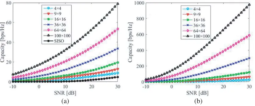
According to the theory of the massive MIMO system, no matter the conventional case or the OAM based case, the capacity performance will be enhanced significantly with the used transmitting-receiving elements increasing. This is revealed by Fig. 4, in which the propagation distance is 5000λ; the space among adjacent elements is 5λ; then-th transmitting antenna radiates then-labeled OAM carrier; and the used antennas are 4×4, 9×9, 16×16, 32×32, 64×64, 100×100 in order. The transmitting power is 1 W. Taking SNR = 30 dB into account, the channel capacities with the used elements ascending are 8.737, 12.85, 19.6, 33.65, 53.48, 78.86 (bps/Hz) for the conventional massive MIMO systems, and 24.58, 61.97, 119, 299.1, 587.5, 973.8 (bps/Hz) for the proposed OAM-based massive MIMO systems, and 4.719 (bps/Hz) for the single-input single-output (SISO) system. Therefore, the OAM-based massive MIMO is orderly more excellent than the conventional massive MIMO 2.813 times, 4.823 times, 6.072 times, 8.89 times, 10.99 times, and 12.35 times, and much more overwhelming than SISO system.
(a) (b)
Figure 4. The capacity performance of: (a) conventional massive MIMO system and SISO system; (b) the proposed OAM-based massive MIMO system.
5. CONCLUSIONS
ACKNOWLEDGMENT
This work was supported by the National Natural Science Foundation of China (Grant Nos. 61461052, 61863035, 11564044), the Seventh of Yunnan University Graduate Student Scientific Research Project (Grant No. ynuy201443), and the doctoral award for the academic newcomers (2014) of Yunnan Province.
REFERENCES
1. Djordjevic, I. B., “Multidimensional OAM-based secure high-speed wireless communications,”
IEEE Access, Vol. 5, 16416–16428, 2017.
2. Mao, F. C., M. Huang, C. F. Yang, T. H. Li, J. L. Zhang, and S. Y. Chen, “Orbital angular momentum generation using circular ring resonators in radio frequency,” Chinese Phys. Lett., Vol. 35, No. 2, 020701, 2018.
3. Ren, Y. X., Z. Wang, P. C. Liao, L. Li, G. D. Xie, H. Huang, Z. Zhao, Y. Yan, N. Ahmed, A. Willner, M. P. J. Lavery, N. Ashrafi, S. Ashrafi, R. Bock, M. Tur, I. B. Djordjevic, M. A. Neifeld, and A. E. Willner, “Experimental characterization of a 400 Gbit/s orbital angular momentum multiplexed free-space optical link over 120 m,”Opt. Lett., Vol. 41, No. 3, 622–625, 2016.
4. Yan, Y., G. D. Xie, M. P. J. Lavery, H. Huang, N. Ahmed, C. J. Bao, Y. X. Ren, Y. W. Gao, L. Li, Z. Zhao, A. F. Molisch, M. Tur, M. J. Padgett, and A. E. Willner, “High-capacity millimeter-wave communications with orbital angular momentum multiplexing,”Nat. Commun., Vol. 5, 4876, 2014. 5. Shi, Y. and Y. Zhang, “Generation of wideband tunable orbital angular momentum vortex waves
using graphene metamaterial reflectarray,” IEEE Access, Vol. 6, 5341–5347, 2018.
6. Tamburini, F., E. Mari, G. Parisi, F. Spinello, M. Oldoni, R. A. Ravanelli, P. Coassini, C. G. Someda, B. Thid´e, and F. Romanato, “Tripling the capacity of a point-to-point radio link by using electromagnetic vortices,” Radio Sci., Vol. 50, No. 6, 501–508, 2015.
7. Yu, S. X., L. Li, G. M. Shi, C. Zhu, and Y. Shi, “Generating multiple orbital angular momentum vortex beams using a metasurface in radio frequency domain,” Appl. Phys. Lett., Vol. 108, No. 24, 241901, 2016.
8. Mao, F., M. Huang, T. Li, J. Zhang, and C. Yang, “Broadband generation of orbital angular momentum carrying beams in RF regimes,” Progress In Electromagnetics Research, Vol. 160, 19– 27, 2017.
9. Yu, S. X., L. Li, G. M. Shi, C. Zhu, X. X. Zhou, and Y. Shi, “Design, fabrication, and measurement of reflective metasurface for orbital angular momentum vortex wave in radio frequency domain,”
Appl. Phys. Lett., Vol. 108, No. 12, 121903, 2016.
10. Edfors, O. and A. J. Johansson, “Is orbital angular momentum (OAM) based radio communication an unexploited area?,”IEEE Trans. Antenn. Propag., Vol. 60, No. 2, 1126–1131, 2012.
11. Cagliero, A. and R. Gaffoglio, “On the spectral efficiency limits of an OAM-based multiplexing scheme,” IEEE Antenn. Wirel. Pr., Vol. 16, 900–903, 2016.
12. Cheng, W. C., H. L. Zhang, L. P. Liang, H. Y. Jing, and Z. Li, “Orbital-angular-momentum embedded massive MIMO: Achieving multiplicative spectrum-efficiency for mmWave communications,”IEEE Access, Vol. 6, 2732–2745, 2017.
13. Zheng, S. L., R. F. Dong, Z. F. Zhang, X. B. Yu, X. F. Jin, H. Chi, Z. N. Chen, and X. M. Zhang, “Non-line-of-sight channel performance of plane spiral orbital angular momentum MIMO systems,”
IEEE Access, Vol. 5, 25377, 2017.
14. Zhu, Q. B., T. Jiang, D. M. Qu, D. Chen, and N. R. Zhou, “Radio vortex input multiple-output communication systems with high capacity,” IEEE Access, Vol. 3, 2456, 2015.
15. Lei, W., F. Jiang, Z. Yuan, J. Yang, G. Gui, and H. Sari, “Mode division multiple access: A new scheme based on orbital angular momentum in millimeter wave communications for fifth generation,” IET Commun., Vol. 12, No. 12, 1416–1421, 2018.
17. Opare, K., Y. Kuang, and J. Kponyo, “Mode combination in an ideal wireless OAM-MIMO multiplexing system,”IEEE Wirel. Commun. Lett., Vol. 4, No. 4, 449–452, 2015.
18. Zhao, L. J., H. L. Zhang, and W. C. Cheng, “Fractal uniform circular arrays based multi-orbital-angular-momentum-mode multiplexing vortex radio MIMO,” China Commun., Vol. 15, No. 9, 126–143, 2018.
19. Wang, L., X. H. Ge, R. Zi, and C. X. Wang, “Capacity analysis of orbital angular momentum wireless channels,” IEEE Access, Vol. 5, 23069–23077, 2017.