Parametric Study of RMSA for WLAN and
Wi-Max Applications
Jagadevi Gudda*1, Dinesh B Ganure 2, P M Hadalgi 3
Research Scholar, Department of Applied Electronics, Gulbarga University, Kalaburagi, Karnataka, India1
Research Scholar, Department of Applied Electronics, Gulbarga University, Kalaburagi , Karnataka, India2
Professor, Department of Applied Electronics, Gulbarga University, Kalaburagi, Karnataka, India3
ABSTRACT: The objective of this paper is to study the effect of pentagon slot on the antennas characteristics like return loss and impedance bandwidth. For this purpose a simple rectangular micro strip antenna (RMSA) is considered for ease of analysis. To start with, first a RMSA is designed and then it is modified by etching pentagon slot at various locations of the patch to study effect of it on antennas parameters.
KEYWORDS: Pentagon slot, return loss, impedance bandwidth, Rectangular Microstrip Antenna.
I.INTRODUCTION
Physically, MSA consists of a metallic radiating patch backed up by a dielectric substrate and a ground plane below that. These days, MSAs are widely used in many applications due to their inherent advantages such as low profile, lightweight, planer configuration and ease of fabrication. However, main limitation of MSAs is their inherently narrow bandwidth [1]. Microstrip patch antenna can be used for multiband operation and it can be achieved by cutting various slots on the radiating patch and ground [2-4]. Optimization of the design and efficiency of printed antennas are used in communication systems [5-8]. Norbahiah Misran [2] has proposed a multi-slotted microstrip patch antenna for wireless communication system. A comparative analysis of the various geometries of MSA obtained by inserting slots on the radiating patch indicate considerable improvement in performance parameters of MSA such as return loss, radiation pattern and gain is found to be rare in the literature.
II.ANTENNA DESIGN
The proposed antenna is designed using a low cast glass epoxy substrate material of area X x Y having a thickness h = 0.16 cm with dielectric constant εr = 4.2. The artwork of this antenna is sketched using computer software AutoCAD to achieve better accuracy.
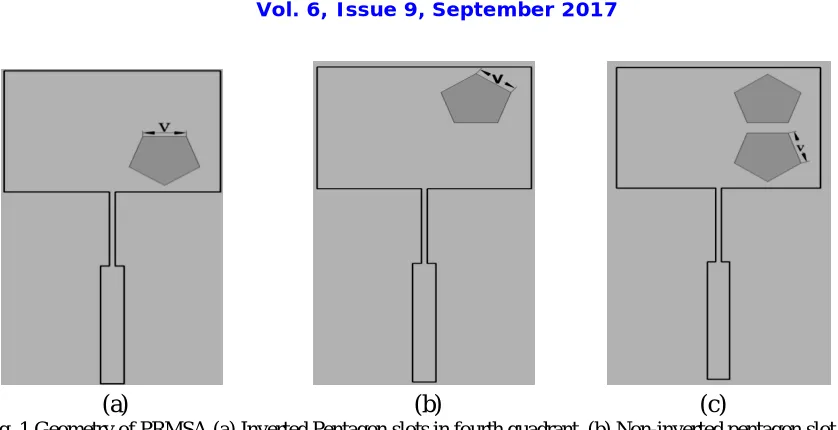
Figure 1 (a) to (c) shows the top view geometry of the pentagon slot loaded rectangular microstrip antenna (PRMSA). The PRMSA is designed for 3.2 GHz of frequency of conventional rectangular microstrip antenna (CRMSA).
The antenna consists of a radiating patch of length L and width W. The antenna is excited through a simple microstrip line feed of length Lf and width Wf . A 50Ω semi miniature connector is used to feed the microwave power. The quarter wavelength transformer of length Lt and width Wt is used to match the impedance between Cp and microstrip line feed.
ISSN (Print) : 2320 – 3765 ISSN (Online): 2278 – 8875
I
nternational
J
ournal of
A
dvanced
R
esearch in
E
lectrical,
E
lectronics and
I
nstrumentation
E
ngineering
(A High Impact Factor, Monthly, Peer Reviewed Journal)
Website: www.ijareeie.com
Vol. 6, Issue 9, September 2017
(a)
(b) (c)
Fig. 1 Geometry of PRMSA (a) Inverted Pentagon slots in fourth quadrant, (b) Non-inverted pentagon slot in first quadrant and (c) Inverted and non inverted slots in fourth and first quadrant.
The design parameters of the proposed antenna are given in Table 1.
Table 1 Design parameters of PSRMA
Antenna Parameters L W Lf Wf Lt Wt V
Dimensions in cm 2.24 2.91 2.183 0.317 1.372 0.078 0.58
III. EXPERIMENTAL RESULTS AND DISCUSSION
The simulation of the proposed antenna is carried out by using Ansoft electromagnetic 3D-tool. The antenna bandwidth over return loss less than -10 dB is measured experimentally by using Vector Network Analyzer (Rohde & Schwarz, Germany make ZVK model 1127.8651). The experimental bandwidth is calculated by using the formula,
BW= (fH – fL/ fr)*100% ... ( 1 )
where fH and fL are upper and lower cut off frequencies respectively, when its return loss reaches 10 dB and fr is the resonance
frequency between fH and fL.
Fig. 3 Variation of frequency versus return loss of PRMSA with slot in first quadrant
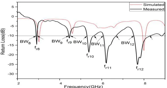
Fig. 4 Variation of frequency versus return loss of PRMSA with slot in first and fourth quadrant
The variation of return loss versus frequency of PRMSA when inverted pentagon slot is loaded in the fourth quadrant of rectangular patch is as shown in Figure 2. From this figure it is observed that, the antenna operates for triple frequency bands BW1 (3.06 – 2.93 GHz) = 4.33%, BW2 (4.61 – 4.47 GHz) = 3.07% and BW3 (8 – 7.89 GHz) = 1.38% for the resonating frequencies of fr1, fr2 and fr3 respectively. These frequency bands are due to independent resonance of the patch and pentagon slot on the radiating patch. The BW1 is considered as primary band because its resonating frequency fr1 is close to fr (2.98 GHz) of CRMSA. The BW2 is considered as secondary band and BW3 as third band respectively. Further, it is seen from Figure 2 that, the simulated result of PRMSA is also shown, which is in good agreement with experimental result.
ISSN (Print) : 2320 – 3765 ISSN (Online): 2278 – 8875
I
nternational
J
ournal of
A
dvanced
R
esearch in
E
lectrical,
E
lectronics and
I
nstrumentation
E
ngineering
(A High Impact Factor, Monthly, Peer Reviewed Journal)
Website: www.ijareeie.com
Vol. 6, Issue 9, September 2017
Figure 4 shows the variation of return loss versus frequency of PRMSA when non inverted and inverted pentagon slots are loaded in the first and fourth quadrant of rectangular patch respectively. From this figure it is observed that the antenna operates for five frequency bands BW8 (2.94 – 2.88 GHz) = 2.05%, BW9 (4.47 – 4.42 GHz) = 1.12%, BW10 (5.64 – 5.29 GHz) = 6.51%, BW11 (6.68 - 6.06 GHz) = 9.98% and BW12 (8.30 – 7.52 GHz) = 10.14% for the resonating frequencies of fr8, fr9, fr10, fr11 and fr12 respectively. Again, it is observed from this figure that the change in construction of PRMSA does not affect much the resonant frequencies fr1 and fr2 of Figure 2 but introduces two additional resonant frequencies fr10 and fr11 in between resonant frequencies fr9 and fr12. Further, it is clear from Figure 4 that, the simulated result of PRMSA is in good agreement with experimental result.
The gain of PRMSA is calculated using absolute gain method given by the formula [9],
( )
=
−
(
)
−
………(2)
where, Gt is the gain of the pyramidal horn antenna and R is the distance between the transmitted antenna and the antenna under test (AUT). The power received by AUT, “Pr”, and the power transmitted by standard pyramidal horn antenna “Pt” are measured independently. The gain measured for PRMSA is found to be 5.59 dB.
Hence by placing the pentagon slot in first, fourth and both in first & fourth quadrants of the rectangular patch the antenna is made to operate for triple, quad and penta bands.
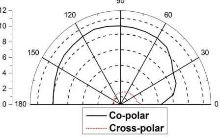
Fig. 5 (a) Radiation pattern at 3 GHz with slot in fourth quadrant
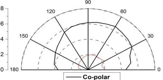
Fig. 5 (c) Radiation pattern at 2.92 GHz with slot in first and fourth quadrant
Figure 5(a) to (c) shows cross-polar and co-polar radiation patterns of PRMSA at 3 GHz, 2.85 GHz and 2.92 GHz. From the figures it is seen that radiation patterns are broadside and linearly polarized [10].
IV.CONCLUSION
A novel design of proposed antenna is realized by CRMSA which is capable of operating for triple, quad and penta bands between 2.85 GHz to 7.95 GHz without change in linearly polarized radiation characteristics. The proposed antennas use low quality substrate material and easy to fabricate. The antenna with slots in first and fourth quadrants shows improved impedance bandwidth compared to single pentagonal slot in first and fourth quadrant separately. This antenna may find application in WLAN, Wi-MAX and fourth generation mobile communication system.
REFERENCES
[1]. Zhi Ning Chen, “Antennas for Portable Devices”, John Wiley & Sons Ltd, 2007.
[2]. Norbahiah Misran, Mohammad Tariqul Islam, Mohammed Nazmus Shakib and Baharudin Yatim, “Design of Broadband Multi-Slotted Microstrip Patch Antenna for Wireless System”, Proceedings of International Conference on Microwave-08, pp. 23 – 25, 2008.
[3]. S. Bhunia, D. Sarkar, S. Biswas, P. P. Sarkar, B. Gupta and K. Yasumoto, “Reduced Size Small Dual and Multi-Frequency Microstrip Antenna” Microwave & optical Technology Letters. Vol. 50, No.4, pp. 961 – 965, 2008.
[4]. S. Bhunia, M. K. Pain, S. Biswas, D. Sarkar, P. P. Sarkar, and B. Gupta, “Investigations on Microstrip Patch Antennas with Different slots and Feeding Points”, Microwave and Optical Technology Letters, Vol. 50, No. 11, pp. 2754 – 2758, 2008.
[5]. I. Sarkar, P. P. Sarkar and S. K. Chowdhury, “A new compact printed antenna for mobile communication”, IEEE Antennas & Propagation Conference (LAPC 2009) Loughborough University, pp. 109 – 112, 2009.
[6]. Mahmoud N., Mahmoud and Reyhan Baktur, “A Dual Band Microstrip Fed Slot Antenna”, IEEE Transaction on Antennas and Propagation, Vol. 59, No. 5, pp. 1720 – 1724, 2011.
[7]. Wen-Chung Liu, Chao-Ming Wu and Yang Dai, “Design of Triple Frequency Microstrip Fed Monopole Antenna Using Defected Ground Structure”, IEEE Transaction on Antennas and Propagation, Vol. 59, No. 7, pp. 2457 – 2463, 2011.
[8]. YahyaEntiefa Mansour, Single slot dual band microstrip antenna for WiMAX application, Atilim University, June 2014.
[9]. Dinesh B Ganure, S. L. Mallikarjun, P. M. Hadalgi, and P. V. Hunagund, “Proximity coupled rectangular microstrip patch antenna for S-band applications”, International Journal of Research in Engineering and Technology, Vol. 4, No. 5, pp.124-126, 2015.