Doubly Fed Induction Generator Based Wind Energy
Conversion System under Two Phase Voltage Dips
MAHMAD MAZAHARUDDIN 1, D. SIREESHA REDDY2
1PG Scholar, Dept of EEE (EPS), Brilliant Group of Technical Institutions. Hyderabad, TS, India. 2Assistant Professor, Dept of EEE, Brilliant Group of Technical Institutions. Hyderabad, TS, India.
ABSTRACT
The main of this project is operation of doubly fed induction generator (DFIG) with an integrated active filter capabilities using grid-side converter (GSC). In this system DFIG, the reactive power for the induction machine has been supplied from the RSC and the load reactive power has been supplied from the GSC. The decoupled control of both active and reactive powers has been achieved by RSC control. The proposed DFIG has also been verified at wind turbine stalling condition for compensating harmonics and reactive power of local loads. The main contribution of this work lies in the control of GSC for supplying harmonics in addition to its slip power transfer.
In extension the application of a dynamic
voltage restorer (DVR) connected to a
wind-turbine-driven
doubly
fed
induction
generator (DFIG) is investigated. The setup
allows the wind turbine system an
uninterruptible fault ride-through of voltage
dips. The DVR can compensate the faulty
line voltage, while the DFIG wind turbine
can continue its nominal operation as
demanded in actual grid codes
.Index Terms :
Grid side converter(GSC), rotor side converter (RSC), static synchronous compensator (STATCOM)doubly fed induction generator (DFIG), integrated active filter, nonlinear load, power quality, wind energy conversion system (WECS). STATCOMI.INTRODUCTION
conversion system (WECS) to grid disturbance is compared to the fixed speed WECS in [13].
As the wind penetration in the grid becomes significant, the use of variable speed WECS for supplementary jobs such as power smoothening and harmonic mitigation are compulsory in addition to its power generation. This power smoothening is achieved by including super magnetic energy storage systems as proposed in [14]. The other auxiliary services such as reactive power requirement and transient stability limit are achieved by including static compensator (STATCOM) in [15]. A distribution STATCOM (DSTATCOM) coupled with fly-wheel energy storage system is used at the wind farm for mitigating harmonics and frequency disturbances [16]. However, the authors have used two more extra converters for this purpose. A super capacitor energy storage system at the dc link of unified power quality conditioner (UPQC) is proposed in [17] for improving power quality and reliability. In all above methods [15]–[17], the authors have used separate converters for compensating the harmonics and also for controlling the reactive power. However, in later stages, some of the researchers have modified the control algorithms of already existed DFIG converters for mitigating the power quality problems and reactive power compensation [18]–[26]. The harmonics compensation and reactive power control are achieved with the help of existing RSC [18]–[23]. Therefore, harmonics are injected from the RSC into the rotor windings. This creates losses and noise in the machine. These different harmonics in rotating part may also create mechanical unbalance. Moreover, both reactive power compensation and harmonic compensation are achieved in all these methods using RSC control.
These methods increase the RSC rating. In [24] and [25], harmonic compensation and
reactive power control are done using GSC. Therefore, the harmonics are not passing through machine windings in all these cases.However, the authors have used direct current control of GSC. Therefore, harmonic compensation is not so effective and total harmonic distortion (THD) is not less than 5% as per IEEE-519 standard given in Table I. The authors have also not verified simulation results experimentally. An indirect current control technique is simple and shows better performance for eliminating harmonics as compared to direct current control [27]–[30].
II.
DOUBLE
FED
INDUCTION
GENERATOR (DFIG)
DFIG is an abbreviation for Double Fed Induction Generator, a generating principle widely used in wind turbines. It is based on an induction generator with a multiphase wound rotor and a multiphase slip ring assembly with brushes for access to the rotor windings. It is possible to avoid the multiphase slip ring assembly (see brushless doubly-fed electric machines), but there are problems with efficiency, cost and size. A better alternative is a brushless wound-rotor doubly-fed electric machine.
grid frequency (50 or 60 Hz). By using the converter to control the rotor currents, it is possible to adjust the active and reactive power fed to the grid from the stator independently of the generator's turning speed. The control principle used is either the two-axis current vector control or direct torque control (DTC). DTC has turned out to have better stability than current vector control especially when high reactive currents are required from the generator.
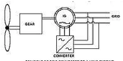
Fig 2. principle of DFIG connected to a wind turbine
The doubly-fed generator rotors are typically wound with 2 to 3 times the number of turns of the stator. This means that the rotor voltages will be higher and currents respectively lower. Thus in the typical ± 30 % operational speed range around the synchronous speed, the rated current of the converter is accordingly lower which leads to a lower cost of the converter. The drawback is that controlled operation outside the operational speed range is impossible because of the higher than rated rotor voltage. Further, the voltage transients due to the grid disturbances (three- and two-phase voltage dips, especially) will also be magnified. In order to prevent high rotor voltages - and high currents resulting from these voltages - from destroying
the IGBTs and diodes of the converter, a protection circuit (called crowbar) is used.
The crowbar will short-circuit the rotor windings through a small resistance when excessive currents or voltages are detected. In order to be able to continue the operation as quickly as possible an active crowbar has to be used. The active crowbar can remove the rotor short in a controlled way and thus the rotor side converter can be started only after 20-60 ms from the start of the grid disturbance. Thus it is possible to generate reactive current to the grid during the rest of the voltage dip and in this way help the grid to recover from the fault. A doubly fed induction machine is a wound-rotor doubly-fed electric machine and has several advantages over a conventional induction machine in wind power applications. First, as the rotor circuit is controlled by a power electronics converter, the induction generator is able to both import and export reactive power. This has important consequences for power system stability and allows the machine to support the grid during severe voltage disturbances (low voltage ride through, LVRT).
III. OPERATING PRINCIPLE OF
EXISTING SYSTEM
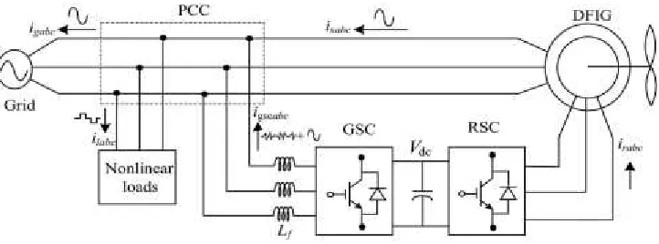
These nonlinear load harmonic currents are mitigated by GSC control, so that the stator and grid currents are harmonic-free. RSC is controlled for achieving maximum power point tracking (MPPT) and also for making unity
power factor at the stator side using voltage-oriented reference frame. Synchronous reference frame (SRF) control method is used for extracting the fundamental component of load currents for the GSC control.
Fig.3. system configuration.
IV. OPERATION PROPOSED SYSTEM
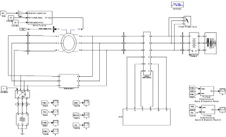
The investigated wind turbine system, as shown in Fig.4, consists of the basic components like the turbine, a gear (in most systems), a DFIG, and a back-to-back voltage source converter with a dc link. A dc chopper to limit the dc voltage across the dc capacitor and a crowbar are included. The back-to-back converter consists of a RSC and a LSC, connected to the
grid by a line filter to reduce the harmonics caused by the converter. A DVR is included to protect the wind turbine from voltage disturbances. Due to the short period of time of voltage disturbances, the dynamics of the mechanical part of the turbine will be neglected and the mechanical torque brought in by the
wind is assumed to be constant
Control of RSC
The main purpose of RSC is to extract maximum power with independent control of active and reactive powers. Here, the RSC is controlled in voltage-oriented reference frame. Therefore, the active and reactive powers are controlled by controlling direct and quadrature axis rotor currents (idr and iqr), respectively. Direct axis reference rotor current is selected such that maximum power is extracted for a particular wind speed. This can be achieved by running the DFIG at a rotor speed for a particular wind speed.
Control of LSC
The novelty of this work lies in the control of this GSC for mitigating the harmonics produced
by the nonlinear loads. The control block diagram of GSC is shown in Fig. Here, an indirect current control is applied on the grid currents for making them sinusoidal and balanced. Therefore, this GSC supplies the harmonics for making grid currents sinusoidal and balanced. These grid currents are calculated by subtracting the load currents from the summation of stator currents and GSC currents. Active power component of GSC current is obtained by processing the dc-link voltage error (vdce) between reference and estimated dc-link voltage (Vd∗ c and Vdc) through PI controller as
where kpdc and kidc are proportional and integral gains of dc-link voltage controller.
Vdce(k) and Vdce(k − 1) are dclink voltage
errors at kth and (k−1)th instants. I*gsc(k) and
i*gsc(k − 1) are active power component of
GSC current at kth and (k−1)th instants. Active power component of stator current (ids) is obtained from the sensed stator currents (isa, isb, and isc) using abc to dq transformation as
Fundamental active load current (ild) is obtained using SRF theory [33]. Instantaneous load currents (ilabc) and the value of phase angle from EPLL are used for converting the load currents in to synchronously rotating dq frame (_ild). In synchronously rotating frames,
V.EXISTING SIMULATION RESULTS
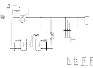
Fig 5. MATLAB/SIMULINK diagram of DFIG connected to WECS
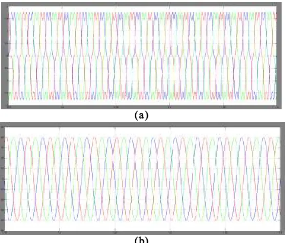
(a)
(b)
Fig 7 (a)Load current (Iabc1) (b) Load voltage (Vabc1)
(a)
(b)
Fig 9 stator current (Iabc stator)
(A)
(B)
(C)
VI. EXTENSION RESULTS
Fig 11. MATLAB/SIMULINK diagram of DFIG wind turbine system with DVR
(b)
(C)
(d)
CONCLUSION
The GSC control algorithm of the proposed DFIG has been modified for supplying the harmonics and reactive power of the local loads. In this proposed DFIG, the reactive power for the induction machine has been supplied from the RSC and the load reactive power has been supplied from the GSC. The decoupled control of both active and reactive powers has been achieved by RSC control. The proposed DFIG has also been verified at wind turbine stalling condition for compensating harmonics and reactive power of local loads. This DFIG-based WECS with an integrated active filter has been simulated using MATLAB/Simulink environment, and the simulated results are verified with test results of the developed prototype of this WECS. Steady-state performance of the proposed DFIG has been demonstrated for a wind speed. Dynamic performance of this proposed GSC control algorithm has also been verified for the variation in the wind speeds and for local nonlinear load.
In extension we observed that the DVR connected to a wind-turbine-driven DFIG to allow uninterruptible fault ride-through of grid voltage faults is investigated. The DVR can compensate the faulty line voltage, while the DFIG wind turbine can continue its nominal operation and fulfill any grid code requirement
without the need for additional protection methods.
REFERENCES
[1] D. M. Tagare, Electric Power Generation the Changing Dimensions. Piscataway, NJ, USA: IEEE Press, 2011.
[2] G. M. Joselin Herbert, S. Iniyan, and D. Amutha, “A review of technical issues on the development of wind farms,” Renew. Sustain. Energy Rev., vol. 32, pp. 619–641, 2014.
[3] I.Munteanu, A. I. Bratcu, N.-A. Cutululis, and E. Ceang, Optimal Control of Wind Energy Systems Towards a Global Approach. Berlin, Germany: Springer-Verlag, 2008.
[4] A. A. B. Mohd Zin, H. A. Mahmoud Pesaran, A. B. Khairuddin, L. Jahanshaloo, and O. Shariati, “An overview on doubly fed induction generators controls and contributions to wind based electricity generation,” Renew. Sustain. Energy Rev., vol. 27, pp. 692–708, Nov. 2013.
[5] S. S. Murthy, B. Singh, P. K. Goel, and S. K. Tiwari, “A comparative study of fixed speed and variable speed wind energy conversion systems feeding the grid,” in Proc. IEEE Conf. Power Electron. Drive Syst. (PEDS’07), Nov. 27–30, 2007, pp. 736–743.
[6] D. S. Zinger and E. Muljadi, “Annualized wind energy improvement using variable speeds,” IEEE Trans. Ind. Appl., vol. 33, no. 6, pp. 1444– 1447, Nov./Dec. 1997.
[7] H. Polinder, F. F. A. van der Pijl, G. J. de Vilder, and P. J. Tavner, “Comparison of direct-drive and geared generator concepts for wind turbines,” IEEE Trans. Energy Convers., vol. 21, no. 3, pp. 725–733, Sep. 2006.
with alternative schemes,” IEEE Trans. Energy Convers., vol. 17, no. 3, pp. 414–421, Sep. 2002. [9] E. Muljadi, C. P. Butterfield, B. Parsons, and A Ellis, “Effect of variable speed wind turbine generator on stability of a weak grid,” IEEE Trans. Energy Convers., vol. 22, no. 1, pp. 29– 36, Mar. 2007.
[10] R. Pena, J. C. Clare, and G. M. Asher, “Doubly fed induction generator using back-to-back PWM converters and its application to variable-speed wind-energy generation,” IEE Proc. Elect. Power Appl., vol. 143, no. 3, pp. 231–241, May 1996.
[11] S. Muller, M. Deicke, and R. W. De Doncker, “Doubly fed induction generator systems for wind turbines,” IEEE Ind. Appl. Mag., vol. 8, no. 3, pp. 26–33, May/Jun. 2002. [12] W. Qiao and R. G. Harley, “Grid connection requirements and solutions
for DFIG wind turbines,” in Proc. IEEE Energy 2030 Conf. (ENERGY’08), Nov. 17–18, 2008, pp. 1–8.
[13] A. Petersson, T. Thiringer, L. Harnefors, and T. Petru, “Modeling and experimental verification of grid interaction of a DFIG wind turbine,” IEEE Trans. Energy Convers., vol. 20, no. 4, pp. 878–886, Dec. 2005.
[14] H. M. Hasanien, “A set-membership affine projection algorithm-based adaptive-controlled SMES units for wind farms output power smoothing,” IEEE Trans. Sustain. Energy, vol. 5, no. 4, pp. 1226–1233, Oct. 2014.
[15] Z. Saad-Saoud, M. L. Lisboa, J. B. Ekanayake, N. Jenkins, and G. Strbac, “Application of STATCOMs to wind farms,” IEE Proc. Gener. Transmiss. Distrib., vol. 145, no. 5, pp. 511–516, Sep. 1998.
[16] G. O. Suvire and P. E. Mercado, “Combined control of a distribution static synchronous compensator/flywheel energy storage system for wind energy applications,”
IET Gener. Transmiss. Distrib., vol. 6, no. 6, pp. 483–492, Jun. 2012.
[17] D. Somayajula and M. L. Crow, “An ultra capacitor integrated power conditioner for intermittency smoothing and improving power quality of distribution grid,” IEEE Trans. Sustain. Energy, vol. 5, no. 4, pp. 1145– 1155, Oct. 2014.
[18] M. T. Abolhassani, P. Enjeti, and H. Toliyat, “Integrated doubly fed electric alternator/active filter (IDEA), a viable power quality solution, for wind energy conversion systems,” IEEE Trans. Energy Convers., vol. 23, no. 2, pp. 642–650, Jun. 2008.
[19] A. Gaillard, P. Poure, and S. Saadate, “Active filtering capability of WECS with DFIG for grid power quality improvement,” in Proc. IEEE Int. Symp. Ind. Electron., Jun. 30, 2008, pp. 2365–2370.
[20] A. Gaillard, P. Poure, and S. Saadate, “Reactive power compensation and active filtering capability of WECS with DFIG without any overrating,” Wind Energy, vol. 13, pp. 603– 614, 2009.
AUTHOR’S PROFILE:
MAHMAD MAZAHARUDDIN has received his B.Tech degree in the stream of Electrical and Electronics Engineering from Avanthi Institute Of Engineering And Technology (AIET-JNTUH). And M.Tech (Electrical Power
Systems) from
BRIG-JNTUH,Hyderabad,TS,India.