The Design of Two Axis Solar Tracking
System Based on Fuzzy Logic Control and
Efficiency Analysis
Ahmet KaysalResearch Assistant, Dept. of Electronics and Automation, Afyon Kocatepe University, Afyonkarahisar, Turkey
ABSTRACT:In this study, two-axis solar tracking system with microcontrollers of fuzzy logic control was designed to increase the efficiency output obtained from solar energy and it was compared with the fixed system.In the moving system, mini PV panels are used as sensors to find the real position of the sun and that geared DC motors in the mechanism with PWM signals obtained from the fuzzy logic controllers were conducted in an intelligent way. All day long the electrical data obtained from fixed and tracking system was transferred to a computer online with the Arduino Due card.The voltage, current and power data of both systems were analysed through Matlab/Simulink software. When the data obtained from the designed prototypes was studied microcontroller-based solar tracking system was observed to have an24.64% increase in efficiency according to the fixed system.
KEYWORDS:Solar Tracking System, Fuzzy Logic Controller, Photovoltaic Panel.
I.INTRODUCTION
Today, the industry is fast evolving and the thirst for electrical energy is correspondingly increasing. As the energy produced by the electricity plants relies on the fossil fuel energy sources for the most part this consumption has caused them to rapidly deplete. In addition, when the inability to issue large amounts of storage of electrical energy was incorporated into this problem the solute on to these problems a requirement to meet the current demand of the electrical energy and much higher efficiency in production and a preference for renewable energy sources as a source of energy occurred[1].Consequentlythemethods to obtain electricity from solar energy are evolving rapidly. Though technological advances to obtain electric energy from solar cells by way of photovoltaic method are swift, a very little part of the energy that can be obtained from the sun with the help of the solar cells can be converted into electricity, when accompanied with the low efficiency of solar cells. At this point, to obtain high yields from sunlight, the necessity of using systems that follow the sun arises solar tracking systems are the tracking systems,designed to increase energy they produce as solar panels follow the sun continuously during the day. Thanks to this system, a larger amount of radiation is observed and solar panels in this way increases daily performance and yield much better values the resulting energy yield increase is in the limit values of between25% and 55% [2].
system that uses sensors and LDR but also with that of LDR and webcam. As a result of analysis, the system which implements the LDR and the webcam performs much better from other systems [7]. Tudorache and Kreindler designed single axis solar tracking system for PV power plants. In the system, they used two LEDs to determine the position of the Sun and an IBL2403 smart motor driver for the movement of servo motor [8]. In their study, Tina et al. developed the prototype of smart solar tracking system by using nine photo diodes as sensors. Using the Matlabsoftware position of sun was determined with the voltage information from photo diodes [9].
In this study simulation of two axes solar tracking based on fuzzy logic control system in Matlab/Simulink software was created. By assembling electrical and mechanical components of the system, fixed system and data analysis with real time were examined in the Matlab software and their performances were compared.
II.MATERIAL AND METHODS
Solar cells consist of a combination of thin layers of − semiconductor. In the dark − characteristics of photo voltaic cell output are very similar to diode characteristics. When exposed to the light thanks to photons the current is supplied through electron movement. In the equivalent photovoltaic cell model, the basic model, an advanced diode model, an advanced two diode model and the other original models are implemented. A single diode model is the simplest model that is used to simulatea photo voltaic solar cell [10].
A. MATHEMATICAL MODELING OF PV CELLS
The circuit model equivalent to a single diode model commonly used for solar cells is given in Fig 1.The current source is the one generated depending on the solar radiation ( )and under the constant radiation and temperature its value is fixed. In the equivalent circuit model the given parallel resistance represents leakage current of the voltage and serial resistance represents drop in the output.
Fig.1 Equivalent circuit of a PV cell
Mathematical expression for the behaviour of the equivalent circuit model given in Fig 1 can be seen in equation (1).
=
−
+
−
1
−
+
(1)Where is the module voltage, is the diode dark current, is the number of cells in series in the module and is the PN junction thermal voltage defined as:
=
(
+ 273)
(2)B. FIXED SYSTEM
In fixed systems, solar cells are placed with a certain slope. Tilt angle will show variations according to regions and seasons. In the northern hemisphere PV systems are usually placed to the South with a particular point of view. To get the maximum yield from a fixed system the region's latitude angle ∅ and the sun's the position in the noon hours (north positive) should be taken in consideration. Accordingly, on 04 December 2016 the divergence angle of Afyonkarahisar, where the PV system was established was obtained from the equation (3) and equation (4) was obtained from the angle PV module formed with the horizon [12].
= 23.45 sin
360(284 + )
365
°
(3)= (
∅
± )°
(4)Where is the day of the year and ∅ is the latitude angle of the region, “+” for winter and “-” for summer. Fig 2 shows how monthly performance depends on PV module tilt angle.
Fig.2 Monthly PV cell performance as a function of collector tilt angle [13].
The block diagram of the fixed system whose experimental study was done is provided in Fig 3. This system is generally, composed of solar panel, solar charge regulator, battery, measurement group, invertor and electronic load.Numeric data such as current, voltage and power of the electricity derived from solar panel in the fixed system, was recorded by Matlab software running on an online computer.
C. TRACKING SYSTEM
Fig.3The block diagram of fixed and tracking system.
D. ELECTRICAL PARTS
In this study, 4 mini PV panels were used to determine the position of the sun automatically to increase the efficiency of 20 watt electrical energy power obtained from solar panels. While ACS712 microcontroller current transducer supplies the current data of the panel, data of the voltage is provided with the trimpot of 100KΩ on the newly designed
feeding card. Also the temperature of the panel is instantly checked with the PT100 temperature sensor. Linear actuator motors which provide the movement of the mechanical mechanism bearing the panel in two axis is controlled with MC33926 with motor driver and limit switches on actuator motors are used to prevent strain on mechanical parts. The data from sensors is collected in an online computer via the Arduino Due microcontroller. Fig 4 shows the correlation of the electrical and mechanical parts used in the system.
i. Photovoltaic (PV) Panel
Solar panels convert sunlight into electrical energy. When the sunlight hits the panels, direct current begins to be produced at the panels.Solar energy cells are connected according to the preferential power choices, either serial or parallel. The energy efficiency of a solar cell is measured with its yield. View of monocrystalline PV panelthat we use in this study is given in Fig 5.
Fig. 5 View of the two axis tracking system
ii. Arduino Due Microcontroller
Arduino Due is an Atmel SAM3X8E ARM Cortex-M3 based 32 bit microcontroller board. On the board are 54 digital input/output pins (12 of them can be used as PWM outputs), 12 analog inputs, 4 UART (hardware serial port), 84 MHz crystal, usb otg socket, 2 DAC (digital to analog converter), 2 x I2C, Jtag connector, ICSP connector, power socket, reset and erase button. Arduino Due microcontroller card used in the system can be seen Fig 6.
iii. Motors and Driver Module
The actuator motors used in the system convert rolling motion of electric engine to push and pull motion. While one of the actuator motor provides the movement of the panel in the East-West axis direction, the other provides a movement along the axis of North-South.
Fig.7 Using the dual MC33926 motor driver shield with an Arduino
Motor driver card which was designed with Arduino to drive engines which require high power bears two MC33926 ICs. The driver that supports from 5 to 28V voltage is able to provide a current of 3A per-motor. To be able to use without the Arduino, MC33926 card that supports up to 20 kHz PWM frequency was also equipped with control pins along the edge of the card. Connection of motor driver card with the Arduino Due can be seen in Fig 7.
A. TRACKING SYSTEM MODEL AND FUZZY LOGIC CONTROLLER DESIGN
In a fuzzy system fuzzy inference engine uses fuzzy sets and rule base instead of mathematical equations. In the fuzzy system two sources of information are taken in consideration as a combination,one being observation and measured values, and the other being the opinions of experts .This means that in addition to the numeric data base, existence of the verbal rule base is available. Expert opinions work to model out the uncertainties unknown in the system [14].
Fig.8 The block diagram of fuzzy logic controller
Fuzzy logic controller (FLC) based on Mamdani fuzzy inference system was designed to increase the efficiency of the energy obtained from track system and to obtain the desired quality power. The first of the two input signals is error signal ( ), and the second one is ( )/ the change of error signal according to time.Controller's output signal is PWM control signal that provides controls of dc motors to set the desired extent according to the position of the sun. For each rule, holistic inference of inference system is calculated with the equation (5).
=
∑
Here, N; number of rules, W; the weight of rules, Z; output level. The error signal ( )from the input variables of FLC and change signal in the error ( )/ are (negative big), (negative small), (zero), (positive small) and (positive big)as linguistic variables. Triangle type the membership function was used in fuzzy inference system. When creating rule base" " operator of logical operations is used. In Fig8 a block diagram of fuzzy logic controller designed in the system with four entries and two output variables is given.Table 1 shows the control rule base for the fuzzy logic controller.
Table 1.The membership functions for FLC
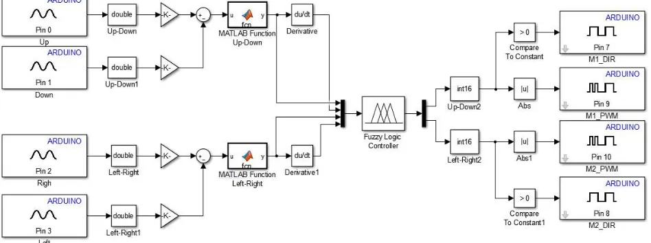
The FLC model in Matlab/Simulink software was used in the system. As seen in the block diagram of simulation given in Fig 9 data about the position of the sun provided by 4 sensors was read by 0, 1, 2, and 3 ADC input pins of Arduino Due microcontroller and after the difference was taken 1and 2 error signals were obtained. These error signals and the change of error according to time were applied to FLC block. According to the rule base of FLC output
signals were obtained from the 9 and 10 pins and they were applied to MC33926 motor driver module.
Fig.9 Simulation block diagrams of solar tracking system
Fig.10. Connection blocks of the tracking and fixed panels in Matlab/Simulink
III.EXPERIMENTAL RESULTS AND DISCUSSION
The efficiency of sunlight can show changes according to time and geographic structure. Turkey has favourable geographic coordinates, soithas the high solar energy potential. This experimental study was carried out in Afyonkarahisar/Dinar on a sunny day on 4 December 2016. The average temperature of the experiment day was try7.5℃and the average wind speed was 2 / [15].
Table 2. Voltage, current and power example values ofrelated to tracking and fixed systems obtained by the data recorded on the computer
Time (h:m)
Fixed Panel Solar Tracking Panel
I1 (A) U1 (V) P1 (W) I2 (A) U2 (V) P2 (W)
08:27 0,036 0,019 0,00067 0,050 0,026 0,00129
08:45 0,136 0,076 0,01026 0,362 0,275 0,09955
09:15 0,340 0,263 0,08942 0,613 1,189 0,72885
09:22 0,350 0,270 0,09450 0,686 1,623 1,11337
09:48 0,578 1,021 0,59013 0,975 3,730 3,63675
10:30 0,870 2,910 2,53170 1,212 5,750 6,96900
11:15 1,117 4,920 5,49564 1,382 7,490 10,3511
12:00 1,270 8,000 7,62000 1,450 8,500 11,9625
12:45 1,440 8,850 11,7360 1,515 8,950 13,5592
13:00 1,440 8,856 11,7930 1,470 8,900 12,9360
14:08 1,367 8,855 9,91075 1,407 8,900 10,3414
15:20 1,193 5,570 6,64501 1,270 6,280 7,97560
16:20 0,813 2,450 1,99185 0,979 3,712 3,63404
17:00 0,310 0,378 0,11718 0,412 0,371 0,15285
The angle of the fixed solar panel with the horizon was computed using equations (4) and (5) and it read60.54°. With the Sunrise (8:27) the system started to record the data and continued until (17:20) the sunset.Voltage, current and power data of both the solar tracking system and the fixed system was collected by an online computer all day. Some of this data can be seen in Table 2. When the data was analysed, the electrical output size of the solar tracking system, as expected, was higher than the fixed system.
In the chart of Fig 11 the voltage values of the both panels are compared during the time span from the sunrise to the sunset. When the graphics are examined voltage values between 11:30 – 14:30 are very close to each other but in the early hours of the morning and the sun sets the gap between the voltages values are observed to increase.
Fig.11.The voltage values of the tracking and fixed systems
Fig. 12. The current values of the tracking and fixed systems
the fixed and moving panels in Fig 13 is calculated, the solar tracker has produced 24.64% more power than the fixed system.
Fig.13. The power values of the tracking and fixed systems
IV. CONCLUSION
With smart solar tracking based on fuzzy logic control system it is intended the Sun's irradiance can be followed with maximum density. This experimental work proved that the tracking system is more efficient than the fixed system. Solar energy has become one of the important types of alternative energy sources, such reasons as accessibility, cost efficient in production and low priced installation costs have made it favourable. But one of the problems of solar energy technology is that we should be able to increase the yield of solar panel output power by collecting as much sun rays as possible. The system we designed will contribute a solution to this problem. Clearly the tracking system we designed improved the output yield by 24.64% when compared to the fixed panel. Besides actuator motors which enable the movement of the panel did not operate at maximum level and because it was controlled by the PWM modulation in smart mode power consumption was significantly reduced.
REFERENCES
[1] E. Yalçın, E. Çam and M. Luy, Load frequency control in four-area power systems using PID controller, Electrical – Electronics and Computer Engineering Symposium, Bursa, Turkey, 2010, 72-77.
[2] G. Bayrak, M.T. Gençoğlu, Design of two-axis solar tracking system and by PLC control, International Federation of Automatic Control, 6,
2011,407-411.
[3] A. Şenpinar, M. Cebeci, Evaluation of power output for fixed and two-axis tracking PVarrays, Applied Energy, 92, 2012, 677-685.
[4] A.Zakariah, J. J. Jamian and M. A. Yunus, Dual-Axis solar tracking system based on fuzzy logic control and light dependent resistors as feedback
path elements, IEEE Student Conference on Research and Development (SCOReD), 2015, 139-144.
[5] A. Kassem and M.Hamad, A microcontroller-based multi-function solar tracking system, IEEE Systems Conference (SysCon), 2011, 13-16.
[6] I. Abadi, A. Soeprijanto and A. Musyafa, Design of single axis solar tracking system at photovoltaic panel using fuzzy logic controller, 5th Brunei
International Conference on Engineering and Technology (BICET),2014, 1-6.
[7] H. A. Sohag, M. Hasan, M. Khatun and M. Ahmad, An Accurate and efficient solar tracking system using image processing and LDR sensor, 2nd
International Conference on Electrical Information and Communication Technology (EICT), 2015, 522-527.
[8] T. Tudorache and L. Kreindler, Design of a solar tracker system for PV power plants, ActaPolytechnicaHungarica, 7(1), 2010, 23-39.
[9] G.M. Tina, F. Arcidiacono and A. Gagliano, Intelligent sun-tracking system based on multiple photodiode sensors for maximization of photovoltaic
energy production, Mathematics and Computers in Simulation, 91, 2013, 16-28.
[10] H.R. Özçalık, Ş. Yılmaz and E. Kılıç, Forming the Mathematical of the Solar Cell by Means of Equivalent Circuit with a Diode and Investigation of
the Parameters, KSU Journal of Engineering Sciences, 16(1), 2013, 23-29.
[11] J.L. Diaz-Bernabe and A. Morales-Acevedo, Photovoltaic module simulator implemented in SPICE and simulink, 12th International Conference on
Electrical Engineering, Computing Science and Automatic Control (CCE), 2015, 1-5.
[12] J.A. Duffie and W.A. Beckman, Solar engineering of thermal processes (Canada: Wiley-Interscience Publication, 2013).
[13] R. Messenger and J. Ventre, Photovoltaic systems engineering (Florida: CRC Press LLC, 2004).
[14] Z. Şen,Principles of Fuzzy Logic and Modeling, (İstanbul: Water Foundation Publication, 2009).