CSEIT1833756 | Received : 25 April 2018 | Accepted : 05 May 2018 | May-June-2018 [ (3)5 : 18-22 ]
© 2018 IJSRCSEIT | Volume 3 | Issue 5 | ISSN : 2456-3307
Drawing Robot
Keyur Jain1, Akash Nair1, Prof. Shikha Singh2
1Student Electrical and electronics engineering, Indus University, Ahmedabad, Gujarat, India
2Assistant Professor Electrical and electronics engineering, Indus University, Ahmedabad, Gujarat, India
ABSTRACT
This document provides some basic information on Drawing robot that is basically a X-Y plotter based on CNC mechanism. Most of the plotter’s design available in market are based on bi-directional movement and square type model. In the proposed drawing robot design, axis movement are bounded on each other and belt driven mechanism is used for plotting. Stepper motors are used for X-Y movement and servo motors for plotter’s movement.
Keywords: Stepper motor, Servo motor, CNC driver.
I.
INTRODUCTION
Robotics is the branch of technology that deals with the design, construction, operation, and application of robots, as well as computer systems for their control, sensory feedback, and information processing.
The design of a given robotic system will often incorporate principles of mechanical engineering, electronic engineering and computer science (particularly artificial intelligence).
Though there are several models for plotter, this plotter is designed in most economical way and to provide high accuracy in plottings. Main advantage of this plotter is we can replace the tool based on any application such as engraving machine, laser cutting machine, painting any surface and drawing purposes.
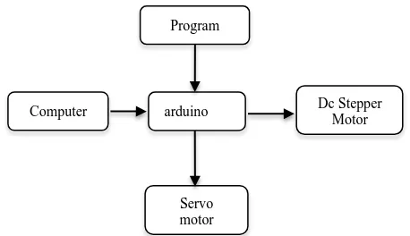
Figure 1. Block diagram of the given robot
In this paper, Arduino Nano and Uno are used to control the servo motor and stepper motors. Moreover, in several plotter design manufacturers use microcontroller to operate the Pulse Width Modulation based driver circuit which has in-built timer circuit in it which makes the user easy. But,when the user tries to modify the timer, they feel difficult to modify as they wish. Instead of that its easy to modify the arduino compare to microcontroller.
II.
METHODS AND MATERIAL
From Figure 1, we describe the software and hardware implementation for this paper
Computer
Servo motor Program
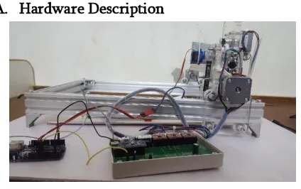
A. Hardware Description
Figure 2. complete hardware setup
Main components of the hardware design are Stepper motor, Servo motor, CNC board, A4988 driver, Aluminium section, GT2 pulley, timing belt, Arduino Nano and Arduino UNO.
1) Stepper motor
There several types of stepper motor: they are hybrid synchronous stepper, variable reluctance stepper, permanent magnet stepper. Main two models are unipolar and bipolar stepper motor. In this paper, 4-wire bipolar hybrid synchronous motor of 1.8 degree step angle is used for better positioning and accuracy. Functioning of motor is based on stepping action. There are several stepping modes. They are full step, half step, micro step. Normally the sequence for motor is A+ A- B+ B- .
Three stepper motors are used in this paper, two motors for Y axis movement and one motor for X axis movement.
In this paper we are using Nema 17 stepper motors.
Figure 3. Stepper motor
2) Servo motor
Tiny and lightweight with high output power. Servo motors can rotate approximately 180 degrees (90 in each direction), and works just like the standard kinds but smaller. In this paper servo motor is used for the movement of plotter in up and down
direction. Servo motor have inernal rotor controller with feedback therefore it is more preferable than stepper motor for plotter mechanism.
SG90 servo motor is used in this paper.
Figure 4. Servo motor
3) CNC board
A CNC Board is a device for connecting between differing interfaces. The most common type for CNC machines converts from a parallel connection to screw terminals for universal hook up. More advanced breakout boards incorporate signal filtering and protection, inputs for Limit Switches, Homing Switches and E-Stop, and output relays.
In this paper it is used to controller the stepper motor using A4988 driver.
Three stepper drivers and arduino nano398 are soldered on CNC board.
4) A4988 Stepper driver
The A4988 is a complete micro-stepping motor driver with built-in translator for easy operation. It is designed to operate bipolar stepper motors in full-, half-, quarter-, eighth-, and sixteenth-step modes, with an output drive capacity of up to 35 V and ±2 A. The A4988 includes a fixed off-time current regulator which has the ability to operate in slow or mixed decay modes.
Figure 5. A4988 driver.
5) Aluminium Section
sink. And also iron is heavier than aluminium. Based on the manufacturer profile size may vary.
6) Pulley GT2
Pulley can be made with different type of material such as plastics, steel, aluminium and nylon block. In this paper GT2 pulley are used. The GT2 pulleys are designed specifically for linear motion. They use a rounded tooth profile that guarantees that the belt tooth fits smoothly and accurately in the pulley groove, so when you reverse the pulley direction, there is no room for the belt to move in the groove.
Figure 5. Pulley GT2
7) Timing belt
There are several types of belt made of different material. In this paper, timing belt is used because of its accuracy and positioning. Timing belts are available in rubber, fiber re-in forced in rubber and Poly Urethane material with different circumference sizes such as 550mm, 1100mm are available. If application is based on the oil and water, then poly urethane belt is preferred. In this paper rubber timing belt is used having 1 mm pitch.
Figure 6. timing belt
8) Arduino NANO
Arduino NANO is small, friendy, complete microcontroller board based on ATmega328. The only difference between UNO and NANO is that no of pins in UNO is more compare to NANO, rest of the functionality remains same. Inthis paper NANO
is used to drive stepper driver.
Figure 7. Arduino NANO
9) Arduino UNO
Arduno UNO is a microcontroller based on
ATmega328. It has 16 digital I/O pins and 6 analog inputs. It contains everything needed to support the microcontroller; simply connect it to a computer with a USB cable or power it with a AC-to-DC adapter or battery to get started.
Figure 8. Arduino UNO B) Software description
1) Inkscape 2)GRBL controller
1)Inkscape
Figure 9. Inkscape software
2) GRBL controller
Grbl is a free, open source, high performance software for controlling the motion of machines that move, that make things, or that make things move, and will run on a straight Arduino. If the maker movement was an industry, Grbl would be the industry standard.
Figure 10: GRBL software
C) Working
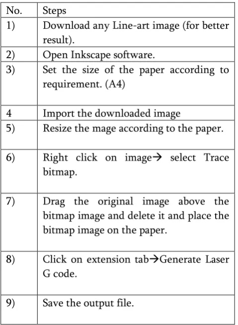
Table 1, Showing the process for conversion of image itno bitmap image to produce its G-code.
Table 1. Image conversion
No. Steps
1) Download any Line-art image (for better result).
2) Open Inkscape software.
3) Set the size of the paper according to requirement. (A4)
4 Import the downloaded image
5) Resize the mage according to the paper.
6) Right click on image select Trace bitmap.
7) Drag the original image above the bitmap image and delete it and place the bitmap image on the paper.
8) Click on extension tabGenerate Laser G code.
9) Save the output file.
Table 2, showing the steps the to load the generated G-code into the grbl software.
Table 2. Image loading
N0 Steps
1) Open the generated G code in Notepad ++ and replace the “M05 S0”
Command with “M05 S0\r\nG4 P1” and save it
2) Verify the comport use and Select the ComPort
3) Load the Generated G code into the Gbrl
4) Before begin set the x and y axis at one corner and Se that postion as zero positon
5) Press begin.
III.
RESULT
Figure 11, Shows the final image produced by the drawing robot.
Figure 11. Obtained image
IV. CONCLUSION
From this paper, we can generate several application based on x and y axis movement. Instead of pen, we can insert laser tool for cutting purposes. Moreover, this paper can be modified into three axis movement.
IV.
REFERENCES
[1].Model and Fabrication of CNC Plotter Machine Udit Pandey, Swapnil Raj Sharma , Department of Mechanical Engineering, BBD Engineering College, India, International Journal of Advanced Research in Computer and Communication Engineering ISO 3297:2007 Certified Vol. 6, Issue 6, June 2017.
[2].Mini CNC Plotter Aneeta Pinhiero1, Beljo Jose2, Tinsemon Chacko3, Nazim TN4 Electrical and Electronics Department, Amal Jyothi College of Engineering, Kanjirappally, Kerala, India,
INTERNATIONAL JOURNAL OF
INNOVATIVE RESEARCH IN ELECTRICAL, ELECTRONICS, INSTRUMENTATION AND CONTROL ENGINEERING Vol. 4, Issue 4, April 2014
[3].Mrs. R. Dayana, Gunaseelan P, Microcontroller Based X-Y Plotter, In ternational Journal of Advanced Research in Electrical, Electronics and Instrumentation Engineering, Vol. 3, Special Issue 3, April 2014.
[4].Allen G. Morinec, Power Quality Considerations for CNC Machines: Grounding, IEEE Transactions on Industrial Electronics, Vol. 38, No. 1, January/February 2002, pp. 3-11.