1
Modelling Design and Control of an Electromechanical Mass
Lifting System using Optimal and Robust control Method
Mustefa Jibril1, Messay Tadese2, Eliyas Alemayehu Tadese3
1 Msc, School of Electrical & Computer Engineering, Dire Dawa Institute of Technology, Dire Dawa,
Ethiopia
2 Msc, School of Electrical & Computer Engineering, Dire Dawa Institute of Technology, Dire Dawa,
Ethiopia
3 Msc, Faculty of Electrical & Computer Engineering, Jimma Institute of Technology, Jimma, Ethiopia
Abstract
In this paper, an electromechanical mass lifter system is designed, analyzed and compare using optimal and robust control theories. LQR and μ -synthesis controllers are used to improve the lift displacement by comparison method for tracking the desired step and sinusoidal wave signals input. Finally, the comparison simulation result prove the effectiveness of the electromechanical mass lifter system with μ -synthesis controller for improving the rise time, percentage overshoot, settling time and peak value of tracking the desired step displacement signal and improving the peak value for tracking the desired sinusoidal displacement signal with a good performance.
Keywords: μ –synthesis, linear quadratic regulator, optimal control, robust control
1. Introduction
In engineering, electromechanical systems combines strategies and tactics drawn from electrical engineering and mechanical engineering. Electromechanical systems specializes in the interaction of electrical and mechanical systems as an entire and how the two structures interact with every different. This manner is especially distinguished in systems such as those of DC or AC rotating electric machines which may be designed and operated to generate energy from a mechanical system (generator) or used to strength a mechanical impact (motor). Electrical engineering in this context additionally encompasses electronics engineering. Electromechanical systems are ones which have each electrical and mechanical processes. It operated by hand switch is an electromechanical element due to the mechanical movement causing an electrical output. Though this is proper, the term is normally understood to consult system which contain an electrical signal to create mechanical motion, or vice versa mechanical motion to create an electric signal. Often involving electromagnetic standards such as in relays, which permit a voltage or cutting-edge to manipulate every other, normally remoted circuit voltage or contemporary by means of robotically switching units of contacts, and solenoids, via which a voltage can actuate a moving linkage as in solenoid valves.
2. Mathimatical Model
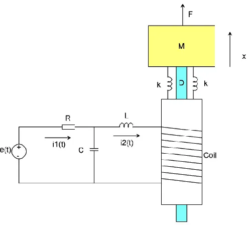
The electromechanical mass lifter system is shown in Figure 1 below.
2
Figure 1 Electromechanical mass lifter system
For a simplified analysis assume that the coil has a back emf of eb kb dx dt
and the coil current
produce a force Fc k i tf
on the mass M. For the electrical circuit applying KVL for loop 1 & 2 yields:Loop 1
1
1
2
1
e t Ri t i t i t dt c
Taking Laplace transform
1
1
2
1 1
1
E s RI s I s I s
sC sC
Loop 2
2
2 1
1
b
di t
e t L i t i t dt
dt c
Taking Laplace transform
2
2
1
1 1
2
b
E s sLI s I s I s
sC sC
3
b b
dx e t k
dt
Taking Laplace transform
3b b
E s sk X s
When a current i t2
flows through the coil a mechanical force is developed which is given by:
f 2
F t k i t
Taking Laplace transform
f 2
4F s k I s
Where
f
k Is the force constant N/A
For the mass system
22 2d x dx
F t M D kx
dt dt
Taking Laplace transform and rearrange
2
5 F s s MsDsk X s
Substituting Eqn (1) into Eqn (2) for i t1
and substituting Eqn (3) into the modified Eqn (2) and substituting Eqn (2) into Eqn (4) and finally substituting the modified Eqn (4) into Eqn (5) yields the transfer function the input voltage and the output displacement as:
4
3
2
2 2 2
f
f b f b
k X s
E s RLCMs L M RCD s RMLDRC Lkk k s RD Lkk k s Rk
The parameters of the electromechanical system is shown in Table 1 below
No Parameter Symbol Value
1 Resistor R 10 ohm
2 Inductor L 5 H
3 Capacitor C 0.001 F
4 Mass M 55 Kg
5 Spring Stiffness K 100 N/m
6 Damper D 10 N-s/m
6 Lenz constant kb 13
4
The electromechanical mass lifter system transfer function is
4 3 232
0.015 2 63 1516 2000
X s
E s s s s s
The state space representation of the system is
1 2 3 4 1 2 3 4130 4200 101070 133330 1
0 0 0 0 0
0 0 0 0 0
0 0 0 0 0
0 0 0 2133.3
x x x u x x x x y x x
3. The Proposed Controllers Design
In this section, the design of the electromechanical mass lifter system with µ-synthesis and LQR controllers is done respectively.
3.1µ-Synthesis Controller Design
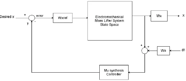
The electromechanical mass lifter system with µ-synthesis controller block diagram is shown in Figure 2.
Figure 2 Electromechanical mass lifter system with μ - synthesis controller system interconnections block diagram
5
1 n
y x d W
The controller’s acts at the y signal to provide the remarks displacement signal. The Wn block modelled the disturbance in the channel. Wn is given a disturbance noise of 0.04m.
0.04
n
W
W n is used to model the noise of the displacement sensor. The value of the error disturbance is scaled the use of the weight Wxref. Let us anticipate the maximum error disturbance is 0.08 m because of this
0.08
href
W
The weighting function Wx are used to keep the output displacement over the desired range. The water level W h1 is given as
1 3 x W s
The resulted μ -synthesis controller is
2 25 155 256 s K s s
3.2LQR Controller
LQR is a manage system that gives the fine viable overall performance with apprehend to some given degree of usual performance. The normal performance degree is a quadratic characteristic composed of state vector and control input.
Linear Quadratic Regulator (LQR) is the handiest concept of pole placement technique. LQR set of guidelines defines the most excellent pole location based on two cost function. To find out the most fulfilling profits, one have to outline the most beneficial performance index first off after which resolve algebraic Riccati equation. LQR does not have any particular approach to define the cost function to benefit the most appropriate profits and the value feature must be described in iterative way.
LQR is a manipulate scheme that offers the outstanding viable common overall performance with respect to a few given degree of overall performance. The LQR design problem is to design a state feedback controller K such that the objective function J is minimized. In this technique a feedback gain matrix is designed which minimizes the objective function an excellent way to benefit some compromise a number of the usage of manage attempt, the importance, and the speed of reaction at the manner to assure a stable system. For a continuous-time linear system defined by using
6 xAxBu With a cost functional defined as
T T
7J
x Qx u Ru dtWhere Q and R are the weight matrices, Q is required to be high quality precise or high quality semi-definite symmetry matrix. R is required to be positive definite symmetry matrix. One practical method is to Q and R to be diagonal matrix. The value of the factors in Q and R is related to its contribution to the cost function J. The feedback manage regulation that minimizes the value of the cost is:
8 u Kx6
1
9
T
K R B P
And P can be located through solving the continuous time algebraic Riccati equation:
1
0 10
T T
A PPA PBR B P Q
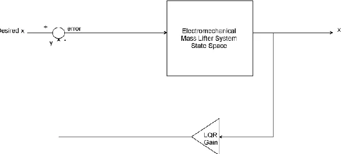
The value of weighted matrix Q (country variable) and R (control variable) is based upon on designer. Designer pick out the right cost of Q and R to discover the perfect advantage matrix K the usage of MATLAB. The State variable feedback configuration is shown below in Figure 3.
Figure 3 State variable feedback configuration
By taking
And R=1
The value of obtained feedback gain matrix K of LQR is given by
K= [0.0023 0.0581 0.0766 0.0000]
4. Result and Discussion
Here in this section, the comparison of the electromechanical mass lifter system with μ –synthesis and LQR controllers for tracking the desired output displacement using a step and sinusoidal wave signals.
4.1Comparison of the electromechanical mass lifter system with μ –synthesis and LQR controllers for a Desired Step Displacement Signal
The Simulink model for the electromechanical mass lifter system with μ –synthesis and LQR controllers for a desired step displacement signal is shown in Figure 4 below.
5 0 0 0 0 5 0 0 0 0 5 0 0 0 0 5 Q
7
Figure 4 Simulink model for the electromechanical mass lifter system with μ –synthesis and LQR controllers for a desired step displacement signal
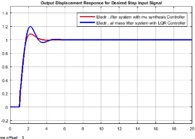
The simulation result of the comparison of the electromechanical mass lifter system with μ – synthesis and LQR controllers for a desired step displacement signal is shown in Figure 5 below.
Figure 5 Simulation result of the comparison of the electromechanical mass lifter system with μ –synthesis and LQR controllers for a desired step displacement signal
8
Table 2 Performance measurement of a step response
No Performance measure μ –synthesis LQR
1 Rise time 1.12 sec 1.2 sec
2 Percentage Overshoot 9.09 % 16.66 % 3 Settling time 4 sec 5.8 sec
4 Peak value 1.1 m 1.21 m
Table 2 shows that the electromechanical mass lifter system with μ –synthesis improve the rise time, percentage overshoot, settling time and peak value for tracking the desired step displacement signal with a good performance.
4.2Comparison of the electromechanical mass lifter system with μ –synthesis and LQR controllers for a Desired Sinusoidal Displacement Signal
The Simulink model for the electromechanical mass lifter system with μ –synthesis and LQR controllers for a desired step displacement signal is shown in Figure 6 below.
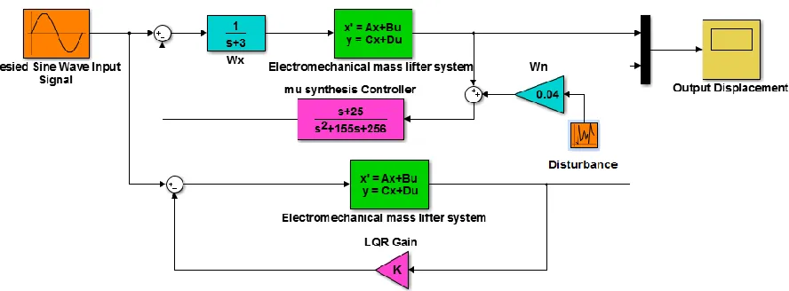
Figure 6 Simulink model for the electromechanical mass lifter system with μ –synthesis and LQR controllers for a desired sinusoidal displacement signal
9
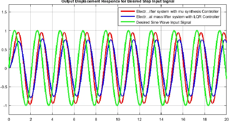
Figure 7 Simulation result of the comparison of the electromechanical mass lifter system with μ –synthesis and LQR controllers for a desired sinusoidal displacement signal
Table 3 Numerical peak values of the desired sinusoidal displacement signal simulation output
No Systems Peak value
1 Desired Input signal 1 m 2 μ –synthesis 0.97 m
3 LQR 0.7 m
Table 3 shows that the electromechanical mass lifter system with μ –synthesis improve the peak value for tracking the desired sinusoidal displacement signal with a good performance.
5. Conclusion
In this paper, modelling, design, analysis and control of the electromechanical mass lifter system with μ –synthesis and LQR controllers is done with the aid of Matlab/Simulink Toolbox. The proposed controllers are compared for the mass lifting mechanisms by improving the performance of the system to track the desired mass lift displacement. Step and sinusoidal signals are used as a desired displacement signals to be tracked by the system. The electromechanical mass lifter system with μ – synthesis controller improve the performance of the system by 90.1 % for the desired step displacement input and 97 % for the desired sinusoidal displacement input. Finally, the comparison simulation result prove the effectiveness of the electromechanical mass lifter system with μ -synthesis controller.
Reference
10
[2].Mustefa Jibril et al. “Quarter Car Active Suspension System Design using Optimal and Robust Control Method” International Research Journal of Modernization in Engineering Technology and Science, Vol. 02, Issue 03, 2020.
[3].Lijing D. et al. “Design and Advanced Control of Intelligent Large Scale Hydraulic Synchronization Lifting Systems” Journal of Control Science and Engineering, Vol. 2019, Article ID. 4641289, 10 pages, 2019.
[4].A. B. Emmanuel et al. “Investigating Efficiency of a Five Mass Electromechanical System Having Damping Friction, Elastic Coupling and Clearance” International Journal of Engineering Research and Technology, Vol. 6, Issue 6, 2017.
[5].Vytautas K. et al. “Research of Lifting Equipment Dynamics” Journal of Vibroengineering, Vol. 16, Issue 4, pp. 2082-2088, 2014.