Direct
Methanol Fuel Cells
TECHNOLOGICAL ADVANCES AND FURTHER REQUIREMENTS
By
M. F!
Hogarth and
G.
A. Hards
Johnson Matthey Technology Centre
The direct methanol fuel cell ( D M F C ) has been considered as the ideal fuel cell system since it produces electric power by the direct conversion of the methanol fuel at the fuel cell anode. T h i s is more attractive than the conventional hydro- gen fuelled cells, particularly f o r transportation applications, which rely on bulky and o f e n unresponsive reformer systems to convert methanol, or other hydrocarbon fuels, to hydrogen. However, commercialisation of tho D M F C has been impeded by its poor performance compared with hydrogenlair systems, the major limitation being the anode performance which requires highly efficient methanol oxidation catalysts. Such catalyst materials have been sought, and it appears that only platinum-based materials show reasonable activity and the
required stability. The recent application of proton exchange membrane elec- trolyte materials has extended the operational temperature of D M F C s beyond those attainable with traditional liquid electrolytes, and this has led to major improvements in performance over the last f i v e years. T h i s article describes some key work tackling the above limitations and suggests that the D M F C i s approaching the stage where it m a y become a commercially viable alternative to hydrogenlair systems.
Fuel cells have attracted attention as an alter- native to internal combustion engine (ICE) tech- nology, since they offer numerous benefits, including low or even zero emissions, higher efficiency and reliability. Batteries, which are another alternative technology, offer the prospect of a true local zero-emission vehicle, however, there are environmental and engineering draw- backs to all the current types of battery, and lim- itations to the distances offered by battery sys- tems, before recharging is required. Battery systems are thus only viewed as a short term solution, and fuel cell systems represent the best possible option in the longer term.
A fuel cell is an electrochemical engine which can convert the free energy change of a chem- ical reaction directly into electrical energy. This may, for example, be the catalysed electro- chemical reaction between hydrogen and oxy- gen to produce water. This is analogous to the combustion process which occurs in a heat engine, however, in a fuel cell this can take place
at much lower temperatures leading to higher efficiencies and reduced polluting emissions. A variety of types of fuel cells are under develop- ment, each with advantages and limitations.
Current
Fuel
Cell
Technologies
\
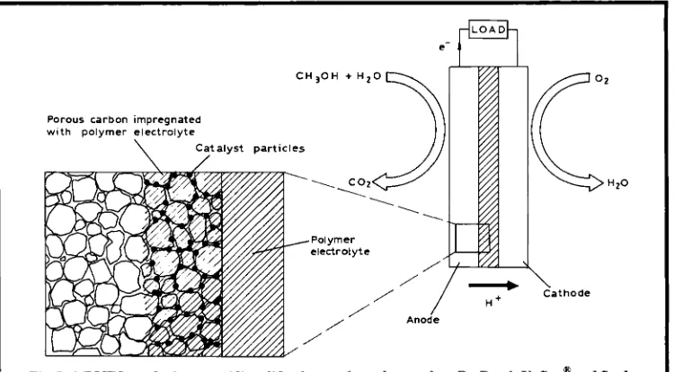
C H s O H + H 2 0Porous carbon impregnated w i t h polymer electrolyte
\
C a t a l y s t p a r t i c l e s- \ Cathode
H +
Fig. 1 A DMFC employing an acidic solid polymer electrolyte such as Du Pont’s Nafion” and finely dispersed platinum electrocatalyst supported on porous carbon electrodes
(PEMFC) technology has advanced in the last few years to the point where demonstration devices have been successfully implemented within vehicles. These cells use platinum-based catalysts to promote the electrode reactions, and a solid acidic proton conducting polymer elec- trolyte, often Du Pont’s Nafion@ perfluorinated sulphonic acid-type materials. However, the pre- sent PEMFC powered vehicles are almost exclu- sively based on the use of pure hydrogen as the fuel. While this may be a more than accept- able fuel option for transportation applications involving larger, depot based, fleet vehicles, such as transit buses, it is unlikely that this will be suitable for small, privately owned cars, due to fuel distribution, handling and storage diffi- culties and on-vehicle space and weight con- straints. Thus, methanol has attracted interest as the fuel of choice, because of its compati- bility with the existing distribution networks and its high energy density.
The use of methanol offers two distinct approaches. The currently favoured option involves an on-board reformer system which converts methanol into a hydrogen-rich gas which can then be consumed by the fuel cell. However, this fuel feed is diluted with carbon
dioxide and possibly nitrogen, and may contain traces of carbon monoxide which acts as a cat- alyst poison. Carbon monoxide can be removed firom the fuel feed with water gas shift and pref- erential oxidation reactors, but the removal can reduce the overall system efficiency and increase the weight, volume, start-up time and response to changes in power demand of the system.
In terms of system simplicity, the alternative and more desirable option is to use the direct methanol fuel cell - DMFC - where methanol fuel is supplied directly to the cell. However, there are drawbacks to this system which reduce its power output and efficiency. Therefore a num- ber of research programmes have been under- taken to find both more active anode catalysts for promoting methanol oxidation and more advanced electrolyte materials to combat fuel cross-over. The latter is essentially a chemical ‘short circuit’ which results in a mixed potential at the cathode, greatly reducing its efficiency.
Principles of
the
DMFC
Ideal cathode p o t e n t i a l
- - -
-
61
Cell voltage ( < 1 1 8 V )1 1 8 V
Anode kinetic loss
I c
CURRENT, A
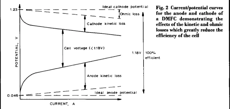
Fig. 2 Current/potential curves for the anode and cathode of a DMFC demonstrating the
effects of the kinetic and ohmic
losses which greatly reduce the efficiency of the cell
loo"/. e t f icient
shown in Equation (i). The DMFC must con- tain an acidic electrolyte to aid carbon dioxide rejection, since insoluble carbonates form in alkaline electrolytes. The protons produced a t the anode migrate through the polymer elec- trolyte to the cathode where they react with oxy- gen (usually from the air) to produce water, as shown in Equation (ii). The electrons produced a t the anode carry the free energy change of the chemical reaction and travel through the exter- nal circuit where they can be made to do use- ful work, such as power an electric motor. The overall cell reaction, as shown in Equation (iii), is therefore the reaction of methanol and oxy- gen to produce water and carbon dioxide. In a practical system, these reactions are promoted by the incorporation of platinum-based elec- trocatalyst materials in the electrodes.
CH30H
+
H20 -P C02+
6H'+
6e-Eonode = 0.046 V Anode reaction 0)
1 %On
+
6H'+
615 -P 3H20Eou&de = 1.23 V Cathode reaction (ii)
CHsOH
+
1%0,+
H20-P C02 + 3Hz0ECa = 1.18 V Cell terminal voltage (iii) In principle, methanol should be oxidised spontaneously when the anode potential is above 0.046 V, with respect to the reversible hydro- gen electrode (RHE). Similarly, oxygen should be reduced spontaneously when the cathode
assumes a potential below 1.23 V. In reality, and in common with all fuel cell types, poor elec- trode kinetics (kinetic losses) cause the elec- trode reactions to deviate from their ideal ther- modynamic values so as to incur a practical reduction of the extremely high theoretical effi- ciency possible from the cell. The real behav- iour of the individual electrodes in the DMFC system is shown in Figure 2. In practice, a far more positive potential is required at the anode and a more negative potential at the cathode to accelerate the reactions to a reasonable rate. Besides kinetic losses, there are ohmic losses deriving from the internal resistance of the fuel cell. Hence, the output of a real DMFC is sub- stantially lower than that of the ideal cell, which would give 1.18 V at any current rating.
OH
H OH
,
!
I
H
OH H%,> f
I
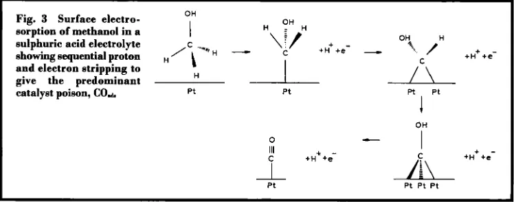
Fig. 3 Surface electro-sorption of methanol in a sulphuric acid electrolyte
showing sequential proton H/c,-'***H
-
+H++e--
+H++e-and
give electron the predominant stripping to H
/c\
7
Ptcatalyst poison,
Cod
Pt P tOH
I
0
-
+H++&
111 C
1
P t
I +
-+H +e
/c\
Pt Pt P t
competitive with its hydrogen fuelled counter- parts, lower power densities of 200 to 300 mW/un* need to be attained at cell voltages of 0.5 V.
Kinetic Limitations
The poor electrode kinetics at the anode and cathode result from the electrochemical processes being much more complex than Equations (i) and (ii) suggest. Each oxygen mol- ecule requires the transfer of four electrons for complete reduction. The simultaneous transfer of these electrons is difficult to achieve, and in fact only partial electron transfer takes place, leading to the formation of surface intermedi- ates, such as superoxide. Using a platinum elec- trocatalyst allows the stabilisation of these inter- mediates and permits the reaction to proceed at a reasonable and useful rate. The catalyst may also accelerate the reaction by opening up new reaction pathways. The picture is even less clear for the methanol reaction and the electro-oxi- dation of methanol again only occurs at a use- ful rate in the presence of platinum or a plat- inum-based electrocatalyst. Therefore this reaction has remained an active focus of research, and substantial studies into this process are pre- sent in the literature. The discrepancies between sets of experimental data may be due to the wide range of experimental conditions.
The electro-oxidation of methanol to carbon dioxide requires the transfer of six electrons, but it is highly unlikely that these electrons will trans-
fer simultaneously. It is also unlikely that par- tial electron transfer will lead to the formation
of a range of stable solution intermediates. Clearly, there must be surface adsorbed species present on the surface of the platinum electro- catalyst across its useful potential range, and it is these species which are responsible for the poor catalytic activity of platinum towards methanol electro-oxidation.
The postulated mechanisms for methanol elec- tro-oxidation were reviewed by Parsons and Vandernoot (2), and can be summarised as: Step 1 : Electrosorption of methanol onto the substrate to form carbon-containing interme- diates.
Step 2: Addition of oxygen (&om water) to the adsorbed carbon-containing intermediates to generate carbon dioxide.
In the fist process, very few materials are able to electrosorb methanol, and in acidic elec- trolytes only platinum-based electrocatalysts have the required activity and chemical stabil- ity. The adsorption mechanism is believed to take place through the sequence of steps shown in Figure 3 (3-5). The electrosorption of methanol on the surface of platinum occurs with sequential proton and electron stripping, giv- ing the main catalyst poison, linearly bonded carbon monoxide (Pt-CE 0). Subsequent reac- tions are believed to involve oxygen transfer to the Pt-CO species to produce carbon dioxide.
(iv) Pt
+
HzO + Pt-OH.d,+ H'
+
e-Pt-OHab
+
P t - c o a d e + Pt+
coz
+
H'+
e- (V)w
I
a YI
3
YI
L
>
>
E
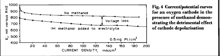
Fig. 4 Currentfpotential e w e s
for an oxygen cathode in the presence of methanol demon- strating the detrimental effect of cathode depolarisation N O methanol
7 00
600 IM methanol added t o electrolyte
w- 5 0 0
0 . 5 m g Ptlcm’ 4 00
2 0 40 6 0 80 100 120 140 160 180 2 0 0
CURRENT DENSITY, mAlcm*
bonded -toads species and further chemisorp- tion of methanol cannot proceed until the sur- face bound COads is oxidised fiom the platinum surface. But at these potentials this process occurs at an insignificant rate, and hence the platinum surface remains poisoned throughout its useful potential range. This had led to an intensive search for alternative materials which can oxidise methanol at lower overpotentials, and in particular for additional secondary mate- rials that might combine with platinum to pro- mote the above processes.
Advanced Materials
Some of the advanced materials that have been developed display enhanced activities, and there are a number of possible explanations to account for this. The most likely are:
(a) The secondary metal (for example, ruthe- nium) modifies the electronic properties of the catalyst, weakening the chemical bond between platinum and the surface intermediate. (b) The secondary metal (for example, ruthe- nium, tin, lead and rhodium) is unstable and leaches out of the alloy leaving a highly reticu- lated and active surface. This results in a higher number of extended step sites associated with the methanol electrosorption process. In addi- tion, these low co-ordinate sites may be much more easily oxidised, giving rise to Pt-OH.d, species at potentials far below that at which pla- nar platinum is oxidised.
(c) The secondary metal (such as ruthenium, tin and tungsten) is able to provide a site with -OK&, adjacent to the platinum, through a spill- over process. Hence, the catalyst activity is gov- erned by the potential at which the secondary metal oxidises and donates -OH,d, to adjacent
platinum sites. For materials such as ruthenium, this can occur at significantly lower potentials, below 250 mV, than is possible on a platinum surface (6-9), and indeed, at present the most active catalysts are based on platinum- ruthenium alloy materials.
Half Cell Data
The development of the DMFC was pioneered in the 1960s and 1970s by Shell and Exxon- Alsthom using liquid sulphuric acid and alka- line electrolytes, respectively. However, these programmes failed to produce stacks with suf- ficiently higher power densities, due to poor electrode kinetics and severe fuel cross-over between the electrodes. In sulphuric acid elec- trolyte, methanol cross-over was a particular problem, since both the anode and cathode cat- alysts were based on platinum. The performance of the cathode is reduced due to the ability of the platinum to electrochemically oxidise any methanol reaching it by diffusion from the anode. This can be seen in Figure 4 from half cell data, which are routinely used to measure the current versus voltage relationships of the individual electrodes. Clearly, the electrode effi- ciency is considerably reduced even when only low methanol concentrations are added to the electrolyte in the cell. The anode performance in sulphuric acid electrolytes was much lower than the target levels, with half cell data in the 1980s typically having current densities of 20 to 25 mA/cm2 at 0.4 V (vs. RHE) for anodes with platinum loadings of 0.5 mg/cm2 (1 0).
the operating temperature of the cell from 60°C to close to 100°C, and this coupled with the pos- sibility of enhanced intrinsic kinetics by use of the perfluorosulphonic acid electrolyte has led to the improved performances. Electrocatalyst developments have also continued and have cen- tred around the need for stable materials with higher intrinsic activity for methanol electro- oxidation. The group at the University of Newcastle upon Tyne (1 1) have reported Nafion@ containing platinum-ruthenium elec- trodes, with platinum loadings of 3.0 mg/cm2, achieving over 200 mA/cmz at 0.3 V at 80°C. The Jet Propulsion Laboratory in the U.S. has been working with lower platinum loading anodes (0.5 mg/cm2) which will be required for low cost target applications, such as trans- portation, and has reported over 100 mA/cmz at 0.4 V, at 60°C (12).
Recent work in the DMFC programme at Johnson Matthey indicates that it is also possi- ble to improve further the intrinsic catalyst activ- ity of the platinum-ruthenium materials for DMFC applications. Figure 5 shows the meth- anol oxidation activities of electrodes fabricated from 20 wt.
YO
platinum and 20 wt. % platinum- 10 wt. % ruthenium catalysts supported on car- bon black and comprising a soluble form of the polymer electrolyte, bound as a thin layer between a Nafion"-117 membrane and current collecting substrate. One important consider- ation, rarely mentioned in the literature, in deter- mining catalyst activity, is measuring activity in terms of real metal surface area (mA/cm* plat-inum). This is determined by the in-situ mea- surement of chemisorption of a monolayer of
carbon monoxide on the metal surface. The monolayer is then electrochemically oxidised from the surface to produce a charge which can be equated to the total electrochemical metal area available for reaction. This technique allows catalysts to be characterised independent of sur- face area, and readily identifies materials which have higher intrinsic activities. Platinum-ruthe- nium materials clearly possess substantially higher intrinsic activities than platinum, with the Type I1 platinum-ruthenium catalyst being significantly more active than the standard Type I platinum-ruthenium.
Single Cell
Data
There are a number of engineering criteria associated with the design and construction of a DMFC. The wide range of operating tem- peratures possible with a solid polymer elec- trolyte system means that methanol can be sup- plied either as a liquid or a vapour. Vapour systems, while offering higher performance and improved mass transport, are more complex as they require additional hardware to provide cooling. Fuel preheating is also necessary before injection; this carries a large energy penalty. The simplest systems from the engineering stand- point appear to be liquid-feed systems. Circulating the liquid fuel mixture prevents excessive heating of the cell, thus reducing the number of components and the size of the sys- tem. It is therefore not surprising that the major- ity of fuel cell research groups have chosen to construct liquid-feed systems.
In the U.S.A., the Advanced Research Projects Agency (ARPA) regards the DMFC as a
---
I
I
20wt.%Pt lOwt V.Ru(TypeI1 20Wt.% Pt
4 0 0
300
20wt %PtlOwt.%Ru (TypeID
Fig.5~urrentlpotentia1eurves 2oof
.
, , ,1
for anode half cell electrodes
containing platinum and u- l o o
platinum-ruthenium catalyst
materials at 80°C in 2M 0 2 0.4 0 6 0 8 1
aqueous methanol
>
potential mobile power source and also as a possible replacement for some of the primary batteries which are widely used b y U.S. military forces. Several groups, funded by AFU'A and the U.S. Department of Energy, have been col- laborating to develop DMFC tech- nologies. These groups include the Jet Propulsion Laboratory OpL) and Giner Inc., Los Alamos National Laboratory (LANL) and International Fuel Cells (IFC). I n Europe, the European Commission has actively funded DMFC projects for the past ten years under the framework of the Joule Programmes, and several groups have been active during this period; the most successful being Siemens (Germany) and Newcastle University. Johnson Matthey has recently been collaborat- ing with Siemens and Innovision (Denmark) under the framework of 'Joule 3' to develop a fuel cell stack. This programme aims to develop highly effi- cient DMFC stacks operating with liquid fuel at ambient pressures.
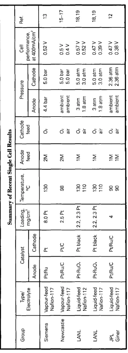
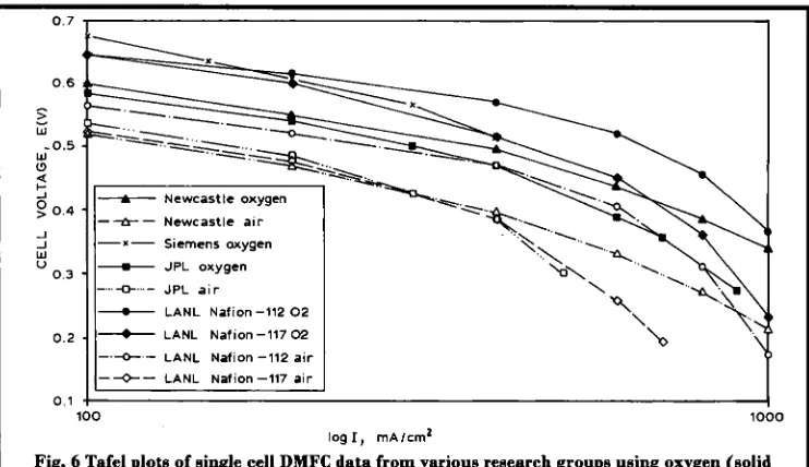
The above groups have achieved a wide range of cell performances using a variety of electrode compositions and operating conditions; this makes direct comparison of the data difficult, see the Table. The minimum goal required for commercialisation of fuel cells operat- ing on methanol and air is judged to be about 200 mW/cm2 at a cell voltage of 0.5 to 0 . 6 V. Some recent results achieved for single cell work b y the above mentioned groups are compared in Figure 6. Data plotted with a broken line correspond to the cell operation with air as oxidant, the solid lines rep- resenting data obtained on pure oxygen operation.
Siemens have developed their single cell technology around highly loaded unsupported platinum-ruthenium black anodes (4 mg/cm2) and platinum black cathodes (4 mg/cmz), operating at high
Group
Cathode 5.0
bar
5.0
bar
5.0
bar
5.0atm 3.0atm 5.0atm 3.0
atm
2.36
atm
2.36
atm
Siemens Newcastle LAN
L
LAN
L
JPL Giner performance, at
400mA/cm2 0.52V 0.5V 0.4V 0.57
V
0.52
V
0.47
V
0.39V 0.47
V
0.38
V
Type/
Electrolyte Vapour-feed Nafion-117 Vapour-feed Nafion-117 Liquid-feed Nafion-I
12
Liquid-feed Nafion-117 Liquid-feed Nafion-I
17
Catalvst
Anode Pt/Ru Pt/R
u/C
Pt-RuOx Pt-RuOx Pt/Ru/C Cathode Pt Pt/C Pt
black Pt black PtlRulC Summary of Recent Single Cell Results Loading ,
mg/crn2 8.0
Pt 2.5 Pt 2.2. 2.3 Pt 2.2, 2.3 Pt 4 Temperature.
OC 130 98 130 110 130 110 90 90 Anode feed 2M 2M 1M 1M 1M 1M Cathode feed
02 02 air 02 air 02 air 02 air
Pressure
I
Cell
Anode 4.4
bar
ambient ambient 3
atm 1.8 atm 3 atm 1.8 atm
0.7 1 I
Fig. 6 Tafel plots of single cell DMFC data from various research groups using oxygen (solid
lies) and air (broken lines) showing the high performanma achieved by these groupe
temperatures and pressures ( 1 3). Their best data show a high performance of 0.52 V at 400 mA/cmz and 130°C with pressurised methanol/ water vapour and oxygen at 4.4 bar and 5 bar, respectively. This produces a respectable power density of about 200 mW/cm2 which meets the target for a practical device, although this was achieved with pure oxygen. Durability testing of the single cell shows that stability is not yet sufficient for practical applications (1 4). However, following the successful demonstra- tion of such high performances, Siemens are currently working with Johnson Matthey and Innovision to develop cost effective cells that operate under more realistic conditions.
The Newcastle group has considered both liquid-feed and vapour-feed systems, with elec- trodes loaded at 2.5 mg platinudcm’ ( 15-1 7). A maximum performance of 0.5 V at 400 mA/cm2 was achieved at 98°C with oxygen at
5 bar pressure and 2 M methanouwater vapour at 200°C. The maximum power output with oxygen was over 350 mW/cm2 at 1.2 Nan2. With pressurised air, the cell voltage fell to 0.4 V at
400 mA/cm2, with a maximum power output of
220 mW/cmz. However, at a practical cell volt- age of 0.5 V the cell was able to generate only
50 mW/cm*, which is still somewhat short of the target 200 mW/cm2. Good short term sta- bility of the electrode assemblies was, however, reported.
JPUGiner Inc. present cell data of 0.47 and 0.38 V at a current density of 400 mA/cmz for their liquid-feed DMFC system operating at 90°C with 2.26 atm oxygen and air pressure, respectively (1 2). They also present impres- sive results for electrodes with low platinum loadings of 0.5 mg/cmz, which are capable of cell voltages near 0.5 V at a current density of 300 mA/cm2 at 95°C.
Data f h m LANL (1 8,19) are also very impres- sive with a best performance of 0.57 V at 400
d u n 2 for oxygen operation. This was achieved using Nafion@- 1 12 membrane, which is thinner than the currently used Nafion@-117. The enhanced performance is a result of the reduced internal resistance of the cell. The catalysts con- sisted of unsupported platinum/RuO. at the anode and platinum black at the cathode.
LANL
using high gas pressures and flow rates. The performance of the
LANL
cell in air was 0.52 V at 400 d c m Z at 110°C with anode and cath- ode pressures of 1.8 and 3 atm, respectively. It is unclear whether LANL are encountering enhanced fuel cross-over with the thinner N&on"-l12 membranes, as would be expected. They do, however, suggest that the cell perfor- mance is limited by the anode catalyst activity, and that their cathode exhibits a degree of methanol tolerance. The performance of their electrode with Nafion"-117 is very similar to the data presented by the Newcastle and JPL groups.Summary and
Future
Opportunities
In the last few years there has been a consid- erable improvement in the activity of methanol electro-oxidation catalysts, through improved operating conditions and better dispersion and control of the composition of existing plat- inum-ruthenium materials. Electrode technol- ogy has also advanced with the introduction of solid polymer electrolytes, such as Nafion", which has extended the operational tempera- ture and reduced the complexity of modern cells. The single cell data presented by various groups demonstrate the influence of parame- ters such as temperature, pressure, concentra- tion of reactants and electrode structure. The present level of technology requires high tem- peratures (1 30°C) and pressures before prac- tical cell power densities can be obtained.Most groups appear to use high noble metal loading of up to 4 mgkmz on the anode to increase the methanol turnover to a useful rate. This level of catalyst loading is too high for transportation applications and clearly indicates that the anode catalyst activity has still to increase, perhaps by a factor of at least ten, to reduce the noble metal loadings to more acceptable levels of below 0.5 mgk3n2. Optimisation of the electrode structure, leading to higher catalyst utilisation, will also contribute to increased cell performance.
Methanol cross-over from the anode to the cathode appears to be a major limitation at pre- sent. This is reflected in the high platinum cat- alyst loadings and the high gas pressure and flow rates which are necessary for reasonable cath- ode performance. The performance of the DMFC would be improved considerably if a methanol-impermeable electrolyte or a methanol-tolerant cathode existed. In order to minimise the effects of methanol cross-over, alternative membrane materials have been sought. Present electrolyte materials are restricted by poor water management and there- fore can only operate at temperatures below 100°C at ambient pressures. If the operational temperature could be increased to 150°C at ambient pressures, this would considerably enhance the kinetics of the anode reaction. However, this requires new materials which do not require humidification to maintain high conductivity.
An alternative to new membrane technology is to employ methanol tolerant cathode cata- lysts. A possible class of materials are high sur- face chevrel phase composites which consist of molybdenum, ruthenium and sulphur. Although these may not offer the same oxygen reduction performance as platinum-based mate- rials, this may outweigh the performance loss attributable to methanol cross-over seen with platinum-based materials.
The DMFC has always been considered as the ideal fuel cell. Its simplified system design and direct use of liquid fuel have in the past been outweighed by the very low power densities achievable. The poor performance of the cell was due to the poor kinetics of the anode reac- tion and fuel cross-over. Although performance levels are not yet sufficient for commercial application, if the progress made over the past two to three years is continued, then this fuel cell could emerge from the shadows of its hydro- gen-fuelled counterparts.
References 1 K. L. Seip, B. Thorstensen and H. Wang,J. Power
2 R. Parsons and T. Vandernoot, J. Electroanal.
3 V. E. Kazarinov, G. Ya. Tysyachnaya and V. N. Andreev, J. Electroanal. Chem., 1975,65,391
4 G. R. Mundy, R. J. Potter, P. A. Christensen and A. H a m n e t t 3 Electroanal. Chem., 1990,219,257 Sources, 1991,35, 37
5 P. A. Christensen, A. Hamnett and R. J. Potter,
Ber. Bunsenges. Phys. Chem., 1990,94, 1034
6 H. A. Gasteiger, N. Marcovic, P. N. Ross and E. J. Cairns, Elecrrochim. Acta, 1994,39, 1825 7 K. Franaszczuk and J. Sobkowski, J. Electroanal.
Chem., 1992,327,235
8 A. Hamnett and B. J. Kennedy, Elecrrochim. Acm,
1988,33, 1613
9 E. Ticanelli, J. G. Beery, M. T. Paffett and S. Gottesfeld,J Electroanal. Chem., 1989,258, 61 10 D. S. Cameron, G. A. Hards, B. Harrison and
R. J. Potter, Platinum Metals Rev., 1987, 31, (4), 173
1 1 M. P. Hogarth, P. A. Christensen and A. Hamnett, Proc. First International Symposium on New Materials For Fuel Cell Systems, July 9-13,1995, Montreal, 310-325
12 S. Surampudi, S. R Naraya~n, E. Vamos, H. Frank, G. Halpert, A. Laconti, J. Kosek, G. K. S. Prakash and G. A. Olah, J. Poeoer Sources, 1994,47,377 13 H. Grune, G. Kruft, M. Waidhaus, Fuel Cell
Seminar, San Diego, CA, Nov. 28-Dec. 1,1994, Abstracts, 474478
14 EU Contractors Meeting, Project Joule 2-CT92- 0102, Siemens G.m.b.H., June 1994
15 M. P. Hogarth, P. A. Christensen, A. Hamnett, in press
16 M. P. Hogarth, P. A. Christensen, A. Hamnett, in press
17 A. K. Shukla, P. A. Christensen, A. Hamnett, M. P. Hogarth, J. Power Sources, 1995, 55, 87 18 X. Ren, M. S. Wilson and S. Gottesfeld, J.
Electrochem. SOC., 1996,143, L13
19 X Ren,M. S. Wilson& S. Gottesfeld, Electrochem. SOC. Proc., PV 95-23, Pennington, 1995
A Dream,
a Challenge, Perhaps
a
Necessity
Fuel Cells and Their Applications
BY KARL KORDESCH AND G m RSIMADER, VCH, Weinheim, 1996, 375 pages,
ISBN 3-527-28579-2, DM 248.00
The development of each major type of fuel cell is comprehensively reviewed in this book, which begins with an overview of the current position. This is followed by chapters on gen- eral aspects of fuel cell systems and their basic thermodynamic principles. In Chapter 4, the main chapter, the electrochemistry of each fuel cell type is discussed, together with materials, cell designs and the performances for each type of cell. Readers requiring more detailed infor- mation on the science of fuel cells are directed to other publications by an extensive list of ref- erences at the end of this chapter.
Technological developments in alkaline fuel cells (AFC), of which Kordesch has long prac- tical experience, are explained by reference to the activities of the industrial companies involved. Milestones in the development of other types of fuel cells are discussed in later chapters.
Chapter 5 describes stationary applications and concentrates on fuel cell applications in dis- persed energy systems, while Chapter 6 covers on-site integrated energy systems and industrial co-generation. The transport applications of fuel cells in electric vehicles are covered in Chapter 7. This chapter concentrates mainly on historical activities, particularly those related to AFC; regrettably, more recent developments in the field of polymer electrolyte fuel cells (PEFC) are listed rather than analysed. No ref- erence is made to small portable fuel cells as an alternative to batteries or generator sets.
One strength of the chapters on applications
is the use of high quality photographs, tables and diagrams, which complement the text. In general, sections covering PEFC applications are more up-to-date than those covering phos- phoric acid fuel cells (PAFC)
.
In Chapter 8, the various fuels used for fuel cells are discussed together with methods of pro- ducing hydrogen from them. This chapter clar- ifies the value of considering fuel cells in terms of systems rather than as stacks alone. Chapter 9, the last chapter, summarises the worldwide state-of-the-art and looks to beyond 2000.
Although reference is made throughout the book to the role of platinum group metals as catalysts in low temperature AFC, PEFC, PAFC and direct methanol fuel cells (DMFC), it does not dwell on the catalyst science. The book con- centrates mainly on materials, engineering, sys- tems and applications. The sections covering solid oxide fuel cells do not include any refer- ences to recent developments which utilise platinum or ruthenium.
The authors suggest reconsidering the use of AFC for transportation applications, pointing out recent work which questions the established views regarding carbon dioxide sensitivity. However, industry is presently clearly focused on PEFC, while academic interest in PEFC alternatives is directed toward solid oxide and DMFC.