R E S E A R C H
Open Access
The analysis of the performance of
multi-beamforming in memory nonlinear power
amplifier
Huiyong Li
*, Xun Li and Chen Wei
Abstract
With the increasingly diverse and complex requirements of radar systems and communication systems, the
application of multifunction-phased array radar has become a trend, and the digital multi-beamforming technology plays a crucial role in it. In practice, power amplifier (PA) is an essential component in radar systems and communication systems. Unfortunately, it is always nonlinear to provide a high output power. With the purpose of a high output power and efficiency, it is necessary to study the influence of PA nonlinear characteristics on the digital multi-beamforming. In this paper, a form of the multi-beamforming signal and a nonlinear model with memory for PA are given. The output signalviathe PA model has been analyzed subsequently. As the result of analysis, it can be found that the output signal is divided into the original signal and the interferential signal. The power ratio of original signal to interference signal can reflect the influence of PA nonlinear characteristics on the digital multi-beamforming. Finally, according to the ratio, the results of computer simulation show that the memory effect plays a key role for the small power signal, while the nonlinearity plays an important role for the large power signal.
1 Introduction
In recent years, with the development of the military radar technology and the increasing demand for information pro-cessing of communications, the application of integrated electronic information system with multifunction-phased array radar has become a trend, and the digital multi-beamforming technology is crucial to the implementation of this system. At present, in contrast to the mature receiv-ing digital multi-beamformreceiv-ing technology, the transmitted digital multi-beamforming technology is still under devel-opment. Transmitted multi-beamforming has many advan-tages. For example, when the radar array intends to search and track objects, the working mode of the common beam is time division, which means that only one job, tracking or searching, can be done at the same time. If the transmitted simultaneous multi-beamforming is used, the two work can be carried out at the same time by using two beams, which are added and synthesized in the digital side and can be transmitted simultaneously. However, because the transmitted signal is the sum of signals, the major
bottleneck of the realization of the transmitted simul-taneous multi-beamforming is that the transmitted signal envelope is not constant. Therefore, it has a higher requirement on linearity of the transmitter power amplifier. In order to design an optimal PA, it is necessary to analyze the effect of the PA nonlinearities on transmitted multi-beamforming firstly. The nonlinear distortion of PA has always been a hot research area. A memory PA model is proposed in [1] and the performance of behav-ioral models is analyzed in [2]. H Ku has analyzed be-havioral modeling of nonlinear RF power amplifiers with memory effects in [3]. The major consequence of mem-ory effects has been introduced by W Bosch in [4]. The papers [5,6] present that memory effects of PA in the wideband system are obvious. However, here the defin-ition of wideband is the high ratio of the transmitted sig-nal bandwidth to the device bandwidth, rather than the signal bandwidth to the carrier frequency. For a trans-mitted narrowband signal, the memory effects of the PA are evident when the signal bandwidth matches the de-vice bandwidth [7]. The constant envelope signal in the nonlinear PA is studied in [8]. Kohls [9] has used a Bes-sel series fit to the measured amplifier transfer functions
* Correspondence:[email protected]
School of Electronic Engineering, University of Electronic Science and Technology of China, Chengdu 611731, China
with a computer model to predict third-order intermod-ulation product beam patterns. In [10], Hemmi describes the nonlinear PA response of an active linear array by a third-order polynomial and develops equations for the beam-pointing angle of the harmonics and intermodula-tion products. An active phased array multibeam an-tenna model, including the nonlinear Shimbo model of the amplifiers, has been developed and validated experi-mentally in [11], which is useful for solid state power amplifiers (SSPAs). In [12], only the AM-AM varieties are considered to affect the beamforming, regardless of the AM-PM varieties and memory effects.
In this paper, the principle of transmitted multi-beamforming is presented in section 2. Then, section 3.1 presents a model based on the Hammerstein model to describe the AM-AM varieties, AM-PM varieties and memory effects. The output signal model from PA is an-alyzed in section 3.2. The simulation results are shown in section 4. Finally, section 5 concludes the study. As-sumed that each channel and array elements are ideal and each PA is identical. A narrowband signal is consid-ered and the attention will be focused on the effects of the amplitude and phase nonlinearities.
2 The principle of transmitting multi-beamforming As shown in Figure 1, consider an L-element array with elements uniformly spaced on the line of distance equal to d. The transmitted signals ares1(n), …, sN(n) and the weight vectors arew1,…,wN.
wi¼ 1;ejφi;⋯;ej Lð −1Þφi
T
;i¼1;⋯;N φi¼
2πdsinθi
λ
ð1Þ
where φi is the space phase of the ith signal, λ is the wavelength and θi is the transmitted angle of the ith signal.
The space-power-function of transmitted multi-beam is given by
fð Þ ¼θ X N
i¼1 wH
i að Þθ sið Þn
2
ð2Þ
where a(θ) = [1, ejφ, ⋯,ej(L −1)φ]T is the steering vector of the scanning beam. When the transmitted signals are orthogonal and the powers of them are equal to each other, the multi-beam pattern can be written as
Eð Þ ¼θ fð Þθ
Ps ¼
XN
i¼1 wH
i að Þθ
2
ð3Þ
wherePsis the power of transmitted signal.
3 The analysis of transmitted multi-beamforming based on nonlinear memory power amplifier 3.1 The model of PA
A behavior model for PA can be divided into two types: the band-pass PA model for the RF signal processing and the baseband PA model for the envelope informa-tion processing. In practical engineering, the input signal of PA is a real signal with radio frequency. Therefore, the band-pass PA model can be very accurate to analyze a variety of components in the nonlinear devices, in-cluding harmonics, intermodulation, etc. However, in fact, the processed harmonics will not be transmitted. As the result, it is not convenient to analyze the signal of the band-pass PA model. As we all know, the useful in-formation is carried only by the signal envelope. Moreover, nonlinear characteristics reflected by the behavioral model are only related to the signal amplitude, rather than the fre-quency. Therefore, a baseband PA model can be used for the signal analysis.
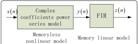
In this paper, the Hammerstein model (Figure 2), a modification of Volterra, has been used, which is given by:
y nð Þ ¼X P
k¼1
akxkð Þn
z nð Þ ¼X M−1 i¼0
hiy nð −iÞ
ð4Þ
where x(n),y(n), andz(n) denote the input signal of the memoryless nonlinear PA model, memory linear PA and
NO. 0 NO. 1 NO. 2 NO.M-1
d
. . .
Hammerstein, respectively.M is the memory depth and
Pis the order of nonlinear system.
The memory linear model uses anM−order FIR filter as description. In order to reflect its AM-AM and AM-PM characteristics simultaneously, the memoryless nonlinear model employs a complex coefficients power series model. Assume thatak=aIk+jaQk,x(n) =rejθ. So,
The functions of AM-AM and AM-PM can be given by:
From the above conclusion, power series with complex coefficients can describe the characteristics of AM-AM and AM-PM. If the PA has no memory, the output of the PA is determined only by the odd-component of the input signal. The even-component of the input signal will not affect the output of the PA, which can be expressed as:
3.2 The analysis of the transmitted multi-beam signal based on the Taylor model
After frequency mixing of two transmitted real signals, the output signals can be represented as:
s1ð Þ ¼t A1ð Þt cosðω0tþφ1ð Þt Þ
s2ð Þ ¼t A2ð Þt cosðω0tþφ2ð Þt Þ ð 8Þ
The signal input into the nonlinear PA is given by:
sinð Þ ¼t Aw1A1ð Þt cosðω0tþφ1ð Þ−t ϕw1Þ
þAw2A2ð Þt cosðω0tþφ2ð Þ−t ϕw2Þ ð 9Þ
where Aw1;Aw2 and ϕw1;ϕw2 are the amplitudes and phases of the two weight vectorsw1andw2, respectively.
A1(t),A2(t) andφ1(t),φ2(t) are the amplitudes and phases of the two signals, respectively.ω0is the carrier frequency.
Even order harmonic component, produced by PA, can be removed by filters. Therefore, the odd-order harmonic component, which cannot be removed by filters, has a great effect on input signals. According to the power series model, after the signal passes the nonlinear PA, the output signal is given by:
soutð Þ ¼t a1sinð Þ þt a3sinð Þt 3 ð10Þ
wherea1,a3is a real number.
Expanding the cubic term and removing the non-fundamental frequency component, we can get:
a3sinð Þt 3≈a3
The real signal is a double-sideband signal. To analyze conveniently, we study one side of the spectrum, and the analytic signal of output is given by:
soutðtÞ ¼a1 As1ð Þte
According to expression in (12), whether the nonlinear term is the same as the original signal is related to the input signal. Under amplitude modulation, the desired signal can be represented as:
sdesireð Þ ¼t a1 As1ð Þte
All items of a3in expression (12), which are different from previous signals, are interference signals.
sjamð Þ ¼t a3
When it is not an amplitude modulation, the cubic term contains a part of desired signal component, and the de-sired signal can be represented as:
sdesireð Þ¼t a1As1þa3
The interference signal can be represented as:
sjamð Þ ¼t a3
According to expression in (14) and (16), on the condi-tion of amplitude modulacondi-tion, the power of interference signal mainly consists of the signal which has the same weight vector with the desired signal, and the power of interference signal has the same pointing direction with the desired signal. However, on the condition of non-amplitude modulation, it is the weight vectorswH
12w2 and
wH
22w1that determining the pointing direction of interfer-ence signal power.
3.3 The analysis of the transmitted multi-beam signal based on the Hammerstein model
A complex envelope of the input signal which is the sum of two narrow-band signals can be expressed by:
x nð Þ ¼Aw1A1ð Þn e φ2(n) are the amplitudes and phases of the two signals.
r1ð Þ ¼n Aw1A1ð Þn andr2ð Þ ¼n Aw2A2ð Þn.
After the signal passes the memoryless nonlinear model, the output signal is given by
y nð Þ ¼a1x nð Þ þa3x nð Þjx nð Þj2
¼ða1þa3r2ð Þn Þx nð Þ ð
18Þ
where r2ð Þ ¼n r1ð Þn 2þr2ð Þn2þ2r1ð Þn r2ð Þn cos½φ1ð Þ−n ϕw1−φ2ð Þ þn ϕw2.
If the input signals have constant envelopes, that is r1(n) =r1 and r2(n) =r2 then:
We notice that the first and third coefficients are time-independent complexes, so they can be regarded as original signals. However, the second and fourth coeffi-cients are time-dependent complexes, which means that the information carried by the signal envelope has chan-ged. Hence, they should be considered as interferential signals. The effect of nonlinearity on the transmitted sig-nal can be measured by the power ratio of the origisig-nal signal to interference.
The output of memoryless PA model is seen as the in-put of linear FIR filter. Assume that the memory depth is 2. Then, the output signal of memory PA model can be represented as:
z nð Þ ¼h0y nð Þ þh1y nð −1Þ ð20Þ
and φ (n) are different information. Finally, Equation 10 also can be described as:
z nð Þ ¼h0
a1r1þa3r1 r21þr22
ejφ1ð Þn−ϕw1
þh0
a1r2þa3r2 r21þr22
ejφ2ð Þn−ϕw2
þh1
a1r1þa3r1 r21þr22
ejφ1ðn−1Þ−ϕw1
þh1
a1r2þa3r2r21þr22
ejφ2ðn−1Þ−ϕw2
þ2h0a3r12r2cos
φ1ð Þn−ϕw1−φ2ð Þ þn ϕw2
ejφ1ð Þn−ϕw1
þ2h1a3r12r2cos
φ1ðn−1Þ−ϕw1−φ2ðn−1Þþϕw2
ejφ1ðn−1Þ−ϕw2
þ2h0a3r22r1cos
φ1ð Þn−ϕw1−φ2ð Þ þn ϕw2
ejφ2ð Þn−ϕw2
þ2h1a3r22r1cos
φ1ðn−1Þ−ϕw1−φ2ðn−1Þþϕw2
ejφ2ðn−1Þ−ϕw2
ð21Þ
According to the expression in (21), it can be seen that the first and second signals are still original signals. However, the third and fourth signals have different phases from the original signals, and the rest of the sig-nals have become new sigsig-nals which the amplitudes vary with time. That is to say, except for the first and second signals, the others are interferential signals.
4 Simulation
Consider a 16-element array with elements uniformly spaced on the line of distance equal to half wavelength. Two transmitted beams are assumed to be transmitted at angle 30° and−20°. Several null points are set at angle−10°, 10°, and 50°. One thousand sampling points are chosen. The transmitted signals are two linear frequency modulation signals with s1ð Þ ¼t As1ejKt
2
þn1ð Þt and
s2¼As2ej 2πBtþjKt2
þn2ð Þ, wheret K=B/T. B= 10 M is
the bandwidth of the signal and T is pulse period,T=
NTs=N/fs, N= 1,000 is the sampling numbers and fs= 3.01/2 × 109Hz is the sampling frequency. n1(t) and n2 (t) are system thermal noises. The transmitted signal before it is input to PA has an SNR = 90 dB. Although the amplitudes, As1 and As2, are the same, the two sig-nals which have different carrier frequencies are orthog-onal. The first coefficient of PA is a1= 1. The first tap coefficient of FIR is h0= 1 and the memory depth is 2. The beam pattern affected by the nonlinear PA is pro-duced by a beamforming technique based on orthog-onal projection algorithm.
a1/a3is set to measure the memoryless nonlinearity of PA andh0/h1is used to measure the memory effect of PA. The effect of nonlinearity PA on the multi-beamforming at −20° can be shown by changing the two parameters.
Figure 3 and Figure 4 show AM and AM-PM variation curves versus different PA coefficients. According to these figures, it can be found that the linearity ofa3=−0.01 × (2 +j) is less thana3=−0.01 × (1 +j).
The power ratio of the original signal to the interfer-ence can show the effect of the nonlinearity of PA on the input signal. Figure 5 shows that whenh1= 10−2and the input signal power is below 7 dBm, the power ratio keeps 40 dB with different nonlinearities. It can be ex-plained that when the input signal power is small, the memory effect plays a dominant role. On the other hand, when the input signal power is 20 dBm, owing to the nonlinearity, the ratio of a3=−0.01 × (2 +j) is more thana3=−0.01 × (1 +j).
Equation 9 shows that the equation value is significant only ifa3andh1a1have the same dimension, which means
−10 −5 0 5 10 15 20 25
−15 −10 −5 0 5 10 15 20 25
the input signal power(dBm)
the output signal power(dBm)
a3=0
a3=−0.01×(1+j)
a3 = −0.01×(2+j)
we can ignore the effect of h1a3 on beamforming. In addition, the nonlinearity represents gain compression characteristics. So,a3is negative andh1is positive. Under this premise, the total power of interference can be consid-ered as a positive, when the memory effect plays a major role. The power of interference becomes weak as the mem-ory effect is reduced. On the contrary, when nonlinearity plays a key role, the total power of interference is a negative.
The power of interference increases as the memory effect is reduced. This is why the power ratio has an upward trend.
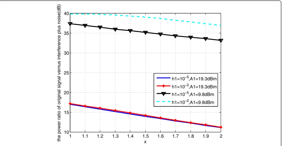
To measure the memoryless nonlinearity of PA, we as-sumed that a3=−0.01 × (x+j), h1= 10−5 and A1= 19.3 dBm, wherexis an independent variable. Figure 6 shows that when the input signal power A1 is 19.3 dBm, the power ratio of the different h1 is almost identical. However, when A1 is 9.8 dBm, the power ratio of the
−10 −5 0 5 10 15 20 25
−25 −20 −15 −10 −5 0
the input signal power(dBm)
the output signal phase(
o)
a3=0
a3=−0.01×(1+j) a3 = −0.01×(2+j)
Figure 4AM-PM conversion.
−10 −5 0 5 10 15 20 25
−10 0 10 20 30 40 50 60 70
the input signal power(dBm)
the power ratio of original signal versus interference plus noise(dB)
a3=−0.01×(1+j),h1=10−5
a3=−0.01×(1+j),h1=10−2
a3=−0.01×(2+j),h1=10−2
different h1 is different. The same conclusion can be found in Figure 6.
a3=−0.01 × (1 +j),A1= 9.8 dBm, andA1= 19.3 dBm are assumed to measure the memory effect of PA. From Figure 7, it can be seen that when the input signal power A1is 9.8 dBm,h1which is more than 10−4will affect the ra-tio. However, it hardly affects the ratio whenh1is less than 10−5. On the other hand, when the power of input signal
A1is 19.3 dBm, it is a turning point thath1is 10−2. So, it is concluded that the low power of input signal is sensitive to the memory effect. The reason for the upward trend in Figure 7 has already been explained in Figure 5.
5 Conclusion
In this paper, starting from the signal form, the output signal of PA is obtainedviathe establishment of the PA
1 1.1 1.2 1.3 1.4 1.5 1.6 1.7 1.8 1.9 2 10
15 20 25 30 35 40
x
the power ratio of original signal vernus interference plus noise(dB)
h1=10−5,A1=19.3dBm
h1=10−2,A1=19.3dBm
h1=10−5,A1=9.8dBm
h1=10−2,A1=9.8dBm
Figure 6The power ratio of original signal versus interference plus noise withx.
-80 -70 -60 -50 -40 -30 -20 -10
10 15 20 25 30 35 40
h0/h1(dB)
th
e pow
er
r
a
ti
o of
or
ig
in
al
s
ignal
v
e
rs
us
i
n
te
rf
er
enc
e pl
us
noi
s
e(
dB
)
A1=19.3dBm A1=9.8dBm
model. Then the influence of the memory effect and non-linearity of PA is presented by analyzing the composition of the final output signal. Lastly, computer simulations verify that the memory effect plays a key role, in the presence of the small power signal, while the nonlinearity plays an im-portant role in the presence of the large power signal. A de-tailed theoretical basis and reference to linearize PA is provided in this paper for other researchers. When the transmitted signals are small power signals, the memory ef-fect should gain attention in linearizing PA. However, if large power signals are transmitted, the importance of the nonlinearity of PA should be attached.
Competing interests
The authors declare that they have no competing interests.
Acknowledgements
This research was supported by Applied Basic Research Programs of Sichuan Province (No. 2013JY0004), National Natural Science Foundation of China (No. 61371184) and the Fundamental Research Funds for the Central Universities (No. ZYGX2012J018).
Received: 16 January 2014 Accepted: 24 March 2014 Published: 16 April 2014
References
1. L Ding, GT Zhou, DR Morgan, Z Ma, JS Kenney, J Kim, CR Giardina, A robust digital baseband predistorter constructed using memory polynomials. IEEE Trans. Commun.52(1), 159–165 (2004)
2. M Isaksson, D Wisell, D Ronnow, A comparative analysis of behavioral models for RF power amplifiers. IEEE Trans. Microw. Theory Tech.54(1), 348–359 (2006) 3. H Ku, JS Kenney, Behavioral modeling of nonlinear RF power amplifiers
considering memory effects. IEEE Trans. Microw. Theory Tech.51(12), 2495–2504 (2003)
4. W Bosch, G Gatti, Measurement and simulation of memory effects in predistortion linearizers. IEEE Trans. Microw. Theory Tech.37, 1885–1890 (1989) 5. JHK Vuolevi, T Rahkonen, JPA Manninen, Measurement technique for
characterizing memory effects in RF power amplifiers. IEEE Trans. Microw. Theory Tech49, 1383–1388 (2001)
6. J Kim, K Konstantinou, Digital predistortion of wideband signals based on power amplifier model with memory. Electron. Lett.37(23), 1417–1418 (2001) 7. H Ku, M Mckinley, JS Kenney, Quantifying memory effects in RF power
amplifiers. IEEE Trans. Microw. Theory Tech.50(12), 2843–2849 (2002) 8. Y Wu, Y Liu, The analysis of the effect of high power amplifier and
bandwidth to the constant envelop guidance signal. J Telemetry. Tracking. Command.32(3), 14–20 (2011)
9. EC Kohls, EP Ekelman, AI Zaghloul, FT Assal, Intermodulation and bit-error ratio performance of a Ku-band multibeam high-power phased array, in
Proceedings of the IEEE International Symposium on Antennas and Propagation,
vol. 3 (IEEE, Piscataway, 1995), pp. 1404–1408
10. C Hemmi, Pattern characteristics of harmonic and intermodulation products in broadband active transmit arrays. IEEE Trans. Antennas Propag.50(6), 858–865 (2002)
11. KJ Maalouf, E Lier, Theoretical and experimental study of interference in multibeam active phased array transmit antenna for satellite communications. IEEE Trans. Antennas Propag.52(2), 587–592 (2004) 12. EC Real, DP Charette, Non-linear amplifier effects in transmit beamforming
arrays, inProceedings of the IEEE International Conference on Acoustics Speech
Signal Processing, vol. 5 (IEEE, Piscataway, 1995), pp. 3635–3638
doi:10.1186/1687-6180-2014-52
Cite this article as:Liet al.:The analysis of the performance of multi-beamforming in memory nonlinear power amplifier.EURASIP Journal on Advances in Signal Processing20142014:52.
Submit your manuscript to a
journal and benefi t from:
7Convenient online submission
7Rigorous peer review
7Immediate publication on acceptance
7Open access: articles freely available online
7High visibility within the fi eld
7Retaining the copyright to your article