A Retrodirective Array with Reduced Surface Waves for Wireless
Power Transfer Applications
Mohammad Fairouz and Mohammad Saed*
Abstract—A one-dimensional, dual frequency, active retrodirective array is proposed for wireless power transfer applications. Microstrip circular patch antennas with four shorting pins are used as array elements to suppress surface waves. The proposed design eliminates undesired coupling between array elements due to surface waves present in conventional microstrip antenna arrays in order to improve array performance. The antenna array uses circularly polarized microstrip elements with higher gain than conventional microstrip antennas. The proposed retrodirective array operates at 2.4 GHz for the interrogating signal and 5.8 GHz for the retransmitted signal, using up-converting mixers. The beam scanning inherent in retrodirective arrays ensures a constant power level available to the charging devices, regardless of their location within an angular sector over which retrodirectivity is achieved. A two-element experimental prototype provided uniform power density within a 60◦ angular sector. The Design procedure, simulation results and experimental measurements are presented.
1. INTRODUCTION
Wireless power transfer (WPT) is a process to transfer the electrical energy from power source to an electrical load without using wires [1, 2]. The idea of wireless power transfer came from Nikola Tesla at the turn of the twentieth century when he made a tower to transfer power without wires [3]. The most common techniques used in (WPT) utilize inductive coupling to transfer power wirelessly. These techniques are based on magnetic field induction between two coils placed in close proximity to each other [4]. In [5], ceramic dielectric resonators were used instead of conventional resonant coils to transfer power wirelessly. Ceramic dielectric resonators have very high unloaded Q factors; the resonators are typically covered with a metal surrounding to reduce the radiation loss [6]. In [7], another induction coupling method is described where a plastic sheet containing an array of coils is used for charging devices placed on it. An array of MEMS and an array of FETs are used to detect the location of the device and switch on the coil closest to it. Wireless power transfer methods based on induction techniques, resonant and non-resonant, are only useful for transferring power over very short distances (no more than a meter or two with the resonant coil methods). A laser technique to transfer power wirelessly was introduced in [8, 9]. A major disadvantage of the laser technique is the danger of using a high intensity laser beam, need for precision and clear line of sight with no obstructions. Also, efficiency suffers due to the low conversion efficiency from optical to electrical energies [9]. Wireless power transfer using microwaves overcomes the distance limitations encountered in resonant and induction coupling methods, and avoids the shortcomings of the laser techniques. A monopole with a corner reflector antenna was used for wireless power transfer in [10]. In [11], expected performance of Van Atta retrodirective arrays was investigated theoretically assuming dipole antennas as array elements, however, there was no experimental implementation.
A retrodirective array is a smart antenna that scans its main beam to point to the direction of a transmitter without prior knowledge of the transmitter’s location. Recently, retrodirective arrays were
Received 28 October 2014, Accepted 30 December 2014, Scheduled 21 January 2015
* Corresponding author: Mohammad Saed ([email protected]).
investigated for use in several applications, such as radar and military communication systems [12]. A basic implementation of a retrodirective antenna is the corner reflector. Another simple passive implementation is the Van Atta retrodirective array [13]. A popular more flexible active implementation uses mixers to realize phase conjugation [14]. In single frequency retrodirective array, the input radio frequency (RF) signal is mixed with a local oscillator (LO) operating at a frequency equal to twice the RF signal frequency. Therefore, the lower side band has the same frequency as the input signal (RF) signal with a conjugated phase [15]. Another configuration of a retrodirective array is a dual frequency implementation that employs heterodyne techniques with phase detection and phase shifters [16, 17]. Dual frequency retrodirective arrays can be used for bidirectional communications transmission and reception [18, 19].
In this work, we introduce a microwave wireless power transfer method using a novel dual frequency retrodirective antenna array to increase efficiency. Retrodirective arrays have the potential for efficient wireless power transfer applications due to their inherent ability to point their beam towards a transmitter without prior knowledge of the transmitter’s location. The proposed design uses a novel circularly polarized microstrip antenna array where surface waves are suppressed to increase efficiency and gain, and minimize mutual coupling between array elements. Conventional microstrip antennas printed on dielectric substrates suffer from excitation of undesired surface waves [20]. In addition to lowering the antenna efficiency and distorting radiation patterns, surface waves increase mutual coupling between the elements of the antenna array, which can lead to scan blindness. This can be a serious problem in retrodirective arrays since the antenna beam is scanned to point toward the interrogating signal. In [21, 22], a design is proposed to reduce surface waves based on a principle that a ring of a magnetic current in a substrate will not excite the surface wave if the radius of the ring is equal to a particular critical value. In another design [23], the portion of the substrate underneath the microstrip patch was replaced with another material which has lower dielectric constant. In [24, 25] a circular microstrip patch antenna with shorting pins to reduce the excitation of surface waves was investigated numerically. However, the simulation results presented in [25] focused on an isolated element and lacked experimental verification, and array performance was not considered. In [26], a linearly polarized single patch with a shorting pin, and a portion of the dielectric underneath the patch removed, was investigated.
In this paper, microstrip circular patch antennas with four shorting pins are used as the array elements in order to reduce the excitation of the surface waves in the proposed dual frequency retrodirective array. This will minimize the mutual coupling between the array elements, improving the overall array performance by having higher gain, better radiation pattern, and better beam scanning (avoiding scan blindness). To obtain circular polarization, a narrow slot with a single feed is used. To obtain circular polarization with the narrow slot, it must be oriented at 45◦ to the feed axis and its length must be optimized in order to excite two orthogonal modes that have equal amplitudes and are 90◦ out of phase. Circular polarization is chosen for the wireless power transfer application to ensure devices receive the transmitted signal (the charging signal) regardless of their own antenna orientation. For wireless devices, the device’s own data signal (e.g., WIFI signal) can be used as the interrogating signal which the retrodirective array can use to direct its transmitted beam towards the wireless device for charging. In this work, we chose 2.4 GHz as the frequency of the interrogating signal and 5.8 GHz as the frequency of the transmitted signal used for power transfer. The goal is to have a system with the ability to scan the beam within a 60-degree sector, in order to maximize the power received by the devices within that sector.
2. PROPOSED SYSTEM
Transmitting Antenna Receiving Antenna
LO 3.4 GHz
Amplifier Mixer
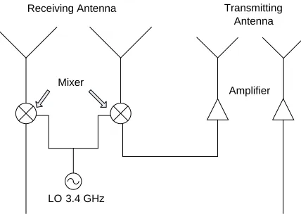
Figure 1. Block diagram of a one-dimensional dual frequency retrodirective array.
the RF and IF frequencies), and therefore, the down-conversion results in phase conjugation of the signal needed for retrodirectivity. In our design, the mixers are used as up-converters, and therefore do not produce phase conjugation. The advantage is that a lower LO frequency is needed, equal to the difference between the RF and IF frequencies.
To explain the lack of phase conjugation in up-converting mixers, the expression for the output signal of a mixer can be written as:
VIF =VRFcos (ωRFt+θn)VLOcos (ωLOt)
= 1
2VRFVLO[cos ((ωLO −ωRF)t−θn) + cos ((ωLO +ωRF)t+θn)] (1) where IF is outgoing signal, RF is incoming radiofrequency signal, LO is local oscillator and θn is the phase angle of thenth element. The phase of the down-converted term (the (ωLO−ωRF) term) is −θn
(the phase is conjugated) while the phase of the up-converted term (the (ωLO +ωRF) term) is +θn
(the phase is not conjugated).). Retrodirectivity in our design is achieved by properly connecting the receiving and transmitting arrays to scan the transmitter beam in the direction of the interrogating signal, as in a Van-Atta array. Since the transmit and receive frequencies are different, it is very important to properly choose the transmission line lengths in the feed network, and transmit and receive array element spacing to avoid beam pointing errors. The transmission lines between the receiving array elements and the mixers must be equal, and the transmission line connecting the mixers to the transmitting array elements must also be equal. This ensures that the phase shifts due to the connecting lines are equal for each transmit-receive antenna pair. Also, the electrical distance between the receiving array elements must be equal to the electrical distance between the transmitting array elements. In other words, if the receiving array elements are separated by a half wavelength (at the receiving frequency), the transmitting array elements must also be separated by a half wavelength (at the transmitting frequency). Ensuring proper line lengths and array element spacing as described guarantees the correct phasing of the transmitting array elements in order to properly redirect the beam towards the interrogating signal.
An amplifier is used to amplify the transmitted signal to the desired power level. To demonstrate the design concept, we used two-element arrays for the transmitting and receiving antennas. We used the mixer ZX05-U63+, the voltage control oscillator (VCO) ZX95-3760+, and the amplifier ZX60-V63+, all from Mini-circuits, Inc. A Wilkinson power divider is needed in this design to split the VCO signal and to provide isolation between the two output ports [27]. The divider was fabricated on RT/Duroid 6010 dielectric substrate with dielectric constant of 10.2 and thickness of 1.27 mm.
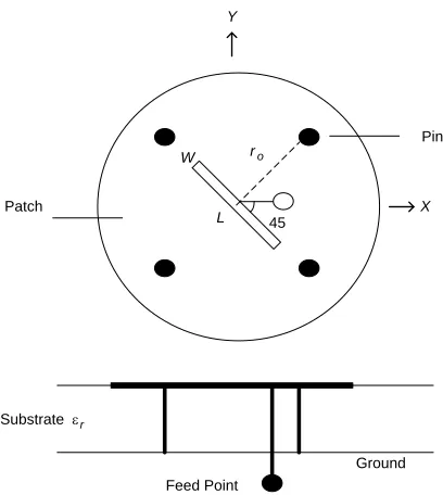
The transmitting array of the retrodirective system uses a circularly polarized microstrip patch, shown in Figure 2, as the array element. The patch is designed to suppress surface waves by incorporating four shorting pins.
A conventional circular patch antenna resonates in the dominant TM110 mode at a frequency that
satisfies the following equation:
Substrate εr
ro
45
Feed Point
L W
Pin
Patch
Ground
X Y
Figure 2. A circular patch antenna of radius awith four shorting pins of radii b.
Figure 3. The TM1 mode normalized frequency for
4-pin loaded circular patch.
where “a” is the radius of the circular patch,x11the first root of the derivative of the first order Bessel
function of the first kind, andk= 2λπ the wave number in the substrate medium. In order to eliminate surface waves due to the lowest mode, the following condition must be satisfied [25]:
k0a= 1.8412 (3)
where k0 = 2λπ0 is the wave number in air. The conditions given in Equations (1) and (2) cannot be
satisfied simultaneously in a conventional microstrip patch with a non-air substrate. A method to satisfy both conditions was investigated numerically by adding shorting pins to the circular patch antenna. The following equation, for the normalized resonant frequency kaof a circular patch with four pins loaded patch was derived in [25]:
Y0(kb)+Y0(kd1)±Y0(kd2)±Y0(kd3)−8
∞
n=even/odd
xncos2
αJn
k(r0−b)Jn(kr0)Yn(ka)
Jn (ka)
= 0 (4)
where r0 is the pins’ radial position; b is the radius of the pins; Jn and Yn are the Bessel functions of
the first and the second kinds, respectively; α is the angle between thex-axis and the pins (the feeding probe is located on the x-axis); xn = 1(n ≥1) for even mode andxn= 1/2 for odd mode;d1, d2 and
d3 are the distances to the pin at φ= +α from the other three pins, given by d1 = 2r0sinα,d2 = 2r0
and d3 = 2r0cosα. The angleα is chosen equal to 45◦ to maintain symmetry.
Given a desired shorting pin radius b and position r0, Equation (4) can be solved numerically for
the required value of ka to suppress the surface waves for the first order mode TM1. A graph for ka
versus pin position r0/a can then plotted, as shown in Figure 3 for pin radius b/a = 0.03, 0.04, and
0.055. Then, the curves can be used to determine the pins’ location for a desired substrate’s dielectric constant.
3. SIMULATION AND MEASUREMENT RESULTS
wavenumber k0 (not k) is used to determine the patch radius. This fact results in higher antenna
gain for our design when compared to conventional microstrip patches. The required value ofka for our substrate is given by:
ka=k0
√
εra= 2.81 (5)
Using this value of ka in Figure 3, the required shorting pin position for a pin radius b/a = 0.055 is r0/a= 0.72. To obtain circular polarization, a diagonal narrow slot at the center of the patch was used.
The design for a single patch was optimized in ANSYS HFSS resulting in the following dimensions: slot length L = 10 mm, slot width W = 1 mm, a = 15.15 mm, r0 = 10.9 mm and b = 0.83 mm.
The antenna was fabricated using a milling machine. The simulation and measurement results for the reflection coefficient (|S11|dB) are shown in Figure 4. The measured return loss at the resonant frequency
(5.76 GHz) is more than 20 dB (it is 18 dB at 5.8 GHz) and the measured 10-dB bandwidth is 240 MHz (5.65 GHz–5.89 GHz). The bandwidth is more than 4%, which is better than a conventional patch (less than 2%).
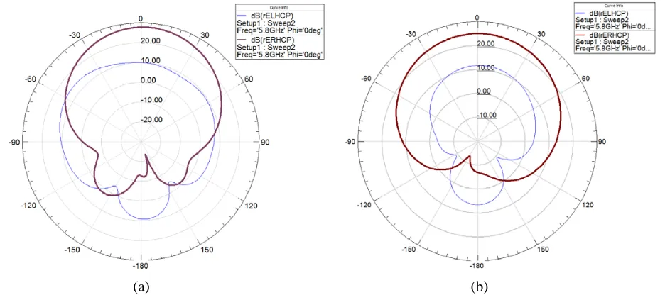
The simulated radiation patterns of the patch with shorting pins and a conventional patch at 5.8 GHz are shown in Figures 5(a) and (b). The radiation pattern for the patch with shorting pins has a narrower main beam and shows significantly reduced radiation in the plane of the substrate (about
Figure 4. Reflection coefficient (S11) in dB versus frequency in GHz for proposed design of circular
patch antenna with four shorting pins at 5.8 GHz (experiment in sold line and simulation in dot line).
(a) (b)
Spectrum analyzer 5.8 GHz
Interrogating signal
Retransmitted signal Signal generator
2.4 GHz
Transmitting Antenna Receiving
Antenna
LO 3.4 GHz
Amplifier Mixer
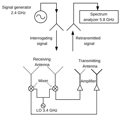
Figure 6. Monostatic setup test for retrodirec-tive array.
Figure 7. Monostatic radiation patterns for the retrodirective array (solid curve) and the normal array (dashed curve).
23 dB below broadside) compared to the conventional patch (about 11.7 dB below broadside). The computed gain and front to back ratio for the patch with shorting pins are also significantly better. Its gain is 7.6 dB, and the front to back ratio is 39 dB, versus 5.4 dB gain and 31 dB front to back ratio for the conventional patch. These features make this antenna an excellent element in antenna arrays to reduce mutual coupling and improve overall gain and efficiency.
The single patch was used to design the two-element, circularly polarized transmitting array. A circularly polarized probe-fed conventional microstrip circular patch operating at 2.4 GHz was used as the array element for the receiving array.
The complete retrodirective array was constructed using the transmitting array, receiving array, and feed network, consisting of the VCO, mixers, Wilkinson’s power divider, and amplifiers, as shown in Figure 1. A monostatic setup was used to test the performance of the retrodirective system in Figure 6. A fixed 2.4 GHz transmitter and a 5.8 GHz receiving antenna were collocated, and the retrodirective system was mounted on a rotational stage. The radiation pattern (recorded by the fixed 5.8 GHz receiver) was measured to test the system’s capability in steering its beam toward the transmitter. The measurement was repeated using a normal non-retrodirective array.
The measured radiation patterns for both cases are shown in Figure 7 (the retrodirective array pattern is the solid curve and the normal antenna arrays is the dotted curve. The figure clearly shows that the received power for the retrodirective array is relatively flat between −30◦ to 30◦ (60◦ sector) while the received power starts to drop beyond 5◦ for the normal non-retrodirective antenna array.
4. CONCLUSION
far more efficient power delivery than antennas with a fixed beam to devices without prior knowledge of their location.
REFERENCES
1. Brown, W. C., “The history of power transmission by radio waves,” IEEE Transactions on Microwave Theory and Techniques, Vol. 32, No. 9, 1230–1242, Sep. 1984.
2. O’Brien, K., R. Teichmann, and H. Gueldner, “Magnetic field generation in an inductively coupled radio-frequency power transmission system,” 37th IEEE Power Electronics Specialists Conference, PESC’ 06, 1–7, Jun. 18–22, 2006.
3. Tesla, N., “The transmission of electric energy without wires,” The 13th Anniversary Number of the Electrical World and Engineer, 1904.
4. Tseng, R., “Method and apparatus for wireless power transmission,” US Patent Application No. 11/901158, 2007.
5. Nishikawa, K. and T. Ishizaki, “Microwave-band wireless power transfer system using ceramic dielectric resonators,”2013 IEEE Wireless Power Transfer (WPT), 175–178, May 15–16, 2013. 6. Ishizaki, T. and K. Nishikawa, “Wireless power beam device using microwave power transfer,”
IEEE Wireless Power Transfer Conference (WPTC), 36–39, IEEE, 2014.
7. Takamiya, M., T. Sekitani, Y. Miyamoto, Y. Noguchi, H. Kawaguchi, T. Someya, and T. Sakurai, “Design solutions for a multi-object wireless power transmission sheet based on plastic switches,”
IEEE International Solid-State Circuits Conference, Digest of Technical Papers, 362–609, 2007. 8. Rangelov, A. A., H. Suchowski, Y. Silberberg, and N. V. Vitanov, “Wireless adiabatic power
transfer,”Annals Phys., Vol. 326, 626–633, 2011.
9. Vandervoorde, G. and R. Puers, “Wireless energy transfer for standalone systems: A comparison between low and high power applicability,” Sensors and Actuators, Vol. 92, 305–311, Nov. 2000. 10. Abbasi, M. I., S. Atif Adnan, M. Amin, and F. Kamran, “Wireless power transfer using microwaves
at 2.45 GHz ISM band,” 2009 6th International Bhurban Conference on Applied Sciences and Technology (IBCAST), 99–102, IEEE, 2009.
11. Li, Y. and V. Jandhyala, “Design of retrodirective antenna arrays for short-range wireless power transmission,” IEEE Transactions on Antennas and Propagation, Vol. 60, No. 1, 206–211, 2012. 12. Fusco, V. and N. Buchanan, “Analysis and characterization of PLL-based retrodirective array,”
IEEE Transactions on Microwave Theory and Techniques, Vol. 53, No. 2, 730–738, 2005.
13. Guo, Y. C., X. W. Shi, and L. Chen, “Retrodirective array technology,” Progress In Electromagnetics Research B, Vol. 5, 153–167, 2008.
14. Pon, C. Y., “Retrodirective array using the heterodyne technique,”IEEE Transactions on Antennas and Propagation, Vol. 12, No. 2, 176–180, 1964.
15. Miyamoto, R. Y. and T. Itoh, “Retrodirective arrays for wireless communications,” IEEE Microwave Magazine, Vol. 3, No. 1, 71–79, 2001.
16. Rodenbeck, C., M. Li, and K. Chang, “A phased-array architecture for retrodirective microwave power transmission from the space solar power satellite,” IEEE MTT-S International Microwave Symposium Digest, Vol. 3, 1679–1682, Jun. 2004.
17. Shiroma, G. S., R. Y. Miyamoto, and W. A. Shiroma, “A full-duplex dual-frequency self-steering array using phase detection and phase shifting,” IEEE Transactions on Microwave Theory and Techniques, Vol. 54, No. 1, 128–134, Jan. 2006.
18. Chen, L., X. W. Shi, T. L. Zhang, C. Y. Cui, and H. J. Lin, “Design of a dual-frequency retrodirective array,” IEEE Antennas and Wireless Propagation Letters, Vol. 9, 478–480, 2010. 19. Chen, L., T. L. Zhang, S. F. Liu, and X. W. Shi, “A bidirectional dual-frequency retrodirective array
20. Zhu, Y., Y. Xie, Z. Lie, and T. Dang, “A novel method of mutual coupling matching for array antenna design,” Journal of Electromagnetic Waves and Applications, Vol. 21, No. 8, 1013–1014, 2007.
21. Jackson, D. R., J. T. Williams, A. K. Bhattacharyya, R. L. Smith, S. J. Buchheit, and S. A. Long, “Microstrip patch that do not excite surface waves,” IEEE Transactions on Antennas and Propagation, Vol. 41, No. 8, 1026–1037, Aug. 1993.
22. Bassilio, L. I., J. T. Williams, D. R. Jackson, and M. A. Khayat, “A comparative study for a new GPS reduced surface wave antenna,” IEEE Antennas and Wireless Propagation Letters, Vol. 4, 233–236, 2005.
23. Mehrotra, A. R., D. R. Jackson, J. T. Williams, and S. A. Long, “An annular-ring reduced surface wave microstrip antenna,” IEEE Antennas and Propagation Society International Symposium, Vol. 2, 810–813, Aug. 1999.
24. Al-Ajmi, A. R. and S. F. Mahmoud, “A single-feed circularly-polarized patch antenna for reduced surface wave applications,”Microwave and Optical Technology Letters, Vol. 51, No. 11, 2675–2679, 2009.
25. Mahmoud, S. F. and A. R. Al-Ajmi, “A novel microstrip patch antenna with reduced surface wave excitation,” Progress In Electromagnetics Research, Vol. 86, 71–86, 2008.