Design and Simulation of Centrifugal Pump Using
Composite Materials
Sudhakar Reddy & G.Naresh Babu
1M.Tech, Department of Thermal Engineering, Siddhartha institute of Technology &Science
2
Assistant Professor, Department of Thermal Engineering, Siddhartha institute of Technology &Science
Abstract - Centrifugal pumps are used to
transport liquids/fluids by the conversion of
the rotational kinetic energy to the hydro
dynamics energy of the liquid flow. The
rotational energy typically comes from an
engine or electric motor or turbine. In the
typical simple case, the fluid enters the
pump impeller along or near to the rotating
axis and is accelerated by the impeller,
flowing radially outward into a diffuser or
volute chamber (casing), from where it exits.
The Contemporary impellers blades in
Centrifugal pumps are used in industrial
applications are made up of Aluminium or
Steel. It is proposed to design a centrifugal
pump using Computer Aided Design (CAD)
software with various metal alloys and
NonMetallic composite materials, analyze
its strength and deformation using
simulation software. In order to evaluate the
effectiveness of Metal Alloys and
NonMetallic composites. The present work
aim is to change the material and
performing the different analysis like Static,
Dynamic, Analysis to find the best material
to decrease the weight and increase its
efficiency by using the software SOLID
WORKS (2014 Premium Version). This also
involves the method of manufacturing
process to realize the Blower using
Non-Metallic composite material.
Key Words: Centrifugal pump, Computer
Aided Design (CAD), Metal Alloys,
Non-Metallic Composite Materials,
SOLIDWORKS, Simulation Analysis.
1. INTRODUCTION
The application of fluid machinery has
spread its wings in all aspects of human life.
The usage of pumps extends to domestic
services, commercial and agricultural
services, municipal water/wastewater
services, and industrial services such as food
processing. Pumps are also used in
chemical, petrochemical, pharmaceutical
and mechanical industries. This chapter
deals with the classification of the pumps,
their applications and their operating
principles.
Classification
In general, pumps are classified into Positive
Displacement Pumps and Centrifugal Pumps
based on their working principles
Positive Displacement Pumps
A positive displacement pump operates by
alternately filling a cavity and then
displacing a given volume of liquid. The
positive displacement pump delivers a
constant volume of liquid against varying
discharge pressure or head.
Single Rotor Pumps
Vane - The vane/vanes may be blades,
buckets, rollers or slippers which cooperate
with a dam to draw fluid into and out of the
pump chamber.
Piston - Fluid is drawn in and out of the
pump chamber by a piston/pistons
reciprocating within a cylinder /cylinders
and operating port valves.
Flexible Member - Pumping and sealing
depend on the elasticity of a flexible
member/members which may be a tube,
vane or a liner.
Single Screw - Fluid is carried between rotor
screw threads as they mesh with internal
threads on the stator.
Progressing Cavity - Fluid is carried
between a rotor and a flexible stator
Multiple Rotor Pumps
Gear - Fluid is carried between gear teeth
and is expelled by the meshing of the gears
which provide continuous sealing between
the pump inlet and outlet.
Lobe - Fluid is carried between rotor lobes
which provide continuous sealing between
the pump inlet and outlet.
Circumferential Piston - Fluid is carried in
spaces between piston surfaces not requiring
contacts between rotor surfaces.
Multiple Screw - Fluid is carried between
rotor screw threads as they mesh.
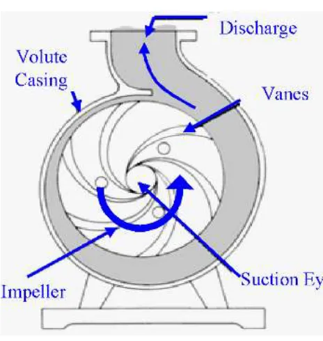
Centrifugal Pumps
Centrifugal pumps can be classified based on
the manner in which fluid flows through the
pump. The manner in which fluid flows through
the pump is determined by the design of the
pump casing and the impeller. The three types
of flow through a centrifugal pump are radial
Fig 1: Centrifugal Pump
Radial Flow
In a radial flow pump, the liquid enters at
the center of the impeller and it is directed
out along the impeller blades in the direction
at right angles to the shaft of the pump in
which the pressure is developed wholly by
centrifugal force. When the head
requirement is more, radial flow pumps are
preferred.
Axial Flow
In an axial flow pump, the impeller pushes
the liquid in the direction parallel to the
pump shaft in which the pressure is
developed by the propelling or lifting action
of the vanes of the impeller on the liquid.
Axial flow pumps are sometimes called
propeller pumps because they operate
essentially as the propeller of a boat does.
When more flow rate is required, axial flow
type pumps are preferred.
2. LITERATURE REVIEW
Lazarkiewicz Stepen (1965) has explained
the procedure to calculate the dimensions of
the impeller and has also discussed various
methods for determining the shape of the
impeller blades, which are referred to by the
designers. The effects of the individual
parameters that influence the performance of
the impeller were studied by the authors
Lobanoff (1985) and Stepanoff (1948)
Van Esch (1997) in his thesis has shown that
the flow in hydraulic pumps of the radial
and mixed flow type, operating at conditions
not too far from design point, can be
considered as an incompressible potential
flow, where the influence of viscosity is
restricted to thin boundary layers, wakes and
mixing areas. He also concluded that the
design of hydraulic turbo machines has
reached the stage where improvements can
be achieved only through a detailed
understanding of the internal flow. The
impeller is complex, involving streamline
curvature, system rotation, separation and
turbulence effects.
Pedersen et al (2003) has done an exhaustive
study to visualize the flow in the centrifugal
pump impeller and his research outcome
provides a detailed instantaneous data of the
impeller flow field in the rotating passage of
a centrifugal pump impeller.
Lazarkiewicz Stepen (1965) has explained
the procedure to calculate the dimensions of
the impeller and has also discussed various
methods for determining the shape of the
impeller blades, which are referred to by the
designers. The effects of the individual
parameters that influence the performance of
the impeller were studied by the authors
Lobanoff (1985) and Stepanoff (1948).
Frost and Nilsen proposed a simple model for estimating the contribution of the volute to the shut-off head of a centrifugal pump or fan. The model is based on an assumed linear distribution of tangential velocity in the plane of the cutwater, which satisfies approximately the continuity condition of zero net flow into the outlet duct. The contribution of the impeller is assumed to be that given by a solid body rotation at the angular velocity of the pump from the bore of the inlet duct to the impeller tip. The simple radial equilibrium equation is then
used to calculate the static head rise in both the impeller and volute. The resultant prediction of shut-off head has been compared to test data on various pump series made available by courtesy of two European manufacturers. In all of the series, the impeller diameter has been varied between 100 and 90 to 80 percent of its design value and has been tested in the designed volute. Since a review of the available literature did not show any previous work of a fully consistent nature on this topic, the proposed model as described in detail is offered as a fairly accurate prediction technique for design purposes.
OBJECTIVES OF THE PROPOSED
WORK
The aim of this thesis is to propose a
computational tool for hydrodynamic design
of centrifugal pump impeller.
The objective of this work is to
• Optimize the impeller design,
Static and dynamic analysis on
centrifugal pump impeller balde is
carried out to evaluate performance at
different load conditions
• Validate the design by experiment,
with different types composite
materials
3. METHODOLOGY
Modelling
MATHEMATICAL CALCULATION FOR THE CASE STUDY
1.
Calculate pump specific speed
N s 1450* 1000/ 3600
48.07460RPM
403 / 4
2.
Calculate the input and output
power
Po 1000* 9.806* 40 * 0.2778109kW
Ps 109/ 0.86126.7kW say 127kW
3- Calculate input torque to pump
T=127000*60/2*3.14*1450 =837 N.m
2d drawing of centrifugal pimp
Centrifugal pump Solidworks CAD
Model
MATERIALS
Aluminium alloy 6061
Density 2.7 g/cm³
Tensile strength 124–290 MPa
Melting
Temperature
585 °C
Thermal
conductivity
151–202 W/(m·K)
E-Glass / Epoxy
Density 1.90 g/cm³
Tensile strength 490 MPa
Melting
Temperature
177 °C
Thermal
conductivity
0.15-0.25 W/(m·K)
Testing the performance of a pump using conventional and experimental method is time consuming and costly. It takes a long time to approve a design, if we make multiple proto type and then test each of them. Instead, simulation is used to find the performance of an impeller and casing using Computational Fluid Dynamics software. Once the flow pattern and performance are satisfactory, then we can go for one or two types to validate the simulation results.
different speeds with varying operating conditions. Then the simulation results are compared with the experimental results for the same operating conditions to confirm the suitability of this approach.
4. RESULTS AND DISCUSSION
Simulation Results
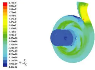
The results of the flow analysis can be viewed using plots or through surface integrals as shown in Figures 4.1 to 4.6. Surface integrals provides the required value at the given boundary condition. Plots give a graphical view of the results and they are of two types, namely, contour and vector plots. Contour plots show the constant magnitude for a selected variable (isotherms, isobars etc.). Vector plot is used to give the direction in which the flow occurs.
From Figures, it is inferred that there is a uniform distribution of pressure and velocity around the impeller in the volute casing for the maximum efficiency condition over the full open condition. The difference in the flow pattern is the cause of the radial and axial imbalances.rom, it is inferred that a highly non-uniform distribution of pressure is observed around the impeller in the volute casing, but it is less when compared to that
of 2300 rpm. As a result, the impeller is subjected to some static radial thrust.
Figure 3: Static pressure and velocity distribution for 2300 rpm for Aluminium
alloy 6061
Figure 4: Static pressure and velocity distribution for 2300 rpm for
Figure 5: Static pressure and velocity distribution for 2880 rpm for
E-Glass / Epoxy
5.
CONCLUSION Modelling and simulation of centrifugal
pump impeller has done using Solid Works software.
After observing the CFD analysis values
we can conclude that e-epoxy has the better performance is given compared to the Aluminium alloy E-glass/Epoxy material is non metallic component so, the chattering noise will be low compared to other materials during the functioning process.
For manufacturing the centrifugal pump
impeller we can proceed with Epoxy/E-glass material because it has high performance and ot will give good
efficient capa and reasonable
manufacturing cost.
REFERENCES
[1]. E.C. Bacharoudis, A.E. Filios, M.D.
Mentzos and D.P. Margaris
(2008),”Parametric study of centrifugal pump by varying the outlet blade angle”, The open mechanical engineering journal, 2008, 75-83.
[2]. LIU Houlin, WANG Yong, YUAN
Shouqi, TAN Minggao, and WANG Kai (2010),”Effects of blade number of
characteristic of centrifugal pump
”,Chinese journal of mechanical
engineering,2010.
[3]. B.Mohan, B.E. Kumar, (2014),
“Structural Analysis on Impeller of an Axial Flow Compressor using Fem”,
International Journal of Engineering
Research & Technology ISSN: 2278-0181 Vol. 3 Issue 10.
[4]. S.Rajendran and
Dr.K.Purushothaman, (2012), “Analysis of a centrifugal pump impeller using ANSYS-CFX”, International Journal of Engineering Research & Technology, Vol 1 Issue 3.
[5]. A Syam Prasad, BVVV
Lakshmipathi Rao, A Babji, Dr.P Kumar Babu, (2013), “Static and Dynamic Analysis of a Centrifugal Pump Impeller”, International Journal of Scientific & Engineering Research, Volume 4, Issue 10.
[6]. Neelambika, Veerbhadrappa (2014)
“CFD analysis of mixed flow impeller”,
International journal of research
engineering and technology.
[7]. Sambhrant Srivastavaa, Apurba
Kumar Roy and Kaushik Kumar, (2014) “Design of a mixed flow pump impeller and its validation using FEM analysis”, Science Direct, Procedia Technology 14, PN 181 – 187.
[8]. Santosh Shukla, Apurba Kumar Roy
Selection for blades of Mixed Flow Pump Impeller Using ANSYS”, Science Direct, Materials Today: Proceedings 2, 2022 – 2029.
[9]. Basawaraj, H.Hasu (2016), “A study
analysis on centrifugal pump impeller guide vane with fem approach by using different material”, IJES 2016 Volume 2016 Issue 8
[10]. S.Rajendran and
Dr.K.Purushothaman, “Analysis of a centrifugal pump impeller using ANSYS-CFX,” International Journal of Engineering Research & Technology, Vol. 1, Issue 3, 2012.
[11]. S R Shah, S V Jain and V J Lakhera,
“CFD based flow analysis of centrifugal pump,” Proceedings of the 37th National & 4th International Conference on Fluid Mechanics and Fluid Power, IIT Madras, Chennai, 2010.
[12]. P.UshaShriansC.Syamsundar,
“computational analysis on performance of a centrifugal pump impeller,” Proceedings of the 37th National & 4th International Conference on Fluid Mechanics and Fluid Power, IIT Madras, Chennai, 2010.
[13]. E.C. Bacharoudis, A.E. Filios, M.D.
Mentzos and D.P. Margaris, “Parametric Study of a Centrifugal Pump Impeller by
Varying the Outlet Blade Angle,” The Open Mechanical Engineering Journal,
[14]. Marco Antonio Rodrigues Cunh and
Helcio Francisco Villa Nova, “Cavitation modelling of a centrifugal pump impeller,” 22nd International Congress of Mechanical Engineering, Ribeirao Petro, Sao Paulo, Brazil, 2013.
[15].Mohammed Khudhair Abbas,
“cavitation in centrifugal pumps,” Diyala Journal of Engineering Sciences, pp. 170-180, 2010.
[16].AbdulkadirAman, SileshiKore and
Edessa Dribssa, “Flow simulation and performance prediction of centrifugal pumps using cfd-tool,” Journal of EEA, Vol. 28, 2011.
[17].Erik Dick, Jan Vierendeels, Sven
Serbruyns and John VandeVoorde,
“Performance prediction of centrifugal pumps with cfd-tools,” Task Quarterly 5, no 4, 579–594, 2001.
[18]. S. C. Chaudhari, C. O. Yadav and A.
B. Damo, “A comparative study of mix
flow pump impeller cfd analysis and
experimental data of submersible pump,”
International Journal of Research in
Engineering & Technology, Vol. 1, Issue 3,