Design and Performance Analysis of Double-Suction
Centrifugal Pump
Nyi Nyi*, Aung Ko**, Cho Cho Khaing**
* Faculty of Mechanical Precision Engineering, University of Technology (Yadanarpon Cyber City), Myanmar **Faculty of Mechanical Precision Engineering, University of Technology (Yadanarpon Cyber City), Myanmar
**Department of Mechanical Engineering, Technological University (Mandalay), Myanmar
DOI: 10.29322/IJSRP.9.08.2019.p92129
http://dx.doi.org/10.29322/IJSRP.9.08.2019.p92129
Abstract- This paper presents the detail design of impeller and volute casing for double-suction centrifugal pump. The designed pump can develop a head of 150 ft (46 m) and deliver 335 ft3/min or 2500 gal/min (9.48 m3/min) of clean and cold water at the speed of 1760 rpm. The designed impeller has 7.32 in (19 cm) inlet diameter, 13.5 in (34 cm) outlet diameter, 13˚ inlet vane angle and 20˚ outlet vane angle. The number of vanes is 7. The inlet width and outlet width are 1.75 in (4 cm) and 1.98 in (5 cm) respectively. The discharge diameter is 6 in (15 cm) to operate the designed head and capacity. Moreover, the performance analysis of designed pump is also presented by considering on the various losses. The predicted maximum efficiency takes place at nearly designed head and capacity. The maximum efficiency is nearly 80.14% and the expected designed efficiency of designed pump is 80%. So, predicted and designed efficiencies are not large difference and the designed efficiency has a satisfactory value. The designed double-suction centrifugal pump can fulfil the requirements of agricultural process.
Index Terms- Double-suction centrifugal pump, head, flow rate, speed, performance characteristics
.
I. INTRODUCTION
umping may be defined as the addition of energy to a fluid to move it from one point to another or to raise it to the required height. The energy given to the pump case forces the fluid to do work flowing through the pipes rising to the higher level. The input power of the pump is mechanical energy of the drive shaft driven the prime mover such as electric motor or small engine and the output energy is the hydraulic. In industries, throughout the world, pumps play in a major role. Pumps are widely used for irrigation and are most common where pumping from surface water supplies such as river, lakes and streams and rising water to a higher level. Moreover, they are widely used in many other applications such as chemical plants, firefighting, hydraulic system, and so on.
II. COMPONENTS AND OPERATION PRINCIPLE OF
CENTRIFUGAL PUMP
The two main components of centrifugal pump are impeller and casing. The other components are suction nozzle, discharge nozzle, shaft, bearing, wear rings, stuffing box and mechanical
seal. The centrifugal pump moves liquid by rotating one or more impellers inside a volute casing. The liquid is introduced through the casing inlet to the eye of the impeller where it is picked up by the impeller vanes. The rotation of the impeller at high speeds creates the centrifugal force that throws the liquid along the vanes, causing it to be discharged from its outside diameter at a higher velocity. This velocity energy is converted to pressure energy by the volute casing prior to discharging the liquid to the system.
[image:1.612.339.546.527.722.2]In double-suction centrifugal pumps, they are usually large and are used in water service. A double-suction impeller is the same in effect as two single-suction impellers placed back to back on a horizontal shaft, supported by beings on either side. This construction has the effect of increasing the capacity without increasing the diameter of impeller. This type allows liquid to enter the eye of impeller from both sides. This action can be symmetrical about the centerline of double-suction impeller. The symmetry of impeller is significantly improving its hydraulic balance or does not exist axial thrust force. A central scroll serves both impellers and leads, through a single diffuser, to an exit flange. Such an arrangement often results in better efficiency because it reduces friction on the back side of the impellers, the disk friction loss, and because by splitting the flower in two the specific speed of each impeller sometimes becomes more favorable. As a result, double-suction volute pumps can produce higher pressure than single-suction centrifugal pumps.
Fig. 1 Main Components of Double-suction Centrifugal Pump [1]
III. DESIGN OF CENTRIFUGAL PUMP'S IMPELLER
When the overall design of pump is considered, the shape of an impeller is the most important for optimum efficiency. Impeller design should be in such a way that, losses must be as low as possible. The design of a pump’s impeller can be divided into two parts. The first is the selection of proper velocities and vane angles needed to obtain the desired performance with the best possible efficiency. The second is the layout of the impeller for the selected angles and areas.
The centrifugal pump will be designed to develop a head of 150 ft and deliver 335 ft3/min or 2500 gpm of water. The pump type to be designed is double-suction type. It is to be direct-connected to a motor operating at 1760 rpm.
A. Selection of Specific Speed and Specification of Suitable Pump Type
Firstly, a specific speed (ns) must be selected for the best
efficiency point. Moreover, it is also used to classify the type of impellers on their performance, and proportion regardless of their actual size or the speed at which they operate. It is mathematically expressed as
4 3 H
Q n × =
ns (1)
When applied to double-suction impellers, it is necessary to consider such impellers as being equivalent to two single-suction impellers placed back to back or operating in parallel. This means that in applying to double-suction impellers the capacity used should be one-half of that handled by the pump. In this design, calculated value of specific speed (fps) based on required head and capacity is 1450 rpm and it is within the range of low specific speed pump that is greater than 500 and less than 1500 [2]. So, double-suction centrifugal pump typed is chosen in this study.
B. Determination of Shaft and Impeller Hub Diameters
Before the impeller dimensions can be fixed, the shaft size must first be approximated. It should be large enough to care for the torque and bending moment, to avoid excessive lateral deflection, and to keep the critical speed a safe distance from the operation speed. The shaft diameter is depending upon the torque alone and the torque is depending on the brake horsepower (b.hp) of designed pump. The brake horsepower is
W.hp b.hp
η
= (2)
Where, W.hp and η are fluid horse power of pump expected overall efficiency of designed pump respectively. This efficiency can be estimated by Fig. A and the estimated value is approximately and nearly 80%.
The shaft torque is
n b.hp
T = 63000
(3)
The shaft diameter at hub section of impeller is
3 16 π τ
T =
ds
(4)
Allowable shear stress of material of shaft with key way, τis 4500 psi because the main shaft is made of mild steel. The estimated
shaft diameter will be increased 20% because it is difficult to predict the bending moment at this time.
The hub diameter, Dh is usually made 15%greater than shaft
diameter. Moreover,the hub length, Lh is also from 1.0 times to
2.0 times of the shaft diameter [3].
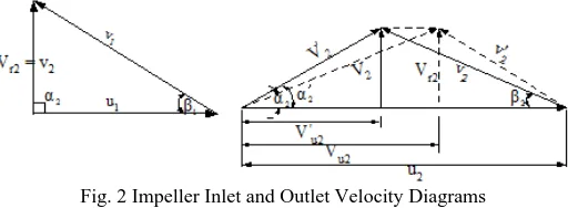
C. Impeller Inlet and Outlet Velocities
The simplified inlet and outlet velocities diagrams for the impeller are shown in Fig. 2. In this figure, the effect of circulatory flow on the outlet diagram is shown in solid lines and the virtual diagram is dotted. For a fluid flowing through the rotating impeller, u is the tangential velocity, V is the absolute velocity and
v is the relative velocity of a fluid particle to impeller rotation. The angle between V and u is α, and the angle between v and u is β and it is the angle made by tangent to the impeller vane and a line in the direction of motion of the vane. The tangential component and radial component of absolute velocity V are Vu and Vr
[image:2.612.317.573.266.360.2]respectively.
Fig. 2 Impeller Inlet and Outlet Velocity Diagrams
D. Determination of Impeller Inlet Dimensions and Vane Angle
A double-suction pump has a low percentage of leakage since the volume handled is relatively large compared to the leakage area. In this instance it will probably not exceed 2% [1]. The impeller is double-suction, so the total flow is divided by 2 and the approximate of impeller eye diameter will be.
D V
Q .
π
D H2
0 0
2 144 02 1 4
+ × ×
= (5)
The inlet velocity through the eye of the impeller V0 is usually
slightly higher than the velocity in the suction flange, say 10 to 15 ft/sec average. So, the assumed value of V0 is 11 ft/sec.
To insure smooth flow without excessive turbulence, the inlet vane edge diameter D1 is usually made about the same as the eye
diameter D0. Thus, tangential velocity at impeller inlet, u1 can be
expressed as
n π D u
60 12
1
1 = ×
(6)
The impeller inlet passage width for per side is
1 1 1 1
144
ε V πD
Q b
r
= (7)
Since slowing up a fluid is always more inefficient than speeding it up, the radial inlet velocity at the vane inlet, Vr1 is usually made
5% to 10% greater than V0. So, assumed value of Vr1 is 12 ft/sec.
Moreover, the inlet area will be increased by the vane thickness. Hence, a contraction factor ε1 which is generally between 0.8 and
The water is usually assumed to enter the vanes radially, so that the absolute approach angle α1 is 90º. And then, the vane inlet angle β1 is found from
1 1 1 tan u V β = r
(8)
The inlet relative velocity can also be expressed by
1 1 1 cosβ u =
v (9)
E. Determination of Impeller Inlet Dimensions and Vane Angle
The outlet diameter of impeller can be more easily obtained by means of the overall head coefficient Φ. The value of Φ varies between 0.9 and 1.2 with an average value very close to unity and this value is approximately taken as 1.05 in this study. Thus, the required outside impeller diameter is
n H Φ
D2 = 1480 (10)
And then, the peripheral velocity at impeller outlet is
n π D u 60 12 2
2 = × (11)
The vane outlet angle β2 is usually made larger than the inlet angle β1 to obtain a smooth, continuous passage. The amount of outlet angle β2 usually has between 15º and 40º. So, the vane outlet angle is assumed that β2 = 20º in this study.
The radial outlet velocity Vr2 is made the same as, or slightly
less (up to 15%) than the radial inlet velocity Vr1 to avoid any sudden changes of velocity. So, the radial outlet velocity Vr2 is
assumed that is 11 ft/sec.
To care for the vane thickness, a contraction factor ε2 which
is generally between 0.90 and 0.95 must be assumed in determining the gross outlet area and width b2 . If this is tentatively taken to be 0.925, the approximate outlet width is
2 2 2 2 144 ε V πD Q b r
= (12)
The virtual tangential component Vu2 of V2 is
2 2 2 2 β tan - r u V =u
V (13)
For radial-type impellers, the slip factor, η∞varies between 0.65 and 0.75and it is assumed that is 0.7 average. Thus, the actual tangential component V'
u2 of V '2 is ∞
′2 u2η u =V
V (14) Thus, the actual outlet is found by
2 2 2 tan u r V V = α ′
′ (15) To design correctly the volute or diffuser, the magnitude and direction of the absolute outlet velocity V2 of the liquid leaving the
impeller must be known. The absolute outlet velocity from outlet velocity diagram is
2 2 2
2 2= Vr Vu
V′ + ′ (16) And then, the water velocity at the impeller outlet is
2 2 2 inβ s V =
v r (17)
F. Impeller Blade Shape and Number of Blades
[image:3.612.325.581.86.323.2]A method of drawing the impeller blade by three circular arcs is used for this present design. Each radius is given by
Fig. 3 Curvature of Impeller Blade [3]
(
)
(
A B B)
B A A β -R β R -R R = ρ cos cos 2 2 2 2 (18)
(
)
(
B B C C)
C B B β R -β R R -R = ρ cos cos 2 2 2 (19)
(
)
(
1)
2 2
cos cos
2R β - R β
- R R = ρ D C C D C
C (20)
Where, RA, RB, RC and RD are base circle radii, RA=D2/2 and RD
= D1h/2.
3
-- A D
A B
R R =R
R (21)
3
-- A D
B C
R R =R
R (22)
The angles between β1 and β2 are divided into three angles. The vane thickness is scaled from the vane curvature drawing. In this design, the vane thickness at inlet width is 0.125 in (3 mm) and the thickness at outlet width is 0.275 in (7 mm). Moreover, the shroud thickness is taken as 0.19 in (5 mm).
The number of blades, Z is decided by using the Plfeiderer formula. It is
≈ 2 sin 56 1 2
1 2
1
2 β +β
D
D +D D .
Z (23)
IV. DESIGN OF PUMP'S VOLUTE CASING
A volute to fit the impeller designed is used and the purpose of the volute is to convert the velocity head of water leaving the impeller as efficiently as possible. Design of volute casing is calculated depending on the D2 and the basis of constant average
Fig. 4 Section through Volute Casing [1]
For pumps of medium specific speeds, b3 = 1.75 b2. For small pumps of lower specific speed (b2 is small), including multistage pumps, b3 = 2.0 b2. For high specific speed pumps (ns > 3000 double-suction) b3 can be reduced to b3 = 1.6 b2. Where b2 is impeller width at discharge and b3 is base width at D2 [4]. Thus, the base width in this study is taken as
2 3 1.75 b
b = ×
(24)
The width of the volute at any point is calculated from
× + =2 tan 2 b
b 3
θ
x (25)
Where, x is the distance between any radius R and impeller outside radius R2. The volute is designed by determining the angle Φº
measured from and assumed radial line by tabular integration of Equation (26).
∫
2∑
2
2 2 2
2 360
360 RΦ Φ
R
R
R u u
R ΔR b Q
V R R
bdR Q
V R =
Φo ′ = ′
(26)
The volute is considered to begin at the assumed base line, but it actually begins at the tongue radius Rt which 5% to 10% greater than the impeller radius R2 to avoid turbulence and noisiness and to give the velocities of the water leaving the impeller a chance to equalize before coming into contact with the tongue [7].The tongue angle of volute casing is determined by
2 2 10
tan log 132
α R R =
Φ t
t
′
o
(27)
To avoid shock losses the tongue should be made the same as the absolute outlet angle α2´ of the water leaving the impeller.
V. RESULTS OF DESIGNED TURBINE
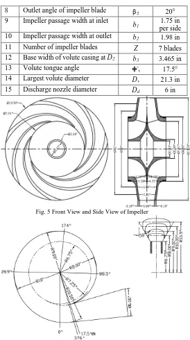
The calculated results for both impeller and casing design of double-suction type centrifugal pump are clearly expressed in Table I. Moreover, detail drawings of impeller and volute casing designs are also shown in following figures.
Table I. Required Parameters for Runner Design
No Descriptions Symbols Results
1 Input Power Pshaft 175 hp
2 Shaft diameter Ds 2.125 in
3 Hub diameter DH 2.5 in
4 Impeller eye diameter Do 7.3125 in
5 Impeller inlet diameter D1 7.3125 in
6 Impeller outlet diameter D2 13.5 in
7 Inlet angle of impeller blade β1 13°
8 Outlet angle of impeller blade β2 20°
9 Impeller passage width at inlet
b1 1.75 in
per side 10 Impeller passage width at outlet b2 1.98 in
11 Number of impeller blades Z 7 blades
12 Base width of volute casing at D2 b3 3.465 in
13 Volute tongue angle Φºt 17.5°
14 Largest volute diameter Dv 21.3 in
15 Discharge nozzle diameter Dd 6 in
Fig. 5 Front View and Side View of Impeller
Fig. 6 Drawing of Volute Casing: Elevation of Volute Casing and Section through of Volute Casing
VI. PERFORMANCE ANALYSIS OF DESIGNED PUMP
Performance needs to be known, not only at the rated, best efficiency point, but also off design. Pump specifications often impose special requirements, such as head at shut-off, maximum power demand, rate of head rise to assure stability, and so on. A good pump design process requires trail-and-error iteration, a check on anticipated performance with a trail geometry, and progressive approximation to the optimal design configuration.
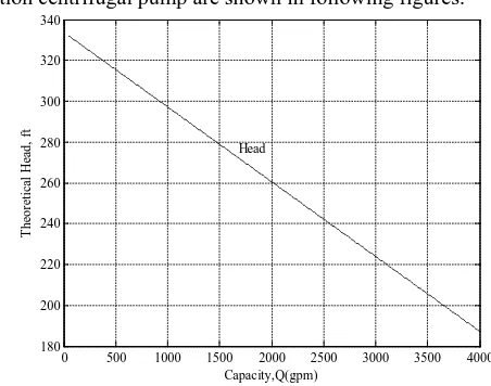
A. Theoretical Head and Net Theoretical Head
Firstly, theoretical head is calculated by
) ( 1
2 2 u
th u V
g =
[image:4.612.109.231.55.184.2]Where,
Whirl velocity, Vu2 = u2 – Vr2 cot β2
Flow velocity, 2 2 2 2 ε b πD Q =
Vr s
The circulatory flow effect reduces the theoretical head developed in a practically constant ratio. Slip value for circulatory effect is 70 0 2 1 2 sin 1 . Z ) β ( -
σ = (29)
By considering this effect, the whirl velocity and the net theoretical head are
2 2 2
2 = u σ-V cot β
Vu r (30)
) ( 1
2 2 u
thn u V
g =
H (31)
B.Shock Losses
Shock losses are considered as following expressing.
2 ) - Q = k (Q
hs s N (32) In the shut-off condition, Qs = 0 and QN is design flow rate at
maximum efficiency. Where, shut-off head is estimated by
g u = Hshutoff
2 u - 12 2 2
- (33)
From the shut-off condition, the value of k can be calculated.
C. Friction Losses
The wall friction or skin friction losses, Hf1 in the impeller
follow the standard pipe friction model. Since the flow passage cross sections are irregular, a hydraulic radius and average flow velocities are used. The friction coefficient can be adjusted but has a default value of 0.05 in this study. The impeller friction losses are calculated by the following Equation (34).
(
) (
)
(
β)
H × g × +v v -D D CF = H r f 4 sin2 2 1
2 1 2 1 2
1 (34)
Where, Hr1 refers to hydraulic radius and it is expressed by
) Z β π D + Z (b β D π b = Hr 2 2 2 2 2 2 1 sin sin (35)
The volute friction losses can be found by
π A g V D π = H th f 12 2
CF 3 32 2
×
(36)
Where V3 is the volute throat velocity and Ath is the volute throat
area. Their relationship is as follow [5].
th s
A Q =
V3 (37)
D. Diffusion Losses
A diffusion loss Hdf needs to be taken into account, since
separation invariably appears in the impeller at some point. When the ration of the relative velocity at the inlet v1 and outlet v2
exceeds a value of 1.4, it is assumed that a portion of the velocity head difference is lost. The diffusion loss is
g v . = Hdf 2 25
0 12
(38)
E. Actual Head
Finally, the actual pump head is calculated by subtracting from the net theoretical head all the flow losses. Thus, the actual pump head is forecasted by the following relationship equation.
H = Hthn– (hs + Hf1 + Hf2 + Hdf) (39)
F. Efficiency and Power
The overall efficiency can be predicted by the following relationship equation.
V HY
M×η ×η
η=η (40) The mechanical efficiency is
shaft vir s
M
P + q) H ρ g (Q
= t Power Input Shaf er Output pow =
η (41)
The hydraulic efficiency is
thn HY H H = r by impelle ted fluid head impar sured head actual mea =
η (42)
The volumetric efficiency is
+q Q Q age flow ernal leak flow+ delivered flow rate delivered = η s s v =
int (43)
By substituting these efficiencies into Equation (40), overall efficiency becomes
P ρgHQ η =
shaft s
In this study, input shaft power is 175 hp.
VII. PERFORMANCE CHARACTERISTICS OF DESIGNED
CENTRIFUGAL PUMP
[image:5.612.327.553.499.677.2]The performance characteristics of designed double-suction centrifugal pump are shown in following figures.
Fig. 7 Theoretical Head Curve
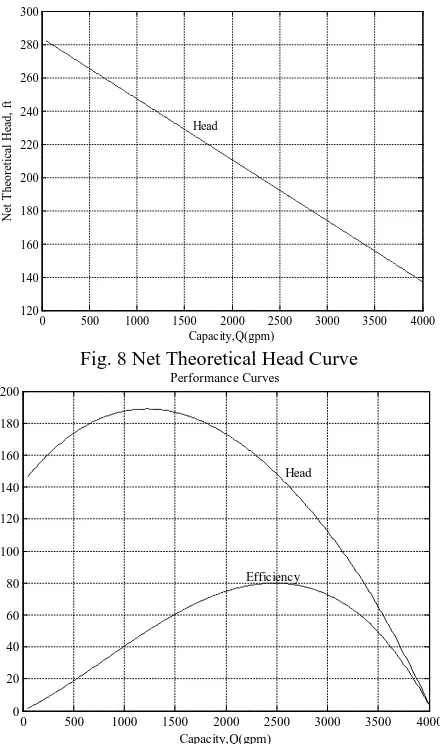
Fig. 8 Net Theoretical Head Curve
Fig.9 Performance Curves of Designed Centrifugal Pump
VIII. CONCLUSION
The designed pump is aimed to use in agriculture application for river pumping project which has about eight working hours per day and requires high head and capacity. So, double-suction centrifugal type is selected. The casing is horizontal split casing type. The designed pump can develop a head of 150 ft (46 m) and deliver 2500 gpm (9.48 m3/min) of water at 1760 rpm. The designed impeller has 7.32 in (13 cm) inlet diameter, 13.5 in (24 cm.) outlet diameter, 13º inlet vane angle and 20º outlet vane angle. The number of vanes is 7. And then, the inlet width and outlet width are 1.75 in (3 cm) and 1.98 in (5 cm) respectively. The clearance between impeller and tongue of volute is 1/2 in (1.3 cm). This value is a reasonably safe value for the tongue. The diameter of discharge flange is 6 in (15 cm). The thickness of volute casing to withstand the discharge pressure, 1/4 in is selected depending upon the suction pipe diameter, 10 in. When the performance of the designed pump is predicted, the maximum efficiency has nearly 80%. At the maximum efficiency condition, we observed that it reaches at the head of about 150 ft and capacity of about 2500 gpm
.
The materials to be used should be selected depending upon the type of water. The impeller is made of bronze to protect corrosion. To reduce the leakage from discharge to suction between the casing and impeller, the clearance must be made very small. It is used only to pump waterat 70º F and if very hot water is used this pump will be damaged. The designed double-suction centrifugal pump can fulfil the requirements of agriculture application and industrial application, and then can improve pump efficiency.
[image:6.612.316.589.117.330.2]APPENDIX
Fig. A Efficiencies as Related to Specific Speed and Flow Rate (source: The Pump Handbook published by McGraw Hill)
ACKNOWLEDGMENT
The author would like to express his special thanks to Dr. Aung Ko, Professor, Faculty of Precision Engineering, Technological University (Cyber City) and Daw Cho Cho Khaing, Associated Professor, Department of Mechanical Engineering, Technological University (Mandalay) for their kind supervision, encouragement, suggestion and valuable guidance of this paper.
REFERENCES
[1] Austin, H. Church, “Centrifugal Pump and Blower”, 1972, John Wiley and Sons, Inc, New York.
[2] Jacques Chaurett p. eng, "Fluide Design", Fluide Design Inc, 2005
[3] Kyushu Institute Technology, Training Course, “Fluid Mechanics of Turbomachinery”, Japan, 1996.
[4] Stepanoff. A. J, “Centrifugal and Axial Flow Pumps”, 1957
[5] Touzson, J, “Centrifugal Pump Design”, John Wiley and Sons, Inc, 2000. [6] EBARA Corporation, “Application of Pumps in Agriculture” Tokyo, Japan,
November, 1999.
[7] Khin Maung Aye, U, “Fluid Machinery for Mechanical Engineers”, December, 2000.
AUTHORS
First Author – Nyi Nyi, Ph.D (Mechanical), Faculty of Mechanical Precision Engineering, University of Technology (Yadanarpon Cyber City) and [email protected]
Second Author – Aung Ko, Ph.D (Mechanical), Faculty of Mechanical Precision Engineering, University of Technology (Yadanarpon Cyber City) and [email protected]
Third Author – Cho Cho Khaing, Department of Mechanical Engineering, Technological University (Mandalay), and [email protected]
0 500 1000 1500 2000 2500 3000 3500 4000 120
140 160 180 200 220 240 260 280 300
Capacity,Q(gpm)
N
et
T
h
eo
re
ti
cal
H
ead
, f
t
Head
0 500 1000 1500 2000 2500 3000 3500 4000
0 20 40 60 80 100 120 140 160 180 200
Capacity,Q(gpm) Head
![Fig. 1 Main Components of Double-suction Centrifugal Pump [1]](https://thumb-us.123doks.com/thumbv2/123dok_us/9050716.976520/1.612.339.546.527.722/fig-main-components-double-suction-centrifugal-pump.webp)
![Fig. 3 Curvature of Impeller Blade [3] ()](https://thumb-us.123doks.com/thumbv2/123dok_us/9050716.976520/3.612.325.581.86.323/fig-curvature-of-impeller-blade.webp)