Scholarship@Western
Scholarship@Western
Electronic Thesis and Dissertation Repository
12-10-2014 12:00 AM
Posture-Dependent Projection-Based Force Reflection Algorithms
Posture-Dependent Projection-Based Force Reflection Algorithms
for Bilateral Teleoperators
for Bilateral Teleoperators
Ali Moatadelro
The University of Western Ontario Supervisor
Dr. I. Polushin
The University of Western Ontario Joint Supervisor Dr. R. V. Patel
The University of Western Ontario
Graduate Program in Electrical and Computer Engineering
A thesis submitted in partial fulfillment of the requirements for the degree in Master of Engineering Science
© Ali Moatadelro 2014
Follow this and additional works at: https://ir.lib.uwo.ca/etd
Part of the Electrical and Computer Engineering Commons
Recommended Citation Recommended Citation
Moatadelro, Ali, "Posture-Dependent Projection-Based Force Reflection Algorithms for Bilateral Teleoperators" (2014). Electronic Thesis and Dissertation Repository. 2648.
https://ir.lib.uwo.ca/etd/2648
This Dissertation/Thesis is brought to you for free and open access by Scholarship@Western. It has been accepted for inclusion in Electronic Thesis and Dissertation Repository by an authorized administrator of
Force Reflection Algorithms for Bilateral
Teleoperators
(Spine title: )
(Thesis format: Monograph)
by
Ali Moatadelro
Graduate Program in
Electrical and Computer Engineering
A thesis submitted in partial fulfillment of the requirements for the degree of
Master of Engineering Science
School of Graduate and Postdoctoral Studies The University of Western Ontario
London, Ontario, Canada
c
Moatadelro, Ali, 2014
It was previously established that the projection-based force reflection (PBFR)
algo-rithms improve the overall stability of a force reflecting teleoperation system. The idea
behind the PBFR algorithms is to identify the component of the reflected force which
is compensated by interaction with the operator’s hand, and subsequently attenuate
the residual component of the reflected force. If there is no a priori information re-garding the behaviour of the human operator, the PBFR gain is selected equal to a
sufficiently small constant in order to guarantee stability for a wide range of human
operator responses. Small PBRF gains, however, may deteriorate the transparency
of a teleoperator system. In this thesis, a new method for selecting the PBFR gain
is introduced which depends on the human operator posture. Using an online human
posture estimation, the introduced posture-dependent PBFR algorithm has been
ap-plied to a teleoperation system with force feedback. It is experimentally demonstrated
that the developed method for selection of the PBFR gain based on human postures
improves the transparency of the teleoperator system while the stability is preserved.
Finally, preliminary results that deal with an extension of the developed methods
towards a more realistic model of the human arm with 4 degrees of freedom and three
dimensional movements are presented.
Keywords: Teleoperation system, stability, transparency, passivity, small gain
the-orem, projection-based force algorithm, velocity and force transmission rates.
It is my great pleasure to express my sincere appreciation to my supervisors, Dr. Rajni
V. Patel and Dr. Ilia Polushin, for their constant support, guidance and
encourage-ment during my masters program. I am very grateful for their patience, knowledge
and insightful advice. Besides all the help, I am also thankful for their invaluable
comments and constructive suggestions to improve this thesis. I particularly thank
Dr. Polushin for patiently answering my numerous questions and helping me to find
my path.
I would also like to thank my defense committee members, Dr. Lyndon Brown,
Dr. Ana Luisa Trejos and Dr. Louis Ferreira for providing valuable comments on my
thesis.
I would like to especially thank my great friend and collaborator Dr. Amir
Takhmar. I really appreciate all his help throughout my study and his consultation
to this work. Amir is also a collaborator of part of this thesis. It is also my pleasure to
thank my dear friend Nima Najmaei for amazing time we spent together, discussions
we had and the help that I received from him during my study.
Last, but not least, I would like to thank my lovely wife, Yalda, for her endless
love, encouragement and support. I am grateful to have her in my life.
I would like to thank all sources of funding for their support.
Financial support for this study was provided by the Natural Sciences and
Engineering Research Council (NSERC) through the Discovery Grant # RGPIN1345
awarded to Dr. Patel and # RGPIN 1510 awarded to Dr. Polushin. Financial support
for A. Moartadelro was also provided by an Ontario Graduate Scholarship.
Memory of M.
Abstract . . . ii
Acknowledgments . . . iii
Sources of Funding . . . iv
Dedication . . . v
List of Notations . . . viii
List of Acronyms . . . x
List of figures . . . xi
1 Introduction . . . 1
1.1 Contributions . . . 3
1.2 Thesis outline . . . 3
2 A Survey of Teleoperation . . . 5
2.1 Passivity based approach . . . 7
2.1.1 General properties of the robot dynamics . . . 10
2.1.2 Stability vs. Transparency . . . 15
2.1.3 The effect of time delay on stability and transparency . . . 16
2.1.4 Scattering transformation . . . 17
2.1.5 Wave variables method . . . 19
2.1.6 Geometry behind the scattering method . . . 20
2.1.7 Time varying delay . . . 23
2.2 Small gain approach . . . 24
2.3 Projection-based force reflection algorithms . . . 26
2.4 ISS & IOS for functional differential equation . . . 28
2.5 Conclusions . . . 31
tems . . . 33
3.1 Theoretical background on task manipulability . . . 35
3.1.1 Velocity and force ellipsoids . . . 35
3.1.2 Remarks . . . 39
3.2 Simulation results of the human arm response to a disturbance force for different postures . . . 44
3.3 Experimental results: human postures and stability . . . 57
3.4 Conclusions . . . 62
4 A Posture-Dependent Algorithm for Selecting the PBFR Gain . . 63
4.1 Human posture and the stability of the teleoperator system: experi-mental results . . . 64
4.1.1 Experimental results . . . 64
4.2 A posture dependent selection of the PBFR gain . . . 66
4.3 The posture dependent PBFR gain and stability: experimental results 69 4.4 Conclusion . . . 71
5 A Posture Dependent PBFR Gain for Teleoperation System with Online Posture Estimation . . . 72
5.1 Online posture estimation . . . 72
5.2 Experimental setup . . . 73
5.2.1 Discussion on the stability . . . 94
5.3 Conclusion . . . 95
6 Towards a 4-DOF model of human arm . . . 96
6.1 A 4-DOF human arm model; Denavit-Hartenberg representation . . . 97
6.1.1 The forward kinematics of the 4-DOF human arm model . . . 97
6.1.2 Inverse Kinematics of the 4-DOF human arm model . . . 101
6.1.3 Simulation of the human arm model and associated velocity ellipsoids . . . 104
6.2 Dynamics of the 4-DOF human arm model . . . 104
6.2.1 Simulation of effect of human postures on the stability of the system; a regulation problem . . . 108
6.3 An adaptive PBFR gain . . . 117
6.4 Concluding remarks . . . 118
7 Conclusion and future work . . . 119
7.1 Future work . . . 120
Appendix . . . 122
MATLAB codes . . . 122
Vita . . . 138
Notation
q,q,˙ q¨ Generalized coordinate, velocity and acceleration
vh Human velocity
vl, vr Local-remote manipulator velocity
vrd Delayed remote manipulator velocity
fe, fenv Environment force
fl Local manipulator force
fld Delayed local force
ϕenv Interaction component of reflected force
M(ql), M(qr) Local-remote inertia(metric) tensor
C(q,q˙) Centrifugal/Coriolis matrix
G(q) Gravity vector filed
Γijk Christoffel symbols
L Lagrangian
K Kinetic energy
τ Torque/input control
H Hybrid matrix
h,i Inner product
h,it Finite time inner product
||.||p p-norm
λmin, λmax Maximum and minimum eigenvalues
Z(s) Impedance transformation
S(s) Scattering transformation
S∗ Adjoint of scattering matrix
T, Ti(t), τ(t) Constant and variable time delay
γ(.) gain of a nonlinear system
Sat[a,b](x) Saturation function
sup Supremum
lim supt→∞ Limit supremum
θ Joint angles of a manipulator
J Jacobian matrix
JT Jacobian transpose
βu Velocity transmission rate in direction u
mu Effective mass in direction u
Kp, Kd PID controller coefficients
φenv Projected force component in PBFR
α Gain of PBFR
PBFR Projection based force reflection
ISS Input-to-state stability
IOS Input-to-output stability
WIOPS Weak input-to-output practical stability
RTT Round-Trip Time
2.1 Teleoperator system; vh, vl, vrd, vr represent human velocity, local locity, delayed velocity received at remote manipulator, and remote ve-locity. fe, fr, fld, fl are environment force, remote force, delayed force
received at the local manipulator (master), and the local force. . . 7
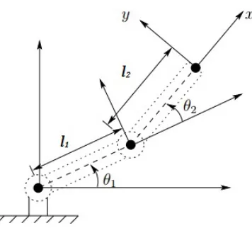
2.2 A 2-DOF manipulator. . . 8
2.3 Two dimensional torus S1×S1 . . . 9
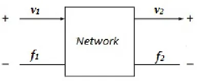
2.4 Two-port network . . . 15
2.5 Wave variable method . . . 19
2.6 Time dependent gain for interconnection medium with time varying delay . . . 23
3.1 Principle axes of a ellipsoid are given by the eigenvectors of the sym-metric matrix associated with the quadratic form of the ellipsoid. The ellipsoid diameters are given by the 1/√λi’s, whereλi’s are eigenvalue of the ellipsoid defining symmetric quadratic form. . . 36
3.2 The transmission force rate in direction of the unit vector u is the length of the segment line from the centre of ellipse (ellipsoid) to the boundary of the ellipse (ellipsoid) in the direction u. . . 38
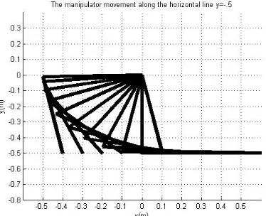
3.3 Experiment 1: The manipulator movement in a horizontal line; eleven positions of the end effector on the horizontal line y = −0.5 for x = −0.4 + 0.1i, i= 0,· · ·10. . . 47
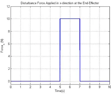
3.4 Experiment 1: The disturbance force inx-direction . . . 48
3.5 Experiment 1: Transmission rate βx (left) and displacement in x -direction in the horizontal movement (right) . . . 48
3.7 Experiment 1: The transmission rate βy (left) and displacement in y-direction in the horizontal movement (right) . . . 49
3.6 Experiment 1: The disturbance force iny-direction . . . 49
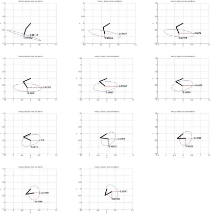
3.8 Experiment 1: Velocity ellipsoids during horizontal movement along the liney=−0.5 forx=−0.4 + 0.1i, i= 0,· · ·10, the red dashed lines show the horizontal and vertical transmission ratesβx, βy . . . 50
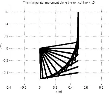
3.9 Experiment 2: The manipulator movement in a vertical line; eleven positions of the end effector on the vertical linex= 0.5 fory=−0.4 + 0.1i, i= 0,· · ·10. . . 51
3.11 Experiment 2: The transmission rate βy (left) and displacement in y direction in the vertical movement (right) . . . 52
3.10 Experiment 2: The transmission rate βx (left) and displacement in x direction in the vertical movement (right) . . . 52
the linex = 0.5 for y=−0.4 + 0.1i, i= 0,· · ·10, the red marble lines
show the horizontal and vertical transmission ratesβx, βy. . . 53
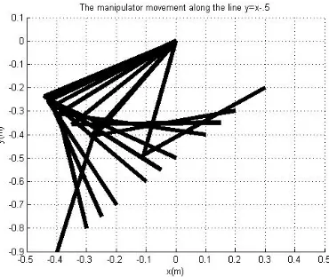
3.13 Experiment 3: The manipulator positions along a slanted line . . . . 54
3.14 Experiment 3: The transmission rate βx (left) and displacement in x direction in the slanted movement (right). . . 54
3.15 Experiment 3: The transmission rate βy (left) and displacement in y direction in the slanted movement (right). . . 55
3.16 Experiment 3: Velocity ellipsoid during slant movement along the line y = −0.5 +x for x = −0.4 + 0.1i, i = 0,· · ·10, the red dashed lines show the horizontal and vertical transmission ratesβx, βy. . . 56
3.17 Exprimental setup . . . 57
3.18 PhantomOmniTM haptic device . . . 58
3.19 The velocity ellipse and the human posture 1 . . . 59
3.20 The velocity ellipse and the human posture 2 . . . 60
3.21 The velocity ellipse and the human posture 3 . . . 60
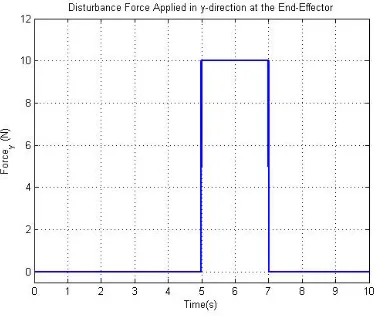
3.22 The disturbance force in the vertical direction . . . 60
3.23 The human force and induced motion according to the vertical distur-bance force for postures 1, 2 and 3 . . . 61
3.24 The disturbance force in the horizontal direction . . . 61
3.25 The human force and induced motion according to the horizontal dis-turbance force for postures 1, 2 and 3 . . . 62
4.1 The human force and reflected force for postures 1-3(top to bottom) with constant PBFR gain in response to a horizontal disturbance force 67 4.2 The human force vs. the reflected force in postures 1-3 with direct force reflection, constant PBFR gain and variable PBFR gain (left), the induced motion for direct force reflection, constant PBFR gain and variable PBFR gain in postures 1-3 (right) . . . 70
5.1 The process of online posture estimations by detecting the wrist, elbow and shoulder positions using a camera. The center of the area of the green markers will be detected and connected to make a 2-DOF model of human arm. . . 73
5.2 Structure of teleoperator system with projection-based force reflection and on-line posture estimation. . . 74
5.3 Experimental setup . . . 74
5.4 Experimental setup for on line estimation of the human postures to adjust the variable PBFR gain . . . 75
5.5 On line estimation of the human postures to adjust the variable PBFR gain; in the web-cam picture in the monitor, the online attachment velocity based ellipsoid based on the human posture is shown. . . 76
5.6 Posture 1 . . . 77
5.7 Posture 2 (left) and Posture 3 (right) . . . 77
for direct force reflection case for Postures 1-3 (top-bottom). The vir-tual wall perpendicular to x-direction. . . 78 5.9 Velocity transmission rate in postures 1, 2 and 3 (top to bottom) for
direct force reflection case. The virtual wall orthogonal to x-direction. 79 5.10 Contact versus reflected force (left), local manipulator trajectory (right)
for direct force reflection case for Postures 1-3 (top-bottom). The vir-tual wall perpendicular to y-direction. . . 81 5.11 Velocity transmission rate in postures 1, 2 and 3 (top to bottom) in
direct force reflection case; y-direction. . . 82 5.12 Contact vs. reflected force (left), local trajectory (right) with constant
PBFR gain α = 1 (top), constant PBFR gain α = 0.1 (middle) and time varying α (bottom). Human is in Posture 1 and virtual wall orthogonal to x−direction. . . 84 5.13 PBFR gain (left) and velocity transmission rate (right) with constant
PBFR gain α = 1 (top), constant PBFR gain α = 0.1 (middle) and time varying α (bottom). Human is in Posture 1 and virtual wall orthogonal to x−direction. . . 85 5.14 Contact vs. reflected force (left), local trajectory (right) with constant
PBFR gain α = 1 (top), constant PBFR gain α = 0.1 (middle) and time varying α (bottom). Human is in Posture 3 and virtual wall orthogonal to x−direction. . . 86 5.15 PBFR gain (left) and velocity transmission rate (right) with constant
PBFR gain α = 1 (top), constant PBFR gain α = 0.1 (middle) and time varying α (bottom). Human is in Posture 3 and virtual wall orthogonal to x−direction. . . 87 5.16 Contact vs. reflected force (left), local trajectory (right) with constant
PBFR gain α = 1 (top), constant PBFR gain α = 0.1 (middle) and time varying α (bottom). Human is in Posture 1 and virtual wall orthogonal to y−direction. . . 89 5.17 PBFR gain (left) and velocity transmission rate (right) with constant
PBFR gain α = 1 (top), constant PBFR gain α = 0.1 (middle) and time varying α (bottom). Human is in Posture 1, and virtual wall orthogonal is to y−direction. . . 90 5.18 Contact vs. reflected force (left), local trajectory(right) with constant
PBFR gain α = 1 (top), constant PBFR gain α = 0.1(middle) and time varying α (bottom). Human is in Posture 3, and virtual wall orthogonal is to y−direction. . . 91 5.19 PBFR gain (left) and velocity transmission rate (right) with constant
PBFR gain α = 1 (top), constant PBFR gain α = 0.1 (middle) and time varying α (bottom). Human is in Posture 3 and virtual wall orthogonal to y−direction. . . 92 5.20 Posture dependent PBFR gain α(βx) and the velocity transmission
rate βx, Posture 3. . . 93
rate βy, Posture 1. . . 94
6.1 Coordinate system of the arm . . . 99 6.2 The velocity ellipsoid of the 4-DOF model of human arm; the principal
axes are denoted by dashed red lines. . . 101 6.3 The 4-DOF model of human arm: Velocity ellipsoid during a circular
motion on the path given by (l1/√2 +l2sint, l2cost, l1/√2) for t = −1 : 0.2 : 0.6. The principle axes of the ellipsoid is shown by red dashed lines. . . 105 6.4 The human arm movement on the path given by the (6.14). . . 108 6.5 The velocity transmission rates βy (up-left), βz (up-right) and βw
(down-left), wherewis the forearm direction and human arm postures are given by (6.14). . . 110 6.6 Left: trajectoriesθ vs desired trajectoriesθdfor forceFz = 3 N. Right:
torques τ applied to the joints for Posture 1 (top) to Posture 3 (bot-tom). Postures are give by (6.14). . . 112 6.7 Left: trajectoriesθ vs desired trajectoriesθdfor forceFz = 3 N. Right:
torques τ applied to the joints for Posture 4 (top) to Posture 6 (bot-tom). Postures are give by (6.14). . . 113 6.8 Left: trajectories θ vs desired trajectories θd for force Fw = 3 N.
Right: torques τ applied to the joints for Posture 1 (top) to Posture 3 (bottom). Postures are give by (6.14). . . 114 6.9 Left: trajectories θ vs desired trajectories θd for force Fw = 3 N.
Right: torques τ applied to the joints for Posture 4 (top) to Posture 6 (bottom). Postures are give by (6.14). . . 115 6.10 Control input τ4 applied to the fourth joint for Posture 1 (top-left) to
Posture 6 (bottom-right). Blue: force applied in z−direction, black: force applied in y−direction and red: force applied in direction w. Postures are give by (6.14). . . 116
Introduction
Telerobotics is a part of robotics which deals with remote control of robots. An
important part of telerobotics isteleoperation, which means operating at a distance. A teleoperator system consists of two separate manipulators, called alocal manipulator
and aremote manipulator which communicate information, usually position, velocity and/or force, through a communication channel. The remote manipulator follows
the local manipulator to execute a task on a remote environment. When the remote
manipulator is in contact with its environment, it may be desirable to send the contact
force information to the local manipulator, since this provides the human operator
with better understanding of the contacted environment and hence can improve the
performance of the system during task execution.
Although force feedback provides the human operator with a better
under-standing of contact tasks, at the same time it may create problems such as instability
of the system due to unwanted motion caused by the reflected force from the
con-tacted environment. In certain tasks where a high level of precision is needed, such
as telesurgery, handling hazardous materials, etc., this instability may result in
dan-gerous situation or even cause irreversible damage. Projection-Based Force Reflection
(PBFR) algorithms were introduced to address this issue [58, 59, 60]. The idea
be-hind PBFR algorithms is to decompose the force reflection signal into interaction and
motion-generating components, and subsequently attenuate the latter while applying
the former in full. The interaction component of the reflected force is defined as
ϕenv := Sat[0,1]
( ¯ fhTfenv |f¯h|2+
)
¯ fh,
wherefenv is the force feedback from the remote side, ¯fhis the estimate of the human
force applied to the haptic device, and > 0 is a small number introduced to avoid
the ambiguity arising when ¯fh= 0. The algorithm finds the interaction component as
the projection of force feedback on the direction of the human force with magnitude
bounded by the magnitude human force. The PBFR algorithm suggests to generate
the force reflection signal as a convex combination of the direct force feedback and
the projection-based component:
fr =αfenv+ (1−α)ϕenv,
where α ∈ [0,1]. It is shown [61] that the PBFR algorithm improves the stability
of the force reflecting teleoperator system with haptic interface without considerable
transparency deterioration. In addition, it has been shown [61] that the algorithm
guarantees the convergence of the reflected force to the contact force in teleoperator
systems when in contact with the environment. Because of the fact that there is no
a priori information of the human operator forces, the PBFR gain α is chosen small
enough to cope with a wide range of human operator responses. Although a small
PBFR gain α >0 implies stability of the system, it increases the transient time and
hence decreases the performance of the system. Therefore, selecting the gain so that
it keeps a reasonable level of stability and transparency at the same time will be a
question of interest and is the core of this thesis. To be more precise, we look at an
issue that has not been discussed in earlier research works on PBFR algorithm which
is the effect of the human posturing on the stability of a teleoperator system when
the PBFR algorithm is applied. The main idea is to adjust the PBFR gain α based
on the human postures (or, more precisely, based on the force transmission ratio of the human hand in the direction of the reflected force, which is roughly speaking a
measure of the human capability for compensating an external force). Our method
a task; instead, one can select the gain according to human postures, with small
values only selected for the cases where the human hand cannot compensate for the
reflected force. The method is applied to a single-local single-remote force feedback
teleoperator system using a webcam to detect the human posture online and update
the gain at each instant in time during execution of a task. Our suggested method is
supported by simulations and experimental results which show how the performance
of the system is improved in comparison with the usual PBFR algorithm.
1.1
Contributions
The main objectives/contributions of this thesis can be summarized as follows:
• Survey of the research studies on a teleoperator system from a control theoretic
point of view which covers the stability and transparency issues associated with
a teleoperator system with force feedback. Two approaches, i.e.,
passivity-based and small gain methods are discussed and the (selected) related issues
are addressed as well as suggested solutions.
• Development of a new method for on-line selection of PBFR gain based on the
human operator postures (instead of the non-posture dependent gain applied in
the earlier related works).
• Improvement of the transparency of a force reflecting teleoperator system, using
the new posture dependent projection-based gain and online posture estimation,
while the stability of the system is preserved, compared to the projection-based
force reflection algorithm with a non-posture dependent gain.
1.2
Thesis outline
Here is the outline of this thesis. Chapter 2 is a literature review of the stability and
approaches to study stability of the system, i.e., passivity based and small gain
meth-ods. In Chapter 3, we review elements of task manipulability and also investigate the
effect of human posturing on the performance of a haptic interface. In Chapter 4,
a new posture-dependent projection-based force reflection gain dependent on human
postures is introduced and experimental results are provided to demonstrate the
per-formance of the system with the new posture-dependent PBFR gain versus constant
PBFR gain. Chapter 5 is devoted to applying the mentioned posture-dependent gain
to teleoperation systems, using an online human posture estimation. Chapter 6
dis-cusses a generalization of our method to a more realistic model of the human arm
with 4 degrees of freedom and 3-dimensional movement, unlike the 2-DOF planar
model of the arm adopted in the earlier chapters. Finally, in Chapter 7, the thesis
A Survey of Teleoperation
Over the past few decades the progress in telerobotics has changed our vision as well
as our expectation of robots. The idea that a robot can be controlled in a remote
environment brings a number of capabilities with extensive amount of applications,
from undersea to space exploration, and from robotic telesurgery and high precision
assembly to handling heavy loads and hazardous materials.
An important part of telerobotics is teleoperation, that is operating at a dis-tance. A teleoperator system usually consists of two separate manipulators, called
local manipulator and remote manipulator which are connected through a communi-cation channel. The local and remote manipulators exchange information (usually,
force, position and/or velocity) through this communication channel. The remote
manipulator, which might have some degrees of autonomy, will follow the local
ma-nipulator to execute a task on a remote environment (Figure 2.1). A teleoperation
system with one local and one remote manipulator is called single-local single-remote teleoperation system and a teleoperation system with more than one local and more than one remote manipulators is calledmulti-local multi-remote teleoperation system. When the remote manipulator is in contact with an environment, in order to provide
a better understanding of the contact environment for the human operator at the
local side and hence achieve a higher level of performance, it is frequently desirable
to send the interaction force information to the local manipulator. Such a force
feed-back, however, may cause a number of difficulties such as instability which will be
explained later in this chapter. For example, the current commercial telesurgical
min-imally invasive surgery (MIS) systems do not provide force feedback due to the above
mentioned issues. However, there are experimental results demonstrating that the
haptic feedback improves the task performance. Two main requirements associated
with the force reflecting teleoperation systems are stability and transparency of the system. There are several definitions of stability such as Lyapunov stability, input-output stability, input-to-state (input-to-input-output) stability, etc.; some of them will be explained later in this chapter. A rigorous definition of transparency will be
pre-sented later in this chapter; informally, a system is called transparent if the received
signals at local (respectively, remote) side are the same as sent signals from remote
(respectively, local) side. Transparency also can be defined in terms of impedance
matching, in the sense that the transmitted to human impedance is equal to the
envi-ronmental impedance [42]. In this case, the difference between these two impedances
can be considered as a measure of transparency. Cooperation between local and/or
remote manipulators during a task execution is advantageous in many applications
such as robotic telesurgery, high precision assembly, heavy loadings and handling
hazardous materials. In these tasks, lack of stability and/or transparency may result
in unsuccessful task execution and even irreversible damage. It is known that [72],
in the presence of the delay in the communication channel, the teleoperation system
may become unstable. In some cases, communication delay is a known constant but
this does not hold in the case of teleoperation over the Internet which has recently
been widely accepted as a communication medium. The time delay function in the
case of communication over the Internet is typically time-varying and unknown. The
stabilization techniques used in the case of constant communication delays will not
guarantee stability of the system in the presence of time-varying delays. On the
other hand, the transparency of the system, which is usually a conflicting goal with
the stability, can be achieved by a different approach. In addition to the stability
and transparency issues of the teleoperator systems, the possibility of data dropouts
in the communication channel is another problem that might occur because of the
Figure 2.1: Teleoperator system; vh, vl, vrd, vr represent human velocity, local veloc-ity, delayed velocity received at remote manipulator, and remote velocity. fe, fr, fld, fl are environment force, remote force, delayed force received at the local manipulator (master), and the local force.
useful to forget the old packet and send new packets which contain the recent
in-formation [75], but significant amount of data dropouts will cause discontinuity of
the reference trajectories and forces transmitted between the local and the remote
manipulators.
In the next section, we discuss some recent results that address the issues of
the teleoperation systems in the presence of the communication delay, as well as
two main approaches to the design of teleoperator systems, i.e., passivity-based and
small-gain-based approaches, to tackle problems arising in this area.
2.1
Passivity based approach
A challenging problem in teleoperation systems design is to achieve stability and
transparency of the system at the same time which are frequently conflicting goals;
therefore, usually some trade-off between stability and transparency is required. To
find an accurate relationship between these two determining factors of performance
is a challenging problem.
An important step in the design of control algorithms in robotics is
system in our context is given by
X
i
mkj(q)¨qj +X i,j
Γijkq˙iq˙j +gk(q) =τk, k = 1,2,· · · , n, (2.1)
where q = (q1, q2,· · · , qn)T describes trajectory of the motion on a n−dimensional smooth manifold. Velocity and acceleration of the motion are given by the time
derivatives ˙q,q¨. We recall that an n−dimensional manifold is a (topological) space
that locally looks like the Euclidean space Rn. In the cases that are of interest for
our work, the manifold is usually a compact smooth sub-manifold of aN-dimensional
Euclidean space, for some positive integer N. For example, in the case of a two
degrees-of-freedom manipulator shown in Figure 2.2, the configuration space is the
compact 2-dimensional manifold S1 ×S1 (Figure 2.3), where S1 is the unit circle defined as S1 ={z ∈C| |z|= 1}.
Figure 2.2: A 2-DOF manipulator.
The elements mij are the components of the metric/inertia matrix (more
pre-cisely, the type 2-covariant metric tensor). The Christoffel symbols Γ’s are given by the partial derivatives of the metric tensor, mij, as
Γijk := 1
Here, as it is conventional in differential geometry and physics, subscripts will be used
for the covariant components of a tensor, andfi = ∂q∂f
i. The gravity term is given by gk and τk is the external force.
Figure 2.3: Two dimensional torus S1×S1
In control literature, the dynamics are typically described by the Euler-Lagrange
equations of the form
M(q)¨q+C(q,q˙) ˙q+G(q) = τ, (2.3)
whereτ = (τ1, τ2,· · ·, τn)T ∈Rn is the external force,M(q) = (mij(q)) is the inertia matrix, C(q,q˙) = (cij(q,q˙)) is called the Coriolis and centrifugal matrix given by
cij =X l
Γlijq˙l,
and G(q) = (g1(q),· · · , gn(q))T is the gravity vector field. These equations of mo-tion can be obtained for example by applying the Euler-Lagrange equamo-tions to the
Lagrangian L=K −P of the system, where K and P are the kinetic and potential
energy of the system, respectively. We assume that the kinetic energy is given by a
quadratic form defined by a symmetric positive definite matrixM = (mij(q)) as
K = 1 2
X
ij
mij(q) ˙qiq˙j,
Euler-Lagrange equations are given by
d dt
∂L ∂q˙i −
∂L
∂qi =τi, i= 1,2,· · · , n.
The terms ∂∂Lq˙ i and
∂L
∂qi are calledgeneralized momentumandgeneralized force, respec-tively. In telerobotics, the dynamics of the system is given by a pair of equations of
motion, one for the local manipulator and one for the remote manipulator as follows,
Mlq¨l +Clq˙l +Gl =τl
Mrq¨r+Crq˙r+Gr =τr.
(2.4)
In this chapter, we use subscripts l, r for local and remote manipulators and drop
the argument of the matrices, whenever there is no place for confusion. For example,
we use M(ql) for the local inertia matrix instead of Ml(ql) and also we use the brief
notation of Ml :=M(ql).
2.1.1
General properties of the robot dynamics
The matrices in the above equations of motion enjoy a few important properties that
we mention here.
Property 1. The matrix ˙M −2C is skew symmetric, that is, for any vector
v, one has (v,( ˙M −2C)v) = 0. Here, (u, v) =P
iuivi is the usual inner product for
vectors u, v ∈ Rn. In fact the skew-symmetric property of ˙M −2C follows from the
equation
˙
mij −2cij =X k
∂m
jk
∂qi − ∂mik
∂qj
˙ qk.
We note that, for any size n matrix Aand vector v ∈Rn, by expanding with respect
to an orthonormal basis, one has (v, Av) = P
i,jaijvivj, where vi’s and aij are
skew symmetric. The skew symmetric property of M˙ −2C is also equivalent to
˙
M =C+CT.
An immediate consequence of this property is the passivity of the system.
Con-sider a nonlinear system given by
˙
x(t) = f(x(t), u(t))
y(t) = h(x(t))
(2.5)
wherex(t) = (x1(t),· · · , xn(t)) is the state of the system which belongs to Euclidean space Rn at each instant time t, u(·) : [0,∞) → Rp is the input, control or
distur-bances depending on the context, and y(t) = (y1(t),· · · , yp(t)) is the output of the system for some positive integers n, p. The function f :Rn+p →Rn is locally Lips-chitz and h:Rn →Rm is continuous. We omit the argumentt usually. The solution
x(t, x0, u) is considered on a maximal interval [0, tmax(x0, u)) for the initial state x0
and the input u. For a system with no input,
˙
x(t) =f(x(t)), (2.6)
the solution is denoted byx(t, x0). The zero input system associated with ˙x=f(x, u) is the system ˙x=f(x,0).
Definition 2.1.1. The system given by (2.5), is called passive if
hy, ui ≥ −β for some β ≥0. (2.7)
Here, the inner product of the two signals v(t) = (v1(t),· · · , vp(t)) and w(t) = (w1(t),· · · , wp(t)) is given by
hv, wi=
∞ Z
0
This integral shows the energy absorbed by the system, and β at the right side of
the definition can be thought as the initial energy stored at the system. To avoid
the complexity arising from the Lebesgue integral, one can consider just piecewise
continuous signals. As it can be seen, passivity is an input-output property of the
system. In fact, it measures the exchanged power/energy between the interconnected
subsystems. The passivity of a dynamical system can also be defined equivalently as
follows [62]:
Definition 2.1.2. The dynamical system (2.5) is called passive if there exists a pos-itive semidefinite C1-function V :Rn→R, such that
˙
V ≤uTy.
The function V is called a storage function of the system. Establishing the passivity of a system allows one to consider sum of storage functions of the subsystems
as a Lyapunov function candidate for the system to prove the stability, assuming the
environment and the human operator are passive. We recall that the system (2.5) is
Lyapunov stable at x = 0 if for any > 0, there exists a δ > 0 such that |x(0)| < δ yields that x(t) < for all t > 0. It is well known that the existence of a so called
Lyapunov function, which is a positive definite function on a region containing origin
with a negative definite time derivative, implies the Lyapunov stability. We will refer
to [62] for more details on generalizations of this definition.
Note that here and in the following, we use the notation | · | for the standard
Euclidean norm, i.e., |v|=
q
v12+· · ·+v2n for a vector v ∈Rn.
We will use the notation hv, wit for the integration on the finite time interval
[0, t], that is,
hv, wit = t
Z
0
The norm induced by h,i is called the L2-norm and is denoted by ||v||2 = hv, vi1/2. The Lp− norm is defined by
||v||p=
∞ Z
0
|v|p
1
p .
A bounded signal is a signal whose norm, which is appropriately chosen de-pending on the context, is finite. When the Lebesgue integral is applied, the space of
signals with boundedLp−norm is called the Lpspace, which is a Banach (and hence a normed)space. In the special case thatp= 2, this will also be aHilbert space with a complete set of orthonormal basis. This is a crucial fact in proving Parsvall’s iden-tity, which gives us the ability to find the norm of a signal in the frequency domain instead of time domain.
As it is already mentioned, passivity of a system is equivalent to the existence of
a storage function [36], which is closely related to the Lyapunov function. An
impor-tant feature of passive systems is the fact that the negative feedback interconnection
of passive systems is also passive and stable [36].
Now, let us go back to the dynamic equations of a teleoperation system.
Property 2. The system (2.5) is passive, i.e., the following holds for some
β ≥0 and for all t1 >0,
t1
Z
0
˙
q(t)Tτ(t)dt ≥ −β.
The quantity ˙qTτ is the power flow of the system. To see the passivity of the system,
one can consider the total energy of the systemE =K+P. Then the time derivative
of the total energy is given by
˙
E = ˙qTMq¨+1 2q˙
TM˙ q˙+ ˙qT∂
where ∂qP is the gradient of the potential energy. Therefore, one has
t1
Z
0
˙
q(t)Tτ(t)dt =E(t1)−E(0)≥ −E(0),
which yields the passivity of the system for β=E(0). Note that, the passivity holds
for both local and remote manipulators.
Property 3. Another important fact about the symmetric positive definite
matrix M is the following inequality which holds at each pointq
λmin(M(q))|v|2 ≤vTM(q)v ≤λmax(M(q))|v|2.
Here λmin(M(q)), λmax(M(q)) > 0 are minimum and maximum eigenvalues of the
positive definite matrixM(q). This is a point-wise property, but if the configuration
space is a compact space, which is the case when joints are revolute and/or prismatic
with finite range of motion, we have
λ1|v|2 ≤vTM(q)v ≤λ2|v|2, for some λ1, λ2 >0.
Property 4. The next important property is about the matrix C and its
bounded-ness. In fact,
|C(q,q˙) ˙q|< K|q˙|2, for some K >0.
Property 5. The last property that we mention here is, the equations of motion can
be linearly parameterized as Mq¨+Cq˙+G=Y(q,q,˙ q¨)Θ. For details on proof of the
mentioned properties, reader is referred to [41, 62].
It was around 1980s that it was realized that a local-remote teleoperator system
can be modeled as a two port network (Figure 2.4), which was already introduced
and studied in literatures [8, 26, 27, 28]. The two-port network properties can be
Figure 2.4: Two-port network
The impedance matrix for the 2-port network is relating velocities to forces as
f1
f2
=Z(s) v1 v2 ,
Each component ofZij(s) has an expression in terms of local, remote impedance and
controllers. Here, fi, vi are the force and velocity signals in frequency domain.
The hybrid matrix of the two-port network system, H, is defined as
f1
−v2 =
h11 h12
h21 h22 v1 f2
, (2.8)
where hij are the components of the matrix H; the above equation is written in the
frequency domain. Each entry hij(s) of the hybrid matrix has a natural meaning
related to the system [32]. In fact, diagonal entries are input and inverse output
impedance and off-diagonal entries are force and velocity scaling.
2.1.2
Stability vs. Transparency
The relation between stability (passivity) and transparency has been studied for
several configurations of teleoperator systems [42], including position-position and
position-force schemes. It was found that passivity and transparency are conflicting
goals. This means that, selecting design parameters appropriately, a system might
achieve a more transparent system at the expense of lower stability margin. The
following is a well known example that demonstrates this trade-off. Considering the
usual two-port network given by the system equations (2.8), the ideal hybrid matrix
which is related to the perfect transparency is given as follows:
Hideal =
0 1
−1 0
.
On the other hand, it can be shown that the system given by this matrix is marginally
stable, and even a small disturbance (such as small communication delays) might
make it unstable. This can be seen by analyzing the system given by
H =
0 e−sT
−e−sT 0
. (2.9)
In the next section, while discussing scattering transformation, we will show, using
the relation between the scattering matrix and the hybrid matrix, that the above
system is not passive. We refer the reader to [26] for methods of how to obtain the
ideal transparency matrix that is mentioned above. The hybrid method has also been
used to address several issues of 2-port networks, such as four-channel setup [42].
2.1.3
The effect of time delay on stability and transparency
The communication delay for teleoperator systems over a long distance is almost
unavoidable despite today’s technological development. The existence of time delay
affects performance of a teleoperator system, including its stability and transparency
characteristics. The effect of delay on transparency can be explained as follows:
while the human operator performs a task and is in contact with an environment,
he/she cannot feel the feedback until after a round trip time delay, which excludes
impedance matching [42]).
On the other hand, the effect of communication delay on stability has been
shown first in [25], where it was demonstrated that the system in the presence of time
delay as small as 0.1 sec may become unstable.
2.1.4
Scattering transformation
A breakthrough step in investigating the stability of a teleoperator system in presence
of time delay was the work [3], where the authors considered transmitting the
so-calledincident andreflected scattered information instead of the original velocity and force signals in the presence of a constant time delay (see also [4]). The scattering
transformation S is given by the formula
f−v =S(f +v),
where the force and the velocity f, v are considered to be L2 bounded signals. A
relation between the scattering matrix and the hybrid matrix in the 2-port channel
case is given by the formula
S =
1 0
0 −1
(H−I)(H+I)−1.
Here, I is the identity matrix. It is not hard to see that the passivity of the
sys-tem which is given by hv, fi ≥ 0 is equivalent to ||S||∞ ≤ 1. Note that ||A||∞ =
p
λmax(AA∗). With this in mind, we can see that the system given by (2.9) is not
passive (and hence stability is not guaranteed), since its scattering transformation is
given by
S=
1 0
0 −1
−1 e−sT
−e−sT −1
1 e−sT
−e−sT 1
−1 =
−tanh(sT) cosh−1sT cosh−1sT tanh(sT)
and its norm is
||S||∞ = supω(|tan(ωT)|+|sec(ωT)|) =∞.
In [3], the teleoperation system is described by equations
Mlv˙l+Blvl =Fh−Fref
Mrv˙r+Brvr =Fr−Fe
where Fr = KrR(vrd−vr)dt+Dr(vrd −vr) and Fref = Fr, vrd = vl. Note that
here Ml, Mr, Bl, Br are constant matrices with appropriate size. It is shown that the
natural control lawFref(t) = Fr(t−T) andvrd(t) = vl(t−T) results in an unbounded
scattering matrix. Here, T is a constant time delay. However, the following control
law
Fref(t) =Fr(t−T)−vrd(t−T) +vl(t)
vrd(t) =vl(t−T)−Fr(t) +Fref(t−T)
yields the scattering matrix
S =
0 e−sT
e−sT 0
,
which has norm equal to 1 and hence, the communication channel is passive. Indeed,
one can see that
SS∗ =
1 0
0 1
2.1.5
Wave variables method
There is a similar concept to scattering which is called wave variables and was
in-troduced in [46, 47]. It addresses the passivity issue of the communication channel
with the time delay. In this method, one transfers the signalsU and V instead of the
original signals f and v, Figure 2.5, which are given by
Figure 2.5: Wave variable method
U1 =
bvl +fl √
2b , V2 =
bvr√−fr
2b ,
whereb >0 is called thecharacteristic wave impedance. A simple computation shows that
Note that U2(t) =U1(t−T) and V2(t) =V1(t+T). Therefore, the absorbed energy over a finite time interval [0, t1] can be computed as (when T1 =T2 =T)
2E(t1) = 2hv1, f1it1−2hv2, f2it1
= t1
Z
0
|U1(t)|2− |U2(t)|2− |V1(t)|2+|V2(t)|2dt
= t1
Z
0
|U1(t)|2− |U1(t−T)|2− |V2(t−T)|2+|V2(t)|2dt
= t1
Z
t1−T
|U1(t)|2 +|V2(t)|2
dt≥0,
hence the communication channel is passive.
2.1.6
Geometry behind the scattering method
A geometrical approach to the passivity concept has been introduced in [33], which
clarifies the geometry behind the notion. The main idea is as follows: letD=V×V∗,
where V is a vector space with a dual V∗. For (fi, ei) ∈ D, one can define a
non-degenerate 2 form, h,i+ as
h(f1, e1),(f2, e2)i+=e1(f2) +e2(f1).
Here, ei(fj) is the dual pairing. Fixing a basisB = (v1,· · · , vn) for the spaceV, one can define a basis for D as B =diag(B, B∗), where B∗ is the associated dual basis.
Then the + paring has the following form in components
Using a metric on V, associated to the characteristic impedance B∗ZB∗T, one can
define a two-contravariant tensor on D as
Yli =B
Z−1 0
0 Z
B
T
.
Now, considering the (1,1)-tensor
Llj :=YliTij,
one can see that eigenvalues of L are ±1, so one has the following decomposition of
D=D+⊕D−, where D+, D− are associated eigenspaces. This implies that there is
a unique way to express (f, e)∈D as sum of two elements s±∈D±.
Theorem 2.1.1. [33] Given any (f, e) ∈ D and any positive definite, symmetric 2-covariant tensor Z, the following holds
e(f) = 1/2||s+||2 −1/2||s−||2,
where s±∈D±, (f, e) = s++s− and ||.||± are the induced norms on D±.
As explained in [33], this orthogonal decomposition is fundamental since it
shows that we can write the power flow algebraically as the sum of positive and
negative power (power going in the opposite directions) only on the two scattering
variables.
Although the scattering transformation and wave variables methods make the
communication channel passive, at the same time there are some inefficiencies, such
as asymptotically divergent behaviour of velocity, wave reflection, tracking and
trans-parency issues. Here, we mention briefly a few results that address these issues. In
[4], a control scheme was introduced that implies the ultimate zero convergence of
the impedance of the terminal load differs from the characteristic impedance. This
causes a wave reflection which decreases the performance of the bilateral
teleopera-tion system. The idea of impedance matching as explained in [49] is introduced to
address this issue. As it is discussed in [9], impedance matching at both sides of the
communication channel impacts on position tracking, while considering the matching
only at the remote side will cause a smaller position drift.
The problem of mismatch between the transmitted power from one side of the
teleoperator to the other side, such that the human can handle the environment power
is addressed in [11, 39] using a scaling scheme.
In general, in the scattering method and wave variables, no position information
is transmitted (just velocity and force signals are communicated), that might result
in a position mismatch between the remote and the local systems. This is mostly
because of initial transient response or numerical roundoff errors and the situation
might become worse in the presence of a time varying delay. We refer the reader to
[48, 50], for suggested solutions of the position drift problem in the presence of the
constant/time varying delay. In [48], a method is suggested for the constant time
delay case which consists of transmitting a combination of the wave signal and its
integral and separating them at the receiver side. In [50], an attempt has been made
to address the time varying case which proposes to transmit the integral of u and
u2, where the former contains the position information and the latter contains the energy information. Sending the position information in addition to the scattered
signals, Chopra et al. [22, 23], introduced a control scheme that guarantees position tracking. On the other hand, in [23] a new control scheme is proposed that sends the
position information explicitly, both from local side to remote side and vice versa,
together with velocity and force, which results in boundedness of the position error
under appropriate assumptions, as well as velocity convergence to zero. It is also
2.1.7
Time varying delay
In all of the above mentioned results, the communication delay is considered to be a
known constant delay, but in the presence of time varying delays which occur when
the Internet is used as a communication medium, these methods are not applicable.
In [44], using a time dependent gain of interconnection and imposing appropriate
conditions on that, it is proved that the energy will not be generated through the
information exchange in the channel and hence the communication channel will be
passive (Figure 2.6).
Figure 2.6: Time dependent gain for interconnection medium with time varying delay
In fact, considering the time varying delays Ti(t) for i = 1,2, corresponding
to the forward and the backward delays, and gi(t) for the communication gains, the
absorbed energy can be computed as
E(t) = t1
Z
t1−T1(t)
|U1(t)|2dt+ t1
Z
t1−T2(t)
|V2(t)|2dt+γ1
t1−T1(t)
Z
0
|U1(t)|2dt
+γ2
t1−T2(t)
Z
0
|V2(t)|2dt,
where
γi(t) =
It is clear that 1−T˙i ≥ g2i, implies passivity and therefore stability. This requires information about the rate of change of the time delay. Along the same line of
research, the boundedness of the position error and position tracking for the time
dependent gain are also proved in [19, 51].
In the next section, we discuss another method for investigating performance
of a teleoperation system, i.e., the small gain approach.
2.2
Small gain approach
As pointed out in the previous section, the presence of even small time delay in
the communication channel of the force feedback teleoperation system will cause
performance deterioration [72]. It is also known that the stability of a system with
a constant time delay cannot guarantee the stability of the teleoperator system with
time varying delay. Even if the stability is achieved, performance deterioration will
occur [42]. It is known that to achieve stability, when force is reflected, a high
level of damping is needed at the local side, but this decreases the transparency
of the system, because human does not feel the actual contact force and feels the
stabilizing force instead. The idea of time varying damping is suggested in [43, 30, 13],
to address this issue. As another approach to the problem, we discuss the small
gain approach as introduced in [54]. In this method, one adopts other definitions of
stability calledinput-to-state stability (ISS)andinput-to-output stability (IOS) which have been shown to be more flexible and more appropriate for this setup.
First we need to define a couple of concepts. A function γ : R≥0 → R≥0 is called a class K∞ function if it is continuous, strictly increasing and unbounded
with γ(0) = 0. The set of all such functions is also denoted by K∞. A function
β(·,·) : R≥0×R≥0 → R≥0 is called a class KL function if β(·, t) ∈ K∞ for each t,
Definition 2.2.1. The system (2.5) is called ISS if
|x(t)| ≤β(|x(0)|, t) +γ(||u||∞),
holds for all the solutions, i.e., all admissible inputs, all initial conditions and all
t≥0.
Here, ||u||∞ = sup0≤t0≤t|u(t0)| is the norm supremum of (or maybe depending on the context, essential sup norm of) the input signal. The ISS condition, simply
says that the system is Lyapunov stable in zero input case and is state bounded by
the input magnitude, such that small inputs result in small states. IOS will be defined
accordingly, i.e., the system (2.5) is called IOS if
|y(t)| ≤β(|x(0)|, t) +γ(||u||∞),
holds for all admissible inputs, all initial conditions and all t ≥0. For details about
this definition as well as generalization, the reader is referred to [65, 66]. Another
important property of ISS/IOS is its independence of coordinates, see [65], unlike the
exponential stability case.
A sufficient condition for ISS is the existence of a so called ISS-Lyapunov func-tion. Suppose that D is a (simply connected) domain in Rn containing 0, the C1 function E : D →R is said to be an ISS-Lyapunov function if for class K functions
α1, α2, α3 and χ, one has
α1(|x(t)|)≤E(x(t))≤α2(|x(t)|) x∈D, t >0,
∇xE·f(x, u)≤ −α3|x(t)| x∈D, u∈Du:|x| ≥χ(|u|).
Here, ∇xE = ∂E∂x. The existence of the ISS-Lyapunov function guarantees the ISS of
the system. In fact, one can prove the necessity as well, [65]. An important fact that
the small-gain theorem, which says that interconnection of two ISS systems is ISS
in an appropriate sense. For details as well as generalization, we refer the reader to
[54], where it is shown that in the presence of the time delay, the small gain theorem
holds but under mild conditions on the time delay function. First, the forward and
backward time delays T1(t), T2(t) have an upper bound τ(t) such that
τ(t2)−τ(t1)≤t2 −t1, for t1, t2 ≥0. (2.10)
Secondly,
t−max{T1(t), T2(t)} → ∞ as t→ ∞. (2.11)
The small-gain approach has the advantages that stability even in the presence of
a time varying delay is guaranteed and also position tracking can be achieved for
sufficiently smooth delay.
2.3
Projection-based force reflection algorithms
Although the force feedback information, especially when the remote robot is in
contact with an environment will improve that task performance when the reflected
force cannot be compensated by the human operator completely, an unwanted motion
will be caused which makes the system unstable. The effect of this motion, which is
called theinduced motion, can be lowered by down-scaling the reflected force, but this is at the cost of transparency deterioration of the system [40]. The projection-based force reflection (PBFR) algorithm, is introduced to address this issue [58, 59, 60]. Here, we briefly discuss the idea of the PBFR algorithm and we will get back to this
concept in the next chapter with more details. The idea of the PBFR algorithm is to
project the reflected force on the human force direction which can be compensated
fact, one can decompose the environment force asfenv =ϕenv+ (fenv−ϕenv), where
ϕenv = Sat[0,1]
fT
envfh |fh|2
fh, if fh 6= 0, (2.12)
and ϕenv = 0 if fh = 0. Here, fenv and fh are environment and human forces. The
saturation function is defined as
Sat[a,b](x) =
a x < a
x x∈[a, b]
b x > b
(2.13)
The algorithm can be written as
ϕenv = Sat[0,1]
fT
envfh max{,|fh|2}
fh, (2.14)
where the sufficiently small >0 is to remove the singularity caused byfh = 0. The
above algorithm is a rule to identify the interaction component of the external force
as will be explained here. When|fh|2 ≥ and 0≤ fenvT fh
|fh|2 ≤1, one can see thatϕenv
is the projection offeonfh. The lower saturation at 0 guarantees that−ϕenv andfh
are directed opposite to each other and the upper saturation limit at 1 ensures that
|ϕenv|does not exceed|fh|. So it is clear that the algorithm computes the interaction
component of fenv which is directed against the human force fh and its magnitude
is bounded by the magnitude of human force.
The PBFR algorithm suggests to generate the force reflection signal as a convex
combination of the direct force feedback and the projection based component, as
follows
for α∈[0,1]. This relation also can be written as
fr =ϕenv +α(fenv −ϕenv),
which states that PBFR algorithm reflects the projection-based component ϕenv and
attenuates the residual momentum generating component fenv −ϕenv. The
compo-nent ϕenv which can be compensated by the human hand is transmitted in full, but
the remaining part fenv−ϕenv which produces the induced motion is attenuated by
the gain factor α. An appropriate α ∈[0,1] will guarantee the overall stability in a
suitable sense. For example, in [60], a general stability result for bilateral teleoperator
systems with PBFR algorithm has been proved. In fact, it has been shown that the
overall stability of the teleoperator system can be obtained under some assumptions
on subsystems, communication channel and dynamics of the human operator. More
results related to the PBFR algorithm will be provided in the next section.
In applying the PBFR algorithm, one needs to estimate the human force to know
whether the operator is capable of compensating the reflected force. This implies a
selection of a small gain α which is suitable for the worst case scenario. The small
(and constant) value of the PBFR gainαguarantees stability; however it increases the
transient time of the convergence of the reflected force to the actual contact force, and
hence transparency deteriorates. An objective of this thesis, that will be discussed
through subsequent chapters, is to introduce a new method of selecting the PBFR
algorithm gain α depending on human postures.
2.4
ISS & IOS for functional differential equation
The ISS definition has been developed for more general dynamical systems, such as
systems described with functional differential equations, especially, delayed
differen-tial equations [67]. This idea also is developed for cooperative teleoperator systems
math-ematical background, the reader is referred to [24]. Adelay differential equation with bounded delay is described by
˙
x=f(t, x(δ1(t)), x(δ2(t)),· · · , x(δn(t))),
where
t−r≤δi(t)≤t for some r≥0, t≥t0, i= 1,2,· · ·, n.
The initial condition is of the form of
x(t) =θ(t), for t0−r ≤t≤t0.
It is assumed that f is defined on [t0, β)×D for some β > t0 and D ⊂ Rn. The conditions onf such that the system has a (unique) solution will be discussed. First,
let us mention that, for brevity, we will use a simpler notation ˙x = F(t, xt). One
needs to give meaning to F and xt. First, for the trajectory x and a given t, define
xt : [−r,0)→Rn by
xt(σ) = x(σ+t) for −r≤σ ≤0.
Obviously, continuity of x(·) on [t−r, t) implies continuity of xt. Now, let CA to be
the set of all continuous functions from [−r,0) to A. Hence, ifx(·) is continuous on
[t−r, t) → A, then xt ∈ CA. We consider F as a function F : I × CA → Rn. For
ψ ∈ CA, define ||ψ||r = sup−r≤t≤0||ψ(t)|| . Note that, not all CA are linear spaces, but C is and ||.||r is a norm on C. Then, F is called Lipschitz on E ⊂ I × C with
constant K >0 if
|F(t, ψ)−F(t, ψ0)| ≤K||ψ−ψ0||r,
for (t, ψ),(t, ψ0)∈ E. The continuity ofF ont, Lipschitzness onψand boundedness on
differential equation. Taking this to account, Teel proved a Razumikhin-type theorem
using a nonlinear small gain theorem for the system described by the functional
differential equation [67]
˙
x=f(t, xd(t), wd(t)), xd(t0) = ξ,
where for a given function x : [−td,∞) → Rm, one defines xd(t)(·) as xd(t)(τ) =
x(t−τ) on the interval [0, td] for some td ≥0. This is generalized in [55] for
multi-input multi-output systems coupled with disturbances and a small gain condition has
been obtained using minimal cycles of the gain matrix. A system described by the functional differential equation
˙
x=f(xt, ut),
is said to be input-to-state stable at t = 0 withtd≥0 and gain γ ∈ K, if there exist
positive constants ∆x,∆usuch that supt∈[−td,0]|x(t)|<∆xand supt≥−td|u(t)|<∆u imply that solutions of the system are well defined for allt≥0, and for someβ ∈ K∞
one has
supt≥0|x(t)| ≤ maxβ(sups∈[−t
d,0]|x(s)|), γ(sups≥−td|u(t)|)
,
and
lim supt→∞|x(t)| ≤γ(lim supt→∞|u(t)|).
This definition can be extended to input systems and also to input
multi-output systems and also to input to multi-output stability. Using the small-gain theorem
for the interconnection of two IOS systems (described by functional differential
equa-tions) [59], and also projection-based the force reflection algorithm, Polushin and
co-authors showed that the overall stability of the system can be achieved without
increasing the damping at the local side, and in addition, ”almost perfect” tracking
in discontinuity of the reference trajectory transmitted through the communication
channel is discussed, In fact, the author proposed a control scheme including a filter
that provides smooth approximation of a possibly discontinuous reference trajectory
and the overall stability is also guaranteed by IOS small gain theorem. Along this line
of research, in [68] Takhmar,et al., suggested to separate the high and low frequency signals that play different roles in stability and attenuate high frequencies which cause
instability. In [55], using a new WIOPS (weakly input-to-output practical stability)
small gain theorem, the authors designed a (multi-master multi-slave) force-reflecting
teleoperator system which is demonstrated to be stable in the presence of multiple
network-induced communication constraints. In fact, the stability analysis of a
tele-operator system is analyzed in the presence of irregular communication delays and
communication errors.
2.5
Conclusions
In this chapter, we reviewed teleoperator systems from a control theoretic point of
view, which means that we mostly focus on stability and transparency issues
aris-ing in the study of teleoperator systems. The mathematical theory for teleoperator
systems and related definitions, such as stability, passivity and transparency are
ex-plained in details as needed to follow the survey. It is known that force feedback in a
teleoperator system provides a better understanding of contact for human operators
and therefore, it can improve the performance of the task, but at the same time it
causes several issues such as instability of the teleoperator system which might lead to
irreversible damage in cases like telesurgery, handling hazardous materials, etc. The
problems might become even worse when there exist communication channel delays.
We addressed the two main approaches in the study of the performance of a
teleop-erator system in the presence of the time delays in the communications. These two
short-comings and suggested solutions are addressed. It should be mentioned that there
are well known surveys such as [72, 32, 52] which cover the passivity-based approach
The Effect of Human Postures on the
Stability of Teleoperator Systems
As mentioned in the previous chapter, force feedback in a teleoperation system
(par-ticularly when the remote manipulator is in contact with an environment) may be
very useful, since it enables the operator to have a better control of the interaction
with the environment, but at the same time it might cause harm because of the
mo-mentum generated by the reflected force. The component of the reflected force that is
compensated by the human hand creates the contact feeling, while the residual part
of the reflected force generates the momentum and, potentially, instability. The
pro-jection based force reflection (PBFR ) algorithm [59, 61], as will be explained below,
suggests to identify these two components of the reflected force, apply the component
that can be compensated by the human completely and attenuate the residual part to
improve the stability. It is shown that this improves drastically the overall stability
of the system [61]. The interaction component of the force is defined as
ϕenv := Sat[0,1]
( ¯ fhTfenv |f¯h|2+
)
¯ fh,
where, fenv is the force feedback from the remote side, ¯fh is the estimate of the
human force applied to the haptic device and > 0 is a small number to avoid the
ambiguity arising when ¯fh = 0. The algorithm finds the interaction component as
the projection of force feedback on human force with magnitude bounded by human
force. The PBFR algorithm suggests that it should be possible to generate the force