Hybrid Fuzzy Controller Based Wind Generator
Stability by using STATCOM
VADL A SURE NDRA CHARY M-tech Student Scholar Department of Electrical & Electronics
Engineering,
Narsimha Reddy Engineering College, Maisammaguda,
Kompally, Rangareddy (Dt), T elangana, India.
Email: [email protected]
NA RESH BA NDI
Assistant Professor
Department of Electrical & Electronics Engineering,
Narasimha Reddy Engineering College, Maisammaguda;
Kompally, Rangareddy (Dt); T elangana, India.
Email: [email protected]
Y. NAGE NDRA Assistant Professor
Department of Electrical & Electronics Engineering,
Narasimha Reddy Engineering College, Maisammaguda;
Kompally, Rangareddy (Dt); T elangana, India.
Email:[email protected]
Abst ract - FACT S devices can be used in wind power systems to improve the transient and dynamic stability of the overall power system. Because of the asynchronous operation nature, system instability of wind farms based on FSIG is largely caused by the reactive power absorption by FSIG (Fixed Speed Induction Generator) due to the large rotor slip during fault. A Static Synchronous Compensator (STATCOM) is applied to a power network which includes a SCIG driven by a wind turbine, for steady state voltage regulation and transient voltage stability support. The ST ATCOM is controlled by using PQ controller technique with voltage regulation as basic scenario. ST AT COM improves the transient voltage stability and therefore helps the wind turbine generator system to remain in service during grid faults. The time to reach steady state torque and speed without using vector control or direct torque control can also be achieved by using this ST ATCOM control technique. T his paper provides an optimized ST ATCOM control for wind electric generator. The transient behavior of fixed-speed wind farms can be improved by injecting large amounts of reactive power during the fault recovery. T his application requires a high dynamic converter, which must also be capable of working under transient unbalanced conditions. The reactive power demand by squirrel cage wind electric generator (SCWEG) during grid faults is not met by capacitor banks installed near SCWEG. T his project analyses the transient stability margin of SCWEG which can be increased t o a great extend by means of ST AT COM. Here the application of Static Compensator (DST AT COM) for restoring the voltage level at the Wind Farm terminals under fault conditions is considered. Reactive power confirm that the ST ATCOM provide clear transient st ability margin increase by using MAT LAB/SIMULINK
Keywords —Wind Farm, Grid Code, D-STAT COM , Volt age Dip s.
I. INTRODUCTION
Renewable energy sources like solar, wind, tidal, hybrid each contribute some amount of power to generate electricity. Earlier days fossil fuels are used largely to extract electricity. Nowadays due to shortage of fuels and environmental pollution caused by green house gases, renewable energy has come to an effect. Among these renewable energy sources, wind energy plays an important role in present scenario. At present wind Energy is emerging at a faster rate because it’s more cost
effective, clean and easily sustainable and has remarkable growth [1]. However connection of large wind farms to power grid may result in power quality problems [2]. This power quality problem causes a nascent issue in wind farms and collapses the entire system. During the fault condition, wind generator gets disconnected which causes negative impact on power grid. Hence additional devices are required to overcome fault ride through capability to have better voltage regulation and also to meet grid code requirements [3]. During interconnection of large wind farms with grid, Induction Generator starts to consume large amount of reactive power from the power grid. Shortage of reactive power may occur which in turn affects line voltage of the system. This causes voltage in the line to decrease or increase simultaneously which affects real and reactive power. Simple compensator such as transformer taps changer, Automatic voltage regulator and uninterrupted power supplies can be used to eliminate such power quality problems. Due to rapidly varying voltage fluctuations, it is difficult to improve power quality with this simple compensator [4-6].
Systems that merge two sources - wind and sun - are better for electricity production. Called “hybrid systems” they supply stand-alone systems (isolated electric systems unconnected to a power grid) or grid-connected systems (systems connected to the power grid). But hybrid systems have periods when neither source produces energy. Stand-alone systems need energy storage to produce energy in such periods overcoming such situations. A hybrid system is a combination of a small wind turbine and photovoltaic solar panels whose outputs are optimized through power controllers [7].
power support can be provided by STATCOM. The controller of the proposed system is based upon Synchronous Reference Frame Theory which has been carried out in MATLAB environment using simulink. PI controller plays an important role in reducing fluctuating voltage error signal efficiently. Simulation result shows that the proposed SVC and STATCOM with PI Controller is efficient in mitigating voltage sags and thus improving the power quality of the power grid. Hybrid Fuzzy logic technique has been used as it has advantage of robustness, easily adaptive fast technology is also used and best results are achieved when compared to conventional PI technique [8-10].
II. STA TCOM
Static Synchronous Compensator is made up of a shunt transformer, a voltage source converter (VSC), a DC capacitor, a magnetic circuit, and a controller. STATCOM also known as an advanced static VAR compensator is a shunt connected FACTS device. It generates a set of balanced three phase sinusoidal voltages at the fundamental frequency, with rapidly controllable amplitude and phase angle. A typical application of a STATCOM is for voltage support. The objective of the STATCOM is to regulate the voltage at the PCC rapidly in the desired range and keep its DC link voltage constant. It can enhance the capability of the wind turbine to ride through transient disturbances in the grid. STATCOM is widely used in grid connected wind turbine for power quality improvement.
The VSC converts the DC voltage across the storage device into a set of three-phase ac output voltages. These voltages are in phase and coupled with the ac system through the reactance of the coupling transformer. Suitable adjustment of the phase and magnitude of the STATCOM output voltages allows effective control of active and reactive power exchanges between the STATCOM and the ac system. The VSC connected in shunt with the ac system provides a multifunctional topology which can be used for three quite distinct purposes: Voltage regulation and compensation of reactive power, Correction of power factor, Elimination of current harmonics. Figure.1. Clearly describes the basic structure of STATCOM.
Figure.1. Schematic diagram of STATCOM The negative sequence effect caused by wind turbine on grid can be eliminated by voltage control capability of STATCOM. PI controller is used as conventional technique and comparison is made with hybrid fuzzy logic controller. Further performance of SVC and STATCOM is compared and STATCOM is found to be better than SVC as it has more switching losses. SVC has the capability to control voltage at each phase under faulty condition. But it has the dis advantage of losses which is caused due to power switches. This can be eliminated in case of STATCOM.
III. W IND TURBINE A ND ELECTRONIC M ODELS The mathematical relation for the mechanical power extraction from the wind can be expressed as follows:
(1) Where Pt is the extracted power from the wind, ȡ is the air density [kg/m3], R is the blade radius [m] and Cp is the power coefficient, which is a function of both tip speed ratio, λ and blade pitch angle, β [deg]. A general equation used to model Cp ( ), based on the modeling turbine characteristics is given by
(2) Where the coefficient C1 to C6 are constants:
Fig.2. CP-β curves for different pitch angles.
In order to generate power the induction speed must be slightly above the synchronous speed but the speed variation is typically so small that the WTIG is considered to be affixed speed wind generator [5].
Fig.3. Wind turbine and induction generator.
IV. THE STABILITY OF INDUCTION GENERATORS The normal operating point is obtained when the mechanical torque intersects the electrical torque curve. Assuming generator operating condition, the generator will accelerate during fault in the power system according to the following movement equation:
(3) A typical torque-speed static characteristic of an induction machine is presented in Figure (4).
Fig.4. T ypical torque-speed characteristic of an induction machine [6].
During the failure event in the power system the mechanical torque Tm is practically unchanged; on the other hand the electrical torque will be reduced since the electrical torque is proportional to the square of terminal voltage. This means that the resulted over speed is a function of the inertia constant H of the generator, the
duration of the fault and severity of the fault [6] [7]. To improve the transient voltage stability and therefore help the wind during grid faults, an alternative is to utilize dynamic reactive power compensation such as a STATCOM as considered in this study.
V.HYBRID FUZZY CONTROLLER
The objective of the hybrid controller is to utilize the best attributes of the PI and fuzzy logic controllers to provide a controller which will produce better response than either the PI or the fuzzy controller. There are two major differences between the tracking ability of the conventional PI controller and the fuzzy logic controller. Both the PI and fuzzy controller produce reasonably good tracking for steady-state or slowly varying operating conditions. However, when there is a step change in any of the operating conditions, such as may occur in the set point or load, the PI controller tends to exhibit some overshoot or oscillations. The fuzzy controller reduces both the overshoot and extent of oscillations under the same operating conditions. Although the fuzzy controller has a slower response by itself, it reduces both the overshoot and extent of oscillations under the same operating conditions. The desire is that, by combining the two controllers, one can get the quick response of the PI controller while eliminating the overshoot possibly associated with it. Switching Control Strategy the switching between the two controllers needs a reliable basis for determining which controller would be more effective. The answer could be derived by looking at the advantages of each controller. Both controllers yield good responses to steady-state or slowly changing conditions. To take advantage of the rapid response of the PI controller, one needs to keep the system responding under the PI controller for a majority of the time, and use the fuzzy controller only when the system behaviour is oscillatory or tends to overshoot. Thus, after designing the best stand-alone PI and fuzzy controllers, one needs to develop a mechanism for switching from the PI to the fuzzy controllers, based on the following two conditions: 1) Switch when oscillations are detected;
2) Switch when overshoot is detected.
not equal the absolute values of the sum of the error over the same period of time. Since the system is expected to overshoot during oscillatory behavior, the only switching criterion that needs to be considered is overshoot. However, in practice, it is more convenient to directly implement the control signal according to the control actions delivered by the controller. Cons equently, the fuzzy controller can be designed so that normal behavior (no oscillations or overshoot) results in a null fuzzy action. Accordingly, the switching between the two controllers reduces to using PI if the fuzzy has null value; otherwise, the fuzzy output is used. In particular, the fuzzy controller can be designed so that a normal behavior.
Fig.5. Structure of switching strategy results in a null fuzzy action.
VI.M A TLA B/SIM ULINK RESULTS
Fig.6. Matlab/Simulink model of proposed circuit without ST AT COM
Fig.7.shows Voltage on bus 25, Active power, Reactive power, phase voltage Wind turbine rotor speed without ST AT COM.
Fig.8.shows Active power, Reactive power, Wind turbine rotor speed, wind speed, pitch angle without ST AT COM.
Fig.10.Matlab/Simulink Model of Proposed 30 MVAR Circuit with ST AT COM.
Fig.11. shows Voltage on bus 25, Active power, Reactive power, phase voltage, Wind turbine rotor speed for 30MVAR with ST AT COM
Fig.12. Active power, Reactive power, Wind turbine rotor speed, wind speed, pitch angle for 30 MVAR with ST AT COM
Fig.13. ST AT COM voltage, reactive power for 30 MVAR with ST AT COM.
Fig.14.Matlab/Simulink Model of Proposed 3 MVAR Circuit with ST AT COM.
Fig.16. Active power, Reactive power, Wind turbine rotor speed, wind speed, pitch angle for 3MVAR with ST AT COM.
Fig.17. ST AT COM Voltage, Reactive Power for 3MVAR with ST AT COM.
Fig.18.Matlab/Simulink Model of ST AT COM based Hybrid Fuzzy Logic Controller.
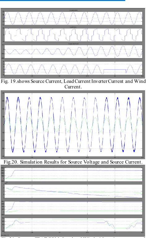
Fig. 19.shows Source Current, Load Current Inverter Current and Wind Current.
Fig.20. Simulation Results for Source Voltage and Source Current.
Fig.22.T HD for Source Current without ST AT COM.
Fig.23.T HD for Source Current with ST AT COM for Hybrid Fuzzy Logic Control.
VII.CONCLUSION
Flexible AC Transmission System (FACTS) is one aspect of the power electronics revolution that happened in all areas of electric energy. A novel VLSI based hybrid fuzzy logic controller was designed to improve the transient stability of the proposed control system due to the inherent vagaries of nature. The proposed system was simulated using Simulink blocks and Modeling. The proposed hybrid fuzzy outputs were measured and the performance of the control system studied. It is found the proposed system was able to recover from most of the faults as in the case of STATCOM. However the transients in the proposed system are much lower than the STATCOM based system.
REFERENCES
[1] Wind Integration: International Experience, WP2: Review of Grid Codes, October 2011
[2] M. T sili and S. Papathanassiou, “A review of grid code technical requirements for wind farms,” Renewable Power Generation, IET , vol. 3, no. 3, pp. 308–332, Sept. 2009.
[3] M. Sedighizadeh and M. M. Hosseini , “INVEST IGAT ION AND COMPARISON OF USING SVC, ST AT COM AND DBR’s IMPACT ON WIND FARM INT EGRAT ION, International Journal of Engineering and Applied Sciences (IJEAS),Vol.2, Issue 4(2010)38-54. [4] CH. AppalaNarayana, D.V.N.Ananth, K.D.Syam Prasad, CH.Saibabu, S.SaiKiran, T . PapiNaidu, “Application of ST ATCOM for
T ransient Stability Improvement and Performance Enhancement for a Wind T urbine Based Induction Generator”, International Journal of Soft Computing and Engineering (IJSCE) ISSN: 2231-2307, Volume-2, Issue-6, January 2013.
[5] G. Elsady, Y. A. Mobarak, and A-R Youssef, “ST AT COM for Improved Dynamic Performance of Wind Farms in Power Grid”, Proceedings of the 14th International Middle East Power Systems Conference (MEPCON’10), Cairo University, Egypt, December 19-21, 2010, Paper ID 207.
[6] Paulo Fischer de Toledo, Hailian Xie,” T OPIC 7: WIND FARM IN WEAK GRIDS COMPENSAT ED WIT H ST AT COM”, KT H, Kungl T ekniska Högskolan, EME department Teknikringen 33-35, Stockholm, Sweden.
[7] M. Jahangir Hossain, Hemanshu R. Pota, Valeri A. Ugrinovskii and Rodrigo A. Ramos,”Simultaneous ST ATCOM and Pitch Angle Control for Improved LVRT Capability of Fixed-Speed Wind T urbines”, IEEE T RANSACT IONS ON SUST AINABLE ENERGY, VOL. 1, NO. 3, OCT OBER 2010.
[8] X.P. Zhang, C. Rehtanz, B. Pal, “Flexible AC T ransmission Systems: Modeling and Control”, ISBN-13 978-3-540-30606-1, Springer-Verlag Berlin Heidelberg 2006.
[9] O. Noureldeen ,”Characteristics of Fixed Speed Wind T urbines Interconnected Grid during Wind Speed Variations”, 13th Middle East power systems conference MEPCON, 2009 Assuit University, Egypt, December 20-23, 2009.
[10] F.G.R. de campos and A.A. Jr. penteado, ”Wind Energy generation Simulation with asynchronous generator connected to ENERSUL distribution System”, IEEE/PES T ransmission and Distribution conference and Exposition, Latin America, pp. 149-154, 2004.
Author’s Profile:
VADLA SURENDRA CHARY received B.T ech from P.indra reddy memorial engineering college in the year of 2014 and now pursuing M.T ech in the stream of Power Systems at Narsimha Reddy Engineering college.
NARESH BANDI received B.T ech degree from ramappa Engineering college (JNTUH) in the year 2006 and received M.Tech in the stream of Power Electronics at P.indhra reddy memorial college of Engineering (JNTUH) in the year 2013. Currently working as a Assistant Professor in Narsimha Reddy Engineering College for one year. And his areas of interest are Applications of Power electronics in “Power Systems& Electrical machines”.