Dynamic Modelling and Simulation of Five
Phase Induction Motor
Mitesh B. Astik
1Assistant Professor, Dept. of EE, A.D. Patel Institute of Technology, New V.V. Nagar, Anand, Gujarat, India1
ABSTRACT
:
In this paper, a dynamic modelling of five-phase induction motor is described in a step by step approach. A dq model based on transformation theory for five-phase induction machine is presented. A detailed implementation of an indirect-type five-phase field oriented control including the hysteresis-type pulse width modulation (PWM) current regulator is described. Simulations have been carried out for different load conditions.
KEYWORDS
:
Dynamic Model, Five-Phase Induction Motor, Indirect Vector Control.I.INTRODUCTION
The advantages of five-phase machines are found over three-phase machines such as an increase in current per phase without the need to increase the phase voltage, reduction in amplitude and increase in frequency of pulsating torques, fault tolerance, stability and lower current ripple [1]. It has also been shown that increasing the number of phases can result in an increase in the torque/ampere relation for the same volume machines [2]-[4]. Hence the analysis, design and application of machines with high phase numbers require adequate mathematical models to be established, through which their performance and advantages can be assessed.
S. Boora et. al. [5] presented paper on dynamic d-q axis model of three- phase asynchronous motor in synchronously rotating frame. In this paper, authors have transferred three-phase voltage in to two-phase voltage axis using dq transformation. S. Gupta and S. Wadhwani [6] discussed modeling of induction motor using synchronously rotating reference frame. Mathematical modeling of three-phase induction motor was discussed in this paper. The steady-state and transient response of the motor have shown with varying load on motor. Five-phase induction motor performance under symmetrical and asymmetrical connection have discussed in [7]-[8]. In these papers, authors have mentioned that if one or two legs of the inverter are open circuited then also motor work satisfactory with the increment of fundamental and third harmonic currents. Simulink induction machine models are available in the literature [9]-[10], but they appear to be black-boxes with no internal details.
In this paper each block solves one of the model equations. The necessary differential equations describing the performance of five-phase induction machines in d-q frame of reference based on transformation theory are presented in this paper. A detailed implementation of an indirect-type five-phase field-orientation control including the hysteresis type of PWM current regulator is illustrated [11]. Simulations have been carried out for different load conditions.
II.DYNAMICMODELLINGOFFIVE-PHASEINDUCTIONMOTOR
The five-phase stationary reference frame variables are transformed into two-phase stationary reference frame variables and then transform these variables into synchronously rotating reference frame and vice-versa. The voltage as-bs-cs-ds-es can be ras-bs-cs-ds-esolved into Vds and Vqs components and can be represented in the matrix form using (1).
es ds cs bs as
ns qs ds
V V V V V
2
2 4
4 4 -2
-4 -2
-cos
5 2
V V V
2 1
5 sin
5 cos
2 1
5 sin
5 cos
2 1 2
1 2
1
5 sin
5 sin
sin
5 cos
5 cos
es ds cs bs as ns qs ds I I I I I 2 2 4 4 4 -2 -4 -2 -cos 5 2 I I I 2 1 5 sin 5 cos 2 1 5 sin 5 cos 2 1 2 1 2 1 5 sin 5 sin sin 5 cos 5 cos (2)where, Vas, Vbs, Vcs, Vds and Ves are stator phase voltages. Vds and Vqsare the d
s and qs axis stator fundamental voltages
respectively. Vnsis the zero sequence component of the stator. It is convenient to set
0, so that the qs axis is aligned with the as-axis. Ignoring the zero sequence components, the transformation relations can be simplified using (3)-(4).
V V cos(-2 5) V cos(-4 5) V cos( 4 5) V cos(2 5)
Vqs a b c d e
5 2
(3)
V sin(-2 5) V sin(-4 5) V sin( 4 5) V sin(2 5)
Vds b c d e
5 2
(4)
The two-phase ds-qs winding are transformed into the hypothetical windings mounted on the de-qe axis, which rotate at synchronous speed e with respect to the ds-qs axis and the angle e et. the voltage on the ds-qs axis can be converted into the de-qe frame as follows[12]-[13]:
ds qs de qe V V cos V V cos sin sin (5)
For the two-phase machine, we need to represent both ds-qs and dr-qr circuit and their variables in a synchronously rotating de-qe frame. The de-qe frame voltage expressions are:
ds e qs qs s qs dt d i R
V ; ds s ds ds- e qs
dt d i R
V (6)
dr e qr qr r qr - dt d i R
V ; r dr dr- e qr
dt d i
R
dr
V (7)
Since the rotor actually moves at speedr, the dq axes fixed on the rotor which moves at a speed of (e- r) relative to the synchronously rotating frame. The flux linkage expressions for dq frame are:
) qr i qs (i m X qs i ls X qs
b
qs
F ; Fqr =ωbΨqr = Xlriqr +Xm(iqs + iqr) (8)
) dr i ds (i m X ds i ls X ds
b
ds
F ; Fdr =ωbΨdr = Xlridr +Xm(ids + idr) (9)
) qr i qs (i m X qm
b
qm
F ; Fdmbdm Xm(ids idr) (10)
where XlsbLls,Xlr bLlr andXmbLm (11)
By substituting (8)-(9) in (6)-(7), the voltage expressions can be written as:
ds F b e qs F dt d b 1 qs i s R qs
V ;
qs F b e -ds F dt d b 1 ds i s R ds
V (12)
dr F b ) r -e ( qr F dt d b 1 qr i r R 0
; Fqr
b ) r -e ( -dr F dt d b 1 dr i r R 0
By substituting (11) in (8)-(9), the flux linkage equations can be written as
(LlsLm)iqs Lmiqr
b qs
F
;
(LlsLm)idsLmidr
b ds
F
(14)
(Llr Lm)iqr Lmiqs
b qr
F
;
(Llr Lm)idrLmids
b dr
F
(15)
By substituting (14) in (12), we get (16)-(17).
ls m ds m dr
e qs s qr m qs qs m ls i L i ) L (L -i R -dt i d L -V dt i ) L (L d
(16)
qr s qs e ls m ds m drm qs m ls
qs - R i - (L L )i L i
dt i d L -V L L 1 i (17)
Similarly, we can write remaining current equations as given in (18)-(20).
dr s ds e ls m qs m qrm ds m ls
ds - R i (L L )i L i
dt i d L -V L L 1 i (18)
qs r qr e r lr m dr m dsm m lr
qr - R i - ( - ) (L L )i L i
dt i d L L L 1
i
(19)
ds r dr e r lr m qr m qsm m lr
dr -R i ( - ) (L L )i L i
dt i d L -L L 1
i
(20)
Now, the flux linkage expressions in terms of currents can be written as follows:
) i (i L i
Lls qs qs qr
qs m ; dsLlsidsLm(idsidr) (21)
) i (i L i
Llr qr qs qr
qr m ; dr LlridrLm(idsidr) (22)
) i (i L
qs qr
qm m ; dm Lm(idsidr) (23)
Now, the torque expression can be written as follows:
( i - i )L L L 2 P 2 5 ds qr qs dr lr m
m
e
T (24)
The speed and torque are given by the following relation:
L e r B T -T
dt r
d
J (25)
III.CONTROLLEROFFIVE-PHASEINDUCTION-MOTOR(INDIRECTVECTORCONTROLMETHOD)
Fig. 1 Complete block diagram of indirect vector control method
A. dq axis rotating current:
The five-phase currents can be resolved into ids and iqs components and can be represented in the matrix form from (2).
B. Flux Phir:
The flux produced in the stator winding is given by
1 Ts
I Lm ds*
Phir (26)
where T = Lr / Rr.
C. Rotor position:
Now, the rotor position
r m
(27)where,
mmechanical speed and ωr isrotor frequency (rad/sec)
L Phir
R i L
r r qs m
r
(28)
D. Fundamental reference torque (Te*):
The fundamental reference torque (Te*) is obtained by using proportional plus integral (PI) controller whose input is the
error between the actual and reference speed.
E. Synchronous rotating dq-axis current:
The dq-axis synchronous rotating currents are given by
m d
L Phir
ds
i ;
Phir T L
L P 2 5
2 e
m q r
qs
i (29)
where phir* is constant flux, ids and iqs are d and q axis synchronous rotating reference currents respectively.
F. Rotating to stationary abcde conversion:
G. Hysteresis Control PWM:
With the use of hysteresis control PWM method, actual and reference five-phase currents are compared and the gate pulses are generated to control the five-phase induction motor [5]. Fig. 2 shows the block diagram of hysteresis control PWM.
Fig. 2 Block diagram of Hysteresis Control PWM
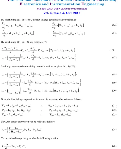
Fig. 3 shows the simulation of five-phase voltages from the gate pulses. These five-phase voltages applied to the stator winding of five-phase induction motor.
Fig. 3 Five-phase voltages from the gate pulses
IV. SIMULATION RESULTS AND DISCUSSIONS
Five-phase induction motor is simulated in MATLAB software for different load conditions. No-load speed, current and torque waveforms are shown in Fig. 4, 6 and 8 respectively. Load torque of 1 Nm and 5 Nm are applied to the motor and the speed, current and torque responses of the motor are shown in Fig. 5, 7 and 9 respectively.
Fig. 4 shows the dynamic simulation result of no-load speed of five-phase induction motor.
Fig. 5 (a) and (b) show the dynamic simulation result of speed at load torque TL = 1 Nm and TL = 5 Nm respectively.
Fig. 5 Speed response at (a) TL = 1 Nm (b) TL = 5 Nm
It is observed from Fig. 4 and 5 that the motor achieve rated speed of 160 rad/sec at around 1 sec and also achieve steady state speed for different load with approximate zero steady state error. The speed of five-phase induction motor is 160 rad/sec for the entire load and the response of the motor is under damped.
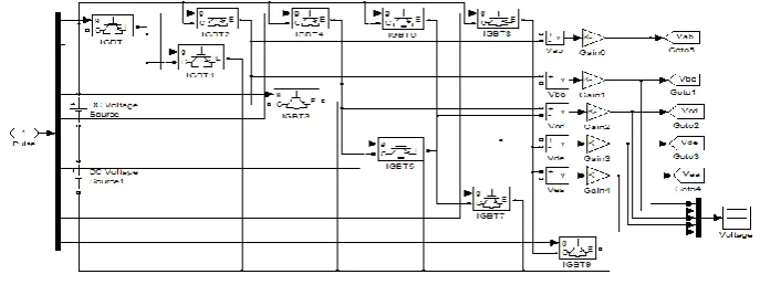
Fig. 6 shows the dynamic simulation result of no-load torque of five-phase induction motor.
Fig. 6 No-load torque
Fig. 7 (a) and (b) show the dynamic simulation result of torque response at load torque TL = 1 Nm and TL = 5 Nm
respectively.
Fig. 7 Torque response at (a) TL = 1 Nm (b) TL = 5 Nm
From Figs. 6 and 7, we can see that the maximum torque developed in five-phase induction motor is varied with the load torque variations but these variations are very less. The steady state torque is almost same for entire load.
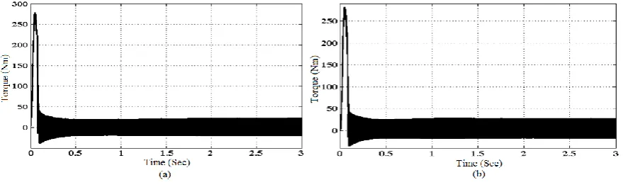
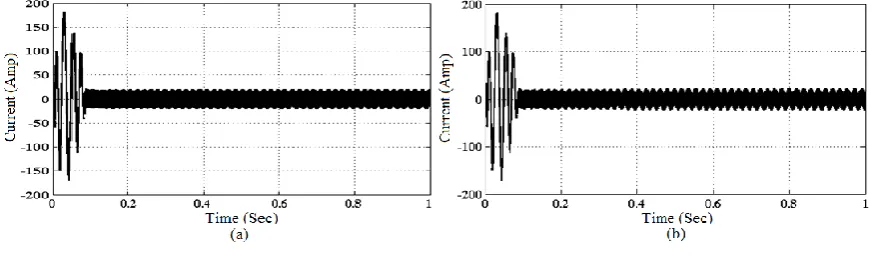
Fig. 8 No-load current
Fig. 9 (a) and (b) show the dynamic simulation result of current response at load torque TL = 1 N-m and TL = 5 Nm
respectively.
Fig. 9 Current response at (a) TL = 1 Nm (b) TL = 5 Nm
The variations in transient as well as steady state current are less with the change in load torque of five-phase induction motor.
The effect of load torque variations in motor performance can be seen in Table 1.
Table-1 comparative simulation results
Table 1shows the comparative simulation results when different load torque applied to five-phase induction motor. The steady state speed of the motor is constant for entire load. The variations in maximum torque and current are less during load torque variations.
V.CONCLUSION
The speed of five-phase induction motor can be controlled using different types of methods such as V/ f method, vector control method etc. The dynamic modeling of five-phase induction motor is done in step by step approach in this paper. The speed control of the five-phase induction motor is achieved by indirect vector control method. From the simulation result, we can conclude that the actual speed successfully tracks the reference speed in both transient as well
Load (Nm)
Speed (rad/sec)
Maximum Torque (Nm)
Transient Current (A)
TL = 0 160.00 277.84 180.52
TL = 1 160.00 278.74 180.79
current are very less in both the transient as well as steady state part even if change in load torque. The simulation results prove the effectiveness of the controller design.
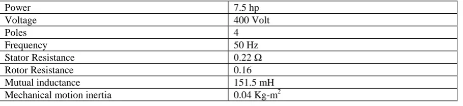
APPENDIX
Table - 2 parameters of five-phase induction motor
Power 7.5 hp
Voltage 400 Volt
Poles 4
Frequency 50 Hz
Stator Resistance 0.22 Ω
Rotor Resistance 0.16
Mutual inductance 151.5 mH
Mechanical motion inertia 0.04 Kg-m2
REFERENCES
[1] H. Xu, H.A. Toliyat and L.J. Peterson, “Modeling and Control of Five-Phase Induction Motor under Asymmetrical Fault Conditions”, Proceedings of the Third Naval Symposium on Electric Machines, Philadelphia, pp. 4-7, 2000.
[2] H.A. Toliyat, “Analysis and Simulation of Five-phase Variable Speed Induction-Motor Drives under Asymmetrical Connections”, IEEE Transaction on Power Electronics, Vol. 13, No. 4, pp. 748-756, 1998.
[3] H.A. Toliyat, T.A. Lipo and J.C. White, “Analysis of a concentrated winding Induction Machine for adjustable Speed Drive Application-part I (Motor Analysis)”, IEEE Transaction on Energy Conversion, Vol. 6, No. 4, pp. 679-683, 1991.
[4] H.A. Toliyat, T.A. Lipo and J.C. White, “Analysis of a concentrated winding Induction Machine for adjustable Speed Drive Application-part II (Motor Design and Performance)”, IEEE Transaction on Energy Conversion, Vol. 6, No. 4, pp. 684- 692, 1991.
[5] S. Boora, S.K Agarwal and K.S Sandhu, “Dynamic d-q Axis Modeling of Three-Phase Asynchronous Machine Using Matlab”, International Journal of Advanced Research in Electrical, Electronics and Instrumentation Engineering (IJAREEIE), Vol. 2, No. 8, pp. 3942-3951, Aug. 2013.
[6] S. Gupta and S. Wadhwani, “Dynamic Modeling of Induction Motor Using Rotor Rotating Reference Frame”, International Journal of Advanced Research in Electrical, Electronics and Instrumentation Engineering (IJAREEIE), Vol. 3, No. 6, pp. 10132-10140, June 2014. [7] M.B. Astik and D.R. Mehta, “dq Modeling and Control of Five-phase Induction Motor under Asymmetrical Connections using MATLAB
Simulation”, NUCONE – 2007, Nirma University, pp. 13-17, 2007.
[8] K. Thiyagarajah and S. Mythili, “Vector Control of Five-Phase Induction Motor under Asymmetrical Connection”, International Journal of Electrical and Power Engineering, Vol. 2, No. 5, pp. 288-292, 2008
[9] Atif Iqbal, Sk Moin Ahmed, Md Arif Khan, Mohd. Rizwan Khan and Haitham Abu-Rub, “Modeling, Simulation and Implementation of a Five-Phase Induction Motor Drive System”, Joint International Conference on Power Electronics, Drives and Energy Systems (PEDES-2010), Power India, pp. 1-6, 2010.
[10] Lu´is Alberto Pereira, C´esar Cataldo Scharlau, Lu´is Fernando Alves Pereira and Jos´e Felipe Haffner, “General Model of a Five-Phase Induction Machine Allowing for harmonics in the Air Gap Field”, IEEE Transaction on Energy Conversion, Vol. 21, No. 4, pp. 891-899, 2006.
[11] Burak Ozpineci and Leon M. Tolbert, “Simulink Implementation of Induction Machine Model – A Modular Approach”, Electric Machines and Drives Conference, IEMDC'03. IEEE International, Vol. 2, pp. 728-734, 2003.
[12] B.K. Bose, Modern Power Electronics and AC Drives, Pearson Education Pvt. Ltd., Delhi, India, 3rd edition, 2003.