A Performance Analysis of MSA using
Various Excitation Techniques
R.Malathy1, R.Maheswari2
Assistant Professor, Dept. of ECE, Agni College of Technology, Chennai, Tamilnadu, India1 Assistant Professor, Dept. of ECE, Agni College of Technology, Chennai, Tamilnadu, India 2
ABSTRACT: Micro strip antennas (MSA) in antenna technology appeared relatively late, but in recent years has been a very large development of the design of these antennas and the huge interest in their capabilities. MSA has more advantages and better prospects. This paper describes various excitation techniques and performance of different parameters. Performance of the antenna mainly depends on the dielectric constant or permittivity of a substrate .The substrate which has a low dielectric constant will give better performance than the substrate which has a high dielectric constant. Loss tangent or dissipation factor also plays a part in antenna performance. Substrate materials play an important role in antenna design, production and finished product performance This survey suggest dielectric material like Air, RTduroid, Benzocyclobuten and Taconic TLC can be used to fabricate micro strip patch antenna in order to give better performance.
KEYWORDS: Micro strip antenna, Feeding techniques, Dielectric substrate, Permittivity
I. INTRODUCTION
Although the field of antenna engineering has a history over years it still remains as described in [2] “a vibrant field which is bursting with activity, and is likely to remain so in the foreseeable future.” The statement has relevance even now. The scope of antenna design moves into new pastures of technology. An antenna is the primary component in a wireless communication system. Antenna is a transducer designed to transmit or receive electromagnetic waves. When a signal is fed into an antenna, the antenna will emit radiation distributed in space in a certain way.There are different types of antenna and depending upon the applications, the properties of an antenna including physical structure varies. Every system demands for compact and efficient components to be embedded with it. Micro strip patch antenna is such a component which is so popular by its compact size particularly in the frequency range of 1 to 6 GHz.
II. MICROSTRIP PATCH ANTENNA
The concept of the Micro strip antenna (MSA) was first proposed in 1953 by Deschamps. However, practical antennas were developed by Munson and Howell in the 1970s. Often micro strip antennas are also referred to as micro strip patch antennas, or simply patch antennas. The unique property of the micro strip patch antenna is its two- dimensional structure [3].Micro strip antennas have several advantages over conventional microwave antenna and therefore are widely used in many practical applications. Micro strip antennas in its simplest configuration are shown in Fig1.
It consists of a radiating patch on one side of dielectric substrate (Єr≤10), which has a ground plane on other side. A micro strip patch antenna (MSA) consists of a conducting patch of any planar or nonplanar geometry on one side of a dielectric substrate with a ground plane on other side. It is a popular printed resonant antenna for narrow-band microwave wireless links that require semi-hemispherical coverage. Due to its planar configuration and ease of integration with micro strip technology, the micro strip patch antenna has been heavily studied and is often used as elements for an array. The rectangular and circular patches are the basic and most commonly used micro strip antennas. These patches are used for the simplest and the most demanding applications. Rectangular geometries are separable in nature and their analysis is also simple. The circular patch antenna has the advantage of their radiation.
Micro strip antennas are characterized by a larger number of physical parameters than conventional microwave antennas. They can be designed to have many geometrical shapes and dimensions [4]. All micro strip antennas can be divided into four basic categories:
1. Printed slot antennas 2. Micro strip dipoles 3. Micro strip patch antennas
4. Micro strip Travelling-wave antennas
2.1.1 Characteristics of Patch:
The following Table 1. Show the characteristics of the different micro strip antennas.
S.no Characteristics Micro strip patch antenna
Printed slot antenna Micro strip dipole antenna
1. Profile Thin Thin Thin
2. Fabrication Very easy Easy Easy
3. Polaraization Both linear & circular Both linear & circular Both linear
4. Dual frequency
operation
Possible Possible Possible
5. Shape flexibility Any shape Mostly rectangular & circular shapes
Mostly rectangular & triangular shapes
6. Spurious Radiation Exists Exists Exists
7. Bandwidth 2-50% 5-30% Approximately 30%
Table.1. Characteristics of micro strip patch antennas
III. ANALYSIS OF EXCITATION TECHNIQUES.
Excitation techniques are also commonly known as Feeding methods. Feeding of the micro strip patch antennas can be done by a variety of methods. These methods can be classified into two categories- contacting and non-contacting. In the contacting method, the RF power is fed directly to the radiating patch using a connecting element such as a micro strip line. In the non-contacting scheme, electromagnetic field coupling is done to transfer power between the micro strip line and the radiating patch. The four most popular feed techniques used are the micro strip line, coaxial probe; both contacting schemes; aperture coupling and proximity coupling; both non-contacting schemes[1].
3.1 Micro strip Line Feed
Fig. 3.1 Microstrip line feed and its circuit diagram
The purpose of the inset cut in the patch is to match the impedance of the feed line to the patch without the need for any additional matching element. This can be achieved by properly controlling the inset position. Hence this is an easy feeding scheme, since it provides ease of fabrication and simplicity in modeling as well as impedance matching. However as the thickness of the dielectric substrate being used, increases, surface waves and spurious feed radiation also increases, which hampers the bandwidth of the antenna. The feed radiation also leads to undesired cross polarized radiation.
3.2 Coaxial Feed
The Coaxial feed or probe feed is a very common technique used for feeding micro strip patch antennas. As seen from Fig.3.2, the inner conductor of the coaxial connector extends through the dielectric and is soldered to the radiating patch, while the outer conductor is connected to the ground plane.
Fig.3.2.Probe fed micro strip patch antenna and its circuit diagram
3.3Aperture Coupled Feed
In this type of feed technique, the radiating patch and the micro strip feed line are separated by the ground plane as shown in Fig.3.3. Coupling between the patch and the feed line is made through a slot or an aperture in the ground
plane.
Fig.3.3 Aperture-coupled feed and its Circuit diagram
The coupling aperture is usually centered under the patch, leading to lower cross polarization due to symmetry of the configuration. The amount of coupling from the feed line to the patch is determined by the shape, size and location of the aperture. Since the ground plane separates the patch and the feed line, spurious radiation is minimized. Generally, a high dielectric material is used for bottom substrate and a thick, low dielectric constant material is used for the top substrate to optimize radiation from the patch. The major disadvantage of this feed technique is that it is difficult to fabricate due to multiple layers, which also increases the antenna thickness. This feeding scheme also provides narrow bandwidth.
3.4 Proximity Coupled Feed
This type of feed technique is also called as the electromagnetic coupling scheme. As shown in Figure3.4, two dielectric substrates are used such that the feed line is between the two substrates and the radiating patch is on top of the upper substrate. The main advantage of this feed technique is that it eliminates spurious feed radiation and provides very high bandwidth (as high as 13%), due to overall increase in the thickness of the micro strip patch antenna. This scheme also provides choices between two different dielectric media, one for the patch and one for the feed line to optimize the individual performances.
Fig.3.4 Proximity-coupled Feed and its circuit diagram
IV. COMPARISON OF DIFFERENT EXCITATION TECHNIQUES
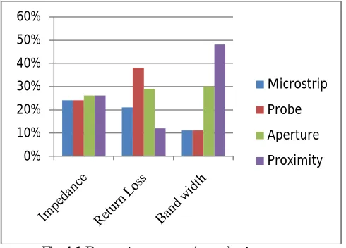
A micro strip patch antenna excited by different excitation techniques gives different bandwidth, different gain and different efficiency etc. We can obtain the approximate result of Return Loss, Bandwidth and Impedance of all feeding techniques .Those feeding techniques are Micro strip Line, Probe, Proximity and Aperture which describe the comparison of Return Loss, Bandwidth and Impedance .These feeding techniques are given below in Table 2.
Characteristics Micro strip feed Coaxial feed Proximity feed Aperture feed
Return Loss Less More More Less
Resonant frequency
More Less Highest Least
VSWR Lower than 1.5 Between 1.4 -1.8 Less than 1.23 Approx equal to 2 Spuriousfeed
radiation
More More More More
Polaraization purity
Poor Poor Poor Excellent
Easeof fabrication Simple Soldering and Drilling needed
Alignment Required
Alignment Required
Reliability Better Poor due soldering Good Good
Impedance matching
Easy Easy Easy Easy
Bandwidth 2-5% 2-5% 13% 21%
Table 2: Comparison of different feeding techniques.
The maximum bandwidth can be achieved by Proximity feed coupling and also it eliminates spurious feed radiation. Both Proximity feed coupling and Aperture feed coupling gives the best impedance matching and radiation efficiency.Typically matching is performed by controlling the width of the feed line and the length of the slot.
Fig 4.1 Parameters comparison chart
V. DIELECTRIC SUBSTRATES
Substrate materials play an important role in antenna design, production and finished product performance. A simple method that can be employed to modify the different properties of the antenna is by changing the substrate; as height and dielectric constant of the substrate influence the antenna properties. The substrate in microstrip antenna is primarily required for giving mechanical strength to antenna [4]. An intelligent decision has to be taken while selecting a
0% 10% 20% 30% 40% 50% 60%
Microstrip
Probe
Aperture
substrate so as to satisfy both electrical and mechanical requirement for the antenna. Some properties of different dielectric substrates are
Material Dielectric constant Loss tangent
Air 1 0.0
Teflon (PTFE) 2.0 – 2.1 0.00028
RT Duroid 2.2 0.0004
Butyl rubber 2.35 0.001
Polystyrene 2.5 – 2.6 0.00033
Benzocyclobuten 2.6 0.00
Taconic TLC 3.2 0.002
Table 3: Properties of different dielectric substrates
The substrate properties that are taken into consideration while selecting a dielectric include: dielectric constant and loss tangent and their variation with temperature and frequency, homogeneity, dimensional stability with processing and temperature, humidity and aging.
VI. CONCLUSION
Micro strip patch antennas are used for many applications, especially in wireless communication and in satellite communication. The MSA has proved to be an excellent radiator .Performance of bandwidth can be enhanced for MSA by choosing low permittivity dielectric material because bandwidth is inversely proportional to permittivity. This survey suggest dielectric material like air, RTduroid, Benzocyclobuten and Taconic TLC can be used to fabricate micro strip patch antenna in order to give better performance.
REFERENCES
[1] Balanis C.A., “Antenna Theory: Analysis and Design”, John Wiley &Sons, Inc, 1997.
[2] David M. Pozar, “Micro strip Antennas”, Proceedings of the IEEE, Vol. 80, No 1, pp. 79-91, January 1992.
[3] Gary Breed, “The Fundamentals of Patch Antenna Design and Performance”, High Frequency Electronics, pp. 48-51, March 2009. [4]. Ramesh Garg, Prakash Bartia, Inder Bahl, Apisak Ittipiboon, ‘’Micro strip Antenna Design Handbook’’, 2001, pp 1‐68, 253‐316 .
[5] R. Yang, Y. Xie, P. Wang and L. Li, “Micro strip Antennas with Left-Handed Materials Substrates,”Journal of Electromagnetic Waves and Applications,