Development of a Microcontrolled System for
DC Motor Control Using MATLAB/Simulink
Software
B. M. Shimada1, L. Niro2, M.F.Mollon3, E.H.Kaneko4, W. S. Chaves5, M.A.F.Montezuma6
Master in Mechanical Engineering, Federal University of Technology – Paraná, CornélioProcópio, Paraná, Brazil1
Substitute Professor, Federal University of Technology – Paraná, CornélioProcópio, Paraná, Brazil2
Graduated Student, Federal University of Technology – Paraná, CornélioProcópio, Paraná, Brazil3,4,5
Professor, Federal University of Technology – Paraná, CornélioProcópio, Paraná, Brazil6
ABSTRACT:This paper presents a control system for DC motor based on Microchip dsPIC30F2010 microcontroller.
This device is responsible for mediating the communication between MATLAB/Simulink software and the DC motor didactic kit. This educational platform contains an incremental encoder for reading the angular position of the motor, besides a power drive to send the control signal to it. In this way, the microcontroller acts as an acquisition board, in which it calculates the motor speed and sends it to MATLAB/Simulink via RS-232 serial communication.On the other hand, MATLAB/Simulink is responsible for sending the control signals to the microcontroller that will be applied on the motor power drive. In addition, the educational kit has a generator coupled to the motor axis to simulate mechanical disturbances or loads, in which its intensity is also defined and sent to the microcontroller via the MATLAB/Simulink interface. In this context, the implemented structure turns easy the changing of the control technique without reprograming the microcontroller, and allows the implementation of various control techniques, such as classic, modern and unconventional through the programming offered by MATLAB/Simulink. However, for the correct integration between the Hardware/Software interface, two specific blocks were developed in the Simulink, such as the block for inputting motor speed and current data, as well as the data output block for sending control signal, disturbance and motor's direction of rotation. Finally, as a system validation, a technique based on the Proportional-Integral Derivative (PID) controller was implemented to control the motor's kit. In addition, a Fuzzy Logic Controller (FLC) design was presented as an alternative control technique that can be performed through the developed Hardware/Software interface. The results in relation to acquisition of data for the PID control were satisfactory.
KEYWORDS:Hardware-in-the-loop, Control Systems, Serial Communication.
I. INTRODUCTION
The direct current (DC) motor is a power actuating device that converts DC power into rotating mechanical energy [1]. This device has as main characteristics, the high torque at start and at low rotations, wide variation of speed, relative simplicity of its drive systems for position and speed control, when compared to the machines of alternating current. Due to these characteristics, DC motor systems are still used in several control applications, including robotic manipulators, tape conveyors, machine tools, disk drives, among others [2].
Generally, the DC motor drive that are currently marketed have motor control structures for industrial purposes, resulting in complex, sophisticated and costly equipment. It makes difficult to introduce and study new technologies to improve performance and implementation of new control techniques [3].
Based on the difficulties encountered in the study of digital control techniques, the objective of this work is to build an educational kit for closed-loop speed control of a DC motor. The main proposal was to develop a low-cost solution for students and university researchers to implement digital control systems in real devices.
The didactic kit has as data acquisition system, the dsPIC30F2010 microcontroller, and as a graphical user interface, the MATLAB/Simulink software, which is used for implementation and processing of the control algorithm.
The MATLAB/Simulink interface allows real-time visualization of the control variables, such as: motor speed and current, in addition to adjustments in the control parameters related tovoltage applied to the motor, direction of rotation and load variation in the motor shaft. This allows the analysis of control systems and behavior of a DC motor without reprograming the microcontroller in C or Assembly language, which makes it possible to implement the PID control that will be demonstrated in this article, besides allowing to implement other techniques of classic, modern or unconventional control through the programming facilities offered by MATLAB/Simulink. The FLC proposed in this article is an example of alternative technique that can be performed with the developed Hardware/Software interface.
II.DEVELOPED EDUCATIONAL KIT
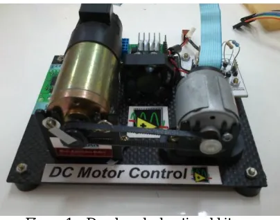
The kit used to perform the experiments was developed at the Laboratory of Automated Systems and Control (LaSisC), at the Federal University of Technology – Paraná. This educational system contains a Pitman DC motor, with maximum operating voltage of 19.1V and maximum rotation of 10,000 rpm. In addition, an incremental encoder for position and velocity reading, model HEDS-5310 of the Avago brand, which has 512 lines and 3 channels, was coupled to the DC motor axis. To reproduce the mechanical loads and/or disturbances in the motor shaft, a generator was coupled to it by a belt, as shown in Figure 1.
Figure 1 – Developed educational kit
(a) (b)
Figure 2 – Educational kit: (a) developed electronics boards; (b) system mounted for experiments.
The microcontroller used in this project is a device that combines the performance of digital signal processors (DSP), coupled with the programming simplicity of a common microcontroller, whose the operating capacity isup to 30 million instructions per second (MIPS), besides having some characteristics such as: an input for reading encoders in quadrature to obtain the angular position, module for PWM generation (Pulse-Width Modulation) via hardware, 27 interrupt sources with 8 levels and 2 ports for Universal Asynchronous Receiver/Transmitter (UART) communications [4].
The L298 power drive is capable of providing operating voltages up to 46V with 4A currents, having as configuration the control of 4 quadrants arranged in the form of an H bridge, which allows the two-way motor rotation through digital drives in their logic gates [5]. In addition, an FTDI FT232RL USB/Serial converter chip was used in the electronic board to perform the communication of the microcontroller with the computer. This converter virtualizes a serial port in the operating system of the computer, being recognized as a serial port, even though it is connected to a USB port. In this way,data can be treated as a standard serial communication in MATLAB/Simulink software.
The resistances connected to the generator were used to generate mechanical loads in the DC motor, in order to test the efficiency of the control systems. Four different electrical resistances were used, which can be combined to generate different intensities of mechanical load on the motor shaft. These loads can be combined through the commands sent by the graphical interface.
V.PROGRAMMING THE HARDWARE/SOFTWARE INTERFACE
To control the DC motor, it was necessary to develop an interface between the educational kit and the MATLAB/Simulink software. This Hardware/Software interface was implemented by programming a specific firmware in the microcontroller based on the C language. This firmware was responsible for calculating the current of the motor through an analog signal sent by the power drive, besides calculating the motor speed by reading the encoder. The calculated speed and motor current are converted into digital data and sent via serial communication to the MATLAB/Simulink software. With the data sent, the control system desired by the operator is implemented, and then the processed data is sent back to the microcontroller through the serial communication. These data are related to the PWM duty cycle values, the motor’s direction of rotation, motor enable and generator load value.
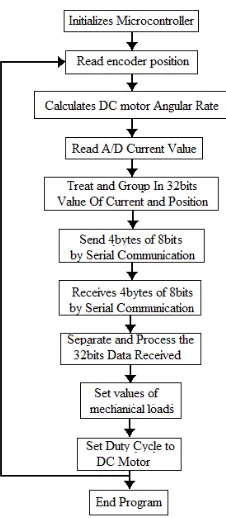
the schematic of the Hardware/Software interface for controlling the DC motor. In Figure 4 is presented the flowchart of the Hardware/Software interface routines implemented in the microcontroller.
The routine implemented in the microcontroller is started by configuring the basic operating parameters of the dsPIC30F2010. After this step, the values for encoder position are read through the QEI (Quadrature Encoder Interface) module and for motor current through an A/D (Analogic/Digital) converter. Then, by the position of the encoder is calculated the motor speed, and these parameters are grouped into a variable of 32 bits, that later is sent through serial communication in the form of 4 bytes with 8 bits in sequence, since the serial communication gives the maximum sending of 8 bits at a time.
Figure 3 - Block diagram for DC motor control
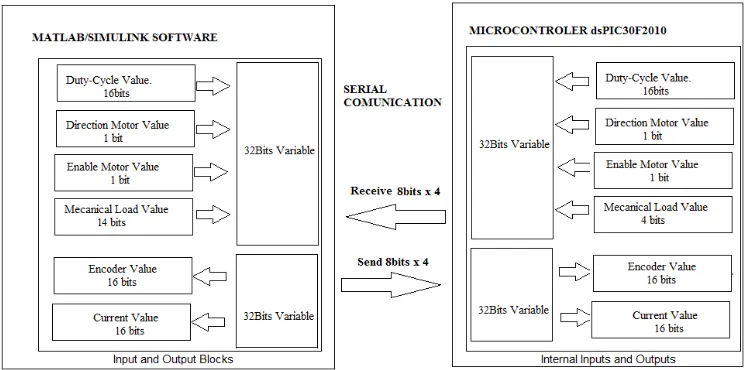
After sending the data to the computer, the values are processed by a control system implemented in the Simulink and its results are returned again in the 32 bits form, being sent in 4 bytes of 8 bits for reception in the microcontroller. With the data received, they are grouped to form a 32-bit variable in the microcontroller, and from this variable the parameter values are properly separated by the masking technique. Once all parameters received by the serial communication have been processed and separated, the PWM duty cycle value, motor direction and load values are defined on the microcontroller for the motordrive operation and appliance of the mechanical loading in the experiment kit. Figure 5 shows the schematic of the communication and data handling previously described.
Figure 5 – Schematic of serial communication and data processing.
VI. MATLAB/SIMULINK PROGRAMMING
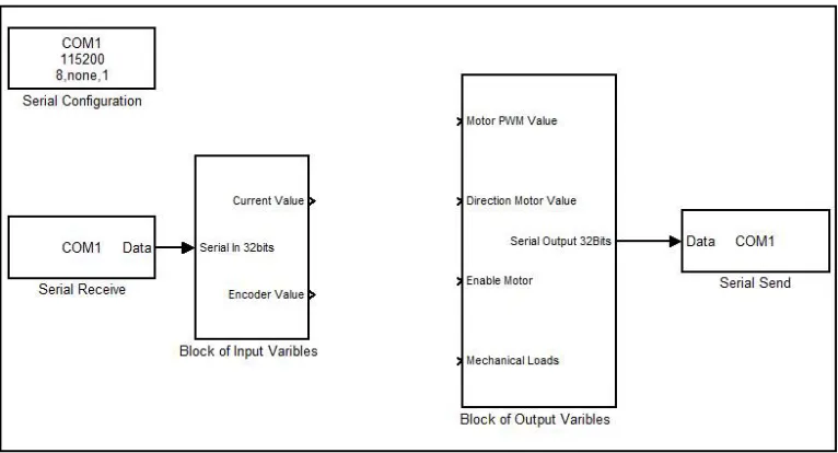
Figure 6 shows the programming through a block diagram in MATLAB/Simulink, in which real-time communication with the dsPIC30F2010 microcontroller is performed. In the block of input variables, the angular speed of the motor shaft in rpm (revolutions per minute) and the motor current values are handled. In the block of output variables, there are the places where the values of the PWM duty cycle, motor direction, motor enabling, and the value of the mechanical load should be sent to the microcontroller. The duty cycle value varies from 0 to 255, where 0 is 0% and 255 is 100% and the load values are in the range of 0 to 16.
With the input and output blocks developed, the changing of control techniques means that it is not necessary to modify the Hardware/Software communication, as long as the control system uses the available input and output variables. In this way, other control techniques are implemented only by changing the MATLAB/Simulink blocks, which facilitates the analysis of different control techniques on the same control plant.
In the same way that the data were processed in the microcontroller, by separation in the 32-bit variable, the process is also performed within the MATLAB/Simulink program. The separation and processing of the received and sent 32 bits data are done through the "Extract Bits" and "Shift Arithmetic" blocks present in the MATLAB/Simulink library.
VII. RESULTS AND DISCUSSION
detailed, since the focus was the performance test of the input and output blocks. In the future works other control methods can also be applied using the same didactic kit.
Figure 6 – Blocks of input and output variables of the DC motor.
Figure 7– PID control in MATLAB/Simulink implemented using the input and output blocks.
Figure 8 – Real-time motor speed response (RPM) x Time (s) and Control action (PWM) x Time (s)
Figure 9 - Real-time motor speed response (RPM) x Time (s) with load disturbing.
Fuzzy logic controllers (FLCs) are rule-based systems that use fuzzy linguistic variables to model human rule-of-thumb approaches to problem solving. The main advantage of this technique lies in the development of the controller by heuristic knowledge without a mathematical modeling[9].In this project, the FLC was developed in MATLAB/Simulink software through the "Fuzzy Logic Toolbox" library, as shown in Figure 10.
The rule base is the most important part of the controller, which is formed by a family of logic rules that describe the relations between the input and the output of the controller. One of the approaches for constructing the controller rules is the basis of standard rules, which is considered as a basic tool that relates the engineering common sense and Fuzzy controller experience. The basis of rules suggested by MacVicar-Whelan is a good example of this technique [10], being used in this work and presented in Table 1.
(a) (b)
( )⁄ ( ) NL NM NS Z PS PM PL
NL NL NL NL NL NM NS Z
NM NL NL NM NM NS Z PS
NS NL NM NS NS Z PS PM
Z NL NM NS Z PS PM PL
PS NM NS Z PS PS PM PL
PM NS Z PS PM PM PL PL
PL Z PS PM PL PL PL PL
Table 1 – Rule base suggested by MacVicar-Whelan.
Based on Table 1, the first column and row are the linguistic variables for the system error e(k)and error variation e(k), respectively. The intersection between a column and a row represents the intensity that is given to control action variation u(k). Where PL, PM, PS, Z, NS, NM and NL are, respectively,Positive Large, Positive Medium, Positive Small, Zero, Negative Small, Negative Medium and Negative Large.
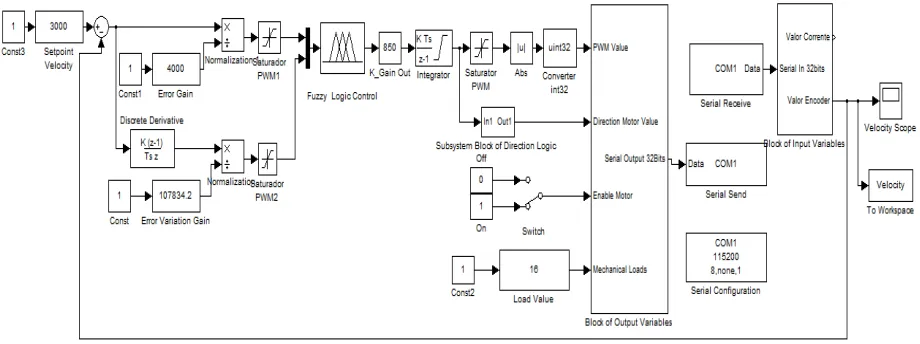
Figure 11 shows the MATLAB/Simulink block diagram suggested to the Fuzzy controller with the DC motor control kit.
Figure 11 – Block diagram of the Fuzzy controller.
VII. CONCLUSION
For the experiments performed, the gains of the PID controller were defined in a heuristic way by observing the dynamic response of the system, being its results satisfactory when subjected to setpoint and load variations. The FLC design proposed in this project, as an alternative technique,demonstrated that it is possible to use the Hardware/Software interface to implement other types of controllers, since their inputs and outputs must be the same ones supported by the interface.
application of digital control system for a DC motor.An improvement that can be made in MATLAB/Simulink serial communication is the use of the Packet Input and Output blocks, from Real-Time Windows Target library, where a sample frequency of 500 Hz could be achieved.
REFERENCES
[1] R.C. Dorf, R.H.Bishop, “Modern Control Systems”. Menlo Park, USA:Pearson,2001.
[2] A. E. Fitzgerald, C. Kingsley, S. D. Umans, “Electric Machinery,” 6 ed, New York: McGraw-Hill, 2003.
[3] E. J. Patané, “Implementation of closed loop speed control for DC motors using data acquisition system”. Master Thesis - Mauá Engineering School of the University Center of the Mauá Institute of Technology, São Caetano do Sul, São Paulo, 2008, pp. 123.
[4] Microchip, “dsPIC30F2010 datasheet”, 2004.
[5] ST Microelectronics, “L298–Dual Full-Bridge Driver–Datasheet”, 2000.
[6] K. J. Åström, T. Hägglund, “Advanced pid control,” Research TrianglePark (USA): International Society of Automation, 2006. [7] W. L. Torres, I. B. Q. Araujo, J. B. M. Filho, A. G. C. Junior, “Mathematical modeling and pid controller parameter tuning in a didactic
thermal plant,” IEEE Latin America Transactions, vol. 15, no. 7, pp. 1250-1256, 2017. [8] S.Bennett, G. S.Virk, “Computer control of real-time processes”. London, UK:IET, 1991.
[9] F. Cheong, R. Lai, “On simplifying the automatic design of a fuzzy logic controller,” Annual Meeting of the North American Fuzzy Information Processing Society Proceedings, 2002, pp. 481-487.