Improved Active Power Filter Performance
for Renewable Power Generation Systems by
Using Fuzzy Logic Controller
S. Naga Purnima1, N. Dharani Kumar2
PG Student, Dept. of EEE, RVR&JC College of Engineering, Chowdavaram, Guntur, AP, India1
Assistant Professor, Dept. of EEE, RVR&JC College of Engineering, Chowdavaram, Guntur, AP, India2
ABSTRACT
:
In this paper active power filter implementation with four leg VSC using a fuzzy logic controller scheme is presented. By using the four leg voltage source converter allows the compensation of current harmonic components as well as unbalanced current generated by non liner loads . the compensation performance of the proposed active power filter and transient operating conditions. In recent times fuzzy logic controller was applied for active power filter controller applications. In this paper A Fuzzy logic based shunt active power filter is presented and verified in Matlab simulation software.KEYWORDS: Active power filter, current controller, four leg converters, fuzzy logic controller.
I. INTRODUCTION
Renewable generation affects power quality due to its nonlinearity, since solar generation plants and wind power generators must be connected to the grid through high-power static PWM converters [2]. The non uniform nature of power generation directly affects voltage regulation and creates voltage distortion in power systems. This new scenario in power distribution systems will require more sophisticated compensation techniques. Although active power filters implemented with three-phase four-leg voltage-source inverters (4L-VSI) have already been presented in the technical literature [3]– [7], the primary contribution of this paper is a predictive control algorithm designed and implemented specifically for this application. Traditionally, active power filters have been controlled using fuzzy logic controller.
An accurate model obtained using fuzzy logic controllers improves the performance of the active power filter, especially during transient operating conditions, because it can quickly follow the current-reference signal while maintaining a constant dc-voltage. So far, implementations of fuzzy logic control in power converters have been used mainly in induction motor drives[10]–[17].In the case of motor drive applications, fuzzy logic control represents a very intuitive control scheme that handles multivariable characteristics, simplifies the treatment of dead-time compensations, and permits pulse-width modulator replacement. However, these kinds of applications present disadvantages related to oscillations and instability created from unknown load parameters [16]. One advantage of the proposed algorithm is that it fits well in active power filter applications, since the power converter output parameters are well known [18].
These output parameters are obtained from the converter output ripple filter and the power system equivalent impedance. The converter output ripple filter is part of the active power filter design and the power system impedance is obtained from well-known standard procedures [19], [20].In the case of unknown system impedance parameters, an estimation method can be used to derive an accurate R–L equivalent impedance model of the system [21].
II. FOUR-LEG CONVERTER MODEL
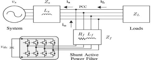
The below Fig. 1 shows the configuration of a typical power distribution system with renewable power generation. It consists of various types of power generation units and different types of loads. Renewable sources, such as wind and sunlight, are typically used to generate electricity for residential users and small industries. Both types of power generation use ac/ac and dc/ac static PWM converters for voltage conversion and battery banks for long term energy storage. These converters perform maximum power point tracking to extract the maximum energy possible from wind and sun. The electrical energy consumption behavior is random and unpredictable, and therefore, it may be single- or three-phase, balanced or unbalanced, and linear or nonlinear. An active power filter is connected in parallel at the point of common coupling to compensate current harmonics, current unbalance, and reactive power. It is composed by an electrolytic capacitor, a four-leg PWM converter, and a first order output ripple filter, as shown in Fig. 2. This circuit considers the power system equivalent impedance Zs , the converter output ripple filter impedance Zf , and the load impedance ZL .
Fig 1. Stand-alone hybrid power generation system with a shunt active power filter.
The four-leg PWM converter topology is shown in Fig. 3. This converter topology is similar to the conventional three-phase converter with the fourth leg connected to the neutral bus of the system. The fourth leg increases switching states from 8 (23) to 16 (24 ),improving control flexibility and output voltage quality [21], and is suitable for current unbalanced compensation.
Fig 2 Three-phase equivalent circuit of the proposed shunt active power filter.
Fig 3 Two-level four-leg PWM-VSI topology
The mathematical model of the filter derived from the equivalent circuit shown in Fig. 2 is
Where Req and Leq are the 4L-VSI output parameters expressed as Thevenin impedances at the converter output terminals Zeq. Therefore, the Thevenin equivalent impedance is determined by a series connection of the ripple filter impedance Zf and a parallel arrangement between the system equivalent impedance Zs and the load impedance
ZL
For this model, it is assumed that ZL>>Zs, that the resistive part of the system’s equivalent impedance is neglected, and
that the series reactance is in the range of 3–7% p.u., which is an acceptable approximation of the real system. Finally, in (2) Req =Rf and Leq =Ls+Lf.
III. DIGITALPREDICTIVECURRENTCONTROL
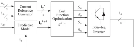
The block diagram of the proposed digital predictive current control scheme is shown in Fig. 3.4. This control scheme is basically an optimization algorithm and, therefore, it has to be implemented in a microprocessor. Consequently, the analysis has to be developed using discrete mathematics in order to consider additional restrictions such as time delays and approximations
Fig. 4. Proposed predictive digital current control block diagram
[10], [22]–[27]. The main characteristic of predictive control is the use of the system model to predict the future behaviour of the variables to be controlled. The controller uses this information to select the optimum switching state that will be applied to the power converter, according to predefined optimization criteria. The predictive control algorithm is easy to implement and to understand, and it can be implemented with three main blocks, as shown in Fig. 4.
A. Current Reference Generator:
This unit is designed to generate the required current reference that is used to compensate the undesirable load current components. In this case, the system voltages, the load currents, and the dc-voltage converter are measured, while the neutral output current and neutral load current are generated directly from these signals (IV).
B. Prediction Model:
The 16 possible output current predicted values can be obtained from (2) and (4) as
As shown in (5), in order to predict the output current io at the instant (k+1), the input voltage value vo and the
converter output voltage vxn, are required. The algorithm calculates all 16 values associated with the possible
combinations that the state variables can achieve.
C. Cost Function Optimization:
In order to select the optimal switching state that must be applied to the power converter, the16 predicted values obtained for io[k+1]are compared with the reference using a cost function, as follows:
The output current (io) is equal to the reference (i∗o) when g=0. Therefore, the optimization goal of the cost function is to
achieve a g value close to zero. The voltage vector vxN that minimizes the cost function is chosen and then applied at the next
sampling state. During each sampling state, the switching state that generates the minimum value of g is selected from the16 possible function values. The algorithm selects the switching state that produces this minimal value and applies it to the converter during thek+1state.
D. Current Reference Generation
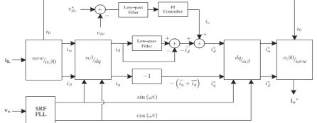
A dq-based current reference generator scheme is used to obtain the active power filter current reference signals. This scheme presents a fast and accurate signal tracking capability. This characteristic avoids voltage fluctuations that deteriorate the current reference signal affecting compensation performance [28]. The current reference signals are obtained from the corresponding load currents as shown in Fig. 3.5. This module calculates the reference signal currents required by the converter to compensate reactive power, current harmonic and current imbalance. The displacement power factor (sinφ (L)) and the maximum total harmonic distortion of the load (THD (L)) defines the relationships between the apparent power required by the active power filter, with respect to the load, as shown
Where the value of THD (L) includes the maximum compensable harmonic current, defined as double the sampling frequency fs.
The frequency of the maximum current harmonic component that can be compensated is equal to one half of the converter switching frequency. The dq-based scheme operates in a rotating reference frame. Therefore, the measured currents must be multiplied by the sin(wt) and cos(wt) signals. By using dq-transformation, the dcurrent component is synchronized with the corresponding phase-to-neutral system voltage, and the qcurrent component is phase-shifted by 90◦. The sin(wt) and cos(wt) synchronized reference signals are obtained from a synchronous reference frame (SRF) PLL [29]. The SRF-PLL generates a pure sinusoidal waveform even when the system voltage is severely
Distorted. Tracking errors are eliminated, since SRF-PLLs are designed to avoid phase voltage unbalancing, harmonics (i.e.,less than 5% and 3% in fifth and seventh, respectively), and offset caused by the nonlinear load conditions and measurement errors [30]. Equation (8) shows the relationship between the real currents iLx(t)(x=u, v, w) and the associated dq components(id and iq)
A low-pass filter (LFP) extracts the dc component of the phase currents id to generate the harmonic reference components− id. The reactive reference components of the phase-currents are obtained by phase-shifting the
corresponding ac and dc components of iq by 180◦. In order to keep the dc-voltage constant, the amplitude of the
converter reference current must be modified by adding an active power reference signal ie with the d-component, as will be explained in Section IV-A. The resulting signals i∗
d and i∗q are transformed back to a three-phasesystem by
applying the inverse Park and Clark transformation,as shown in (9). The cutoff frequency of the LPF used in thispaper is 20 Hz
The current that flows through the neutral of the load is compensated by injecting the same instantaneous value obtained From the phase-currents, phase-shifted by 180◦, as shown next
One of the major advantages of the dq-based current reference generator scheme is that it allows the implementation of a linear controller in the dc-voltage control loop. However, one important disadvantage of the dq-based current reference frame algorithm used to generate the current reference is that a second order harmonic component is generated in id and iq under unbalanced operating conditions. The amplitude of this harmonic depends on the percent of unbalanced load current (expressed as the relationship between the negative sequence current iL2andthe
positive sequence current iL1). The second-order harmonic cannot be removed from id and iq, and therefore generates
3.athird harmonic in the reference current when it is converted back to abc frame [31]. Fig. 3.6 shows the percent of system current imbalance and the percent of third harmonic system current, in function of the percent of load current imbalance. Since the load current does not have a third harmonic, the one generated by the active power filter flows to the power system.
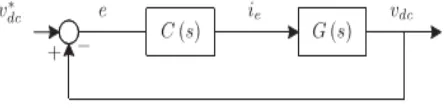
Fig. 6. DC-voltage control block diagram.
IV. DC-VOLTAGE CONTROL
operating conditions are required. Additionally, the slow dynamic response of the voltage across the electrolytic capacitor does not affect the current transient response. For this reason, the PI controller represents a simple and effective alternative for the dc-voltage control. The dc-voltage remains constant (with a minimum value of √6vs(RMS))
until the active power absorbed by the converter decreases to a level where it is unable to compensate for its losses. The active power absorbed by the converter is controlled by adjusting the amplitude of the active power reference signal ie, which is in phase with each phase voltage. In the block diagram shown in Fig. 3.5, the dc-voltage vdc is measured and
then compared with a constant reference value v∗
dc. The error(e) is processed by a PI controller, with two gains, Kp and
Ti. Both gains are calculated according to the dynamic response requirement. Fig. 6 shows that the output of the PI controller is fed to the dc-voltage transfer function Gs, which is represented by a first-order
The equivalent closed-loop transfer function of the given system with a PI controller (12) is shown in (13)
Since the time response of the dc-voltage control loop does not need to be fast, a damping factor ζ=1and a natural
angular speed ωn=2π·100 rad/s are used to obtain a critically damped response with minimal voltage oscillation. The
corresponding integral time Ti =1/a(13) and proportional gain Kp can be calculated as
V. FUZZY LOGIC CONTROLLER
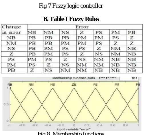
In FLC, basic control action is determined by a set of linguistic rules. These rules are determined by the system. Since the numerical variables are converted into linguistic variables, mathematical modeling of the system is not required in FC. The FLC comprises of three parts: Fuzzification , interference engine and defuzzification. The FC is characterized as
i. seven fuzzy sets for each input and output ,ii. Triangular membership functions for simplicity, iii. Fuzzification using continuous universe of discourse, iv. Implication using Mamdani’s, ‘min’ operator. v. Defuzzification using the height method.
A. Fuzzification: Membership function values are assigned to the linguistic variables, using seven fuzzy subsets: NB (Negative Big), NM (Negative Medium), NS (Negative Small), ZE (Zero), PS (Positive Small),
Fig 7 Fuzzy logic controller
B. Table I Fuzzy Rules
Fig 8 Membership functions
B. Inference Method: Several composition methods such as Max–Min and Max-Dot have been proposed in the literature. In this paper Min method is used. The output membership function of each rule is given by the minimum operator and maximum operator. Table 1 shows rule base of the FLC.
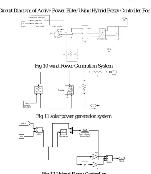
VI. SIMULATED RESULTS
Fig9 Circuit Diagram of Active Power Filter Using Hybrid Fuzzy Controller For RES
Fig 10 wind Power Generation System
Fig 11 solar power generation system
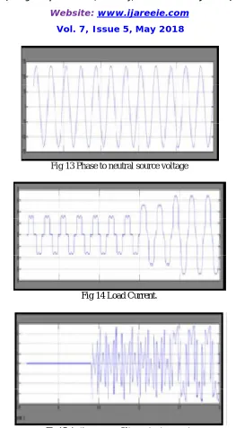
Fig 13 Phase to neutral source voltage
Fig 14 Load Current.
Fig15 Active power filter output current.
Fig 17 System neutral current.
Fig 18 System currents.
Fig 19 DC voltage converter.
Fig 20 Non linear load current
VII. CONCLUSION
In this paper, The use of fuzzy logic controller proved to be an effective solution for active power filter applications. It will improves the currenttracking capability, Dynamic performance andtransient response. Simulated results have proved thatthe proposed fuzzy control method is good alternativeto renewable power generation systems. An improvedfuzzy logic based shunt APF is proposed, which issuitable for digital control realization.
REFERENCES
[1] Pablo Acuna,Luis Moran,Marco Rivera,Juan Dixon, and Jos Rodriguez, “Improved active power filter performance for renewable powe generation systems,” IEEE Trans. Power Electron., vol. 29, no. 2, pp. 0885-8993, Feb. 2014.
[2] J. Rocabert, A. Luna, F. Blaabjerg, and P. Rodriguez, “Control of power converters in AC microgrids,” IEEE Trans. Power Electron., vol. 27, no. 11, pp. 4734–4749, Nov. 2012.
[3] M. Aredes, J. Hafner, and K. Heumann, “Threephase four-wire shunt active filter control strategies,” IEEE Trans. Power Electron., vol. 12, no. 2, pp. 311– 318, Mar. 1997.
[4] S. Naidu and D. Fernandes, “Dynamic voltage restorer based on a fourleg voltage source converter,” Gener. Transm. Distrib., IET, vol. 3, no. 5, pp. 437–447, May 2009.
[5] N. Prabhakar and M. Mishra, “Dynamic hysteresis current control to minimize switching for three-phase four-leg VSI topology to compensate nonlinear load,” IEEE Trans. Power Electron., vol. 25, no. 8, pp. 1935–1942, Aug. 2010.
[6] V. Khadkikar, A. Chandra, and B. Singh, “Digital signal processor implementation and performance evaluation of split capacitor, four-leg and three h-bridge-based three-phase four-wire shunt active filters,” Power Electron., IET, vol. 4, no. 4, pp. 463–470, Apr. 2011.
[7] F. Wang, J. Duarte, and M. Hendrix, “Gridinterfacing converter systems with enhanced voltage quality for micro grid application; concept and implementation,” IEEE Trans. Power Electron., vol. 26, no. 12, pp. 3501– 3513, Dec. 2011
[8] X. Wei, “Study on digital pi control of current loop in active power filter,”in Proc. 2010 Int. Conf. Electr. Control Eng., Jun. 2010, pp. 4287–4290.
[9] R. de Araujo Ribeiro, C. de Azevedo, and R. de Sousa, “A robust adaptive control strategy of active
power filters for power-factor correction, harmonic compensation, and balancing of nonlinear loads,” IEEE Trans. Power Electron., vol. 27, no. 2, pp. 718–730, Feb. 2012.