A Novel Multi Objective under Frequency
Load Shedding in a Micro-Grid using Genetic
Algorithm
Mallarapu Pushpanjali
1,
Dr. M.S.Sujatha
2PG Student [EPS], Dept. of EEE, Sree Vidyanikethan Engineering College, Tirupati, Andhra Pradesh, India1.
Professor, Dept. of EEE, Sree Vidyanikethan Engineering College, Tirupati, Andhra Pradesh, India2.
ABSTRACT:Load shedding is an important approach to maintain the power system in a stable and reliable condition when they suffer from severe disturbance. The under frequency load shedding is one of the load shedding facilities, provides protection to the system when the system frequency declines to pre-specified settings. The paper presents the application of genetic algorithm for an under frequency load shedding for a micro-grid towards an accidental over load condition which require load shedding action. For a micro-grid, over load can occur due to various reasons ranging from outage of one or more generators inside the micro-grid, poor load schedule, illegal load connections by some low voltage customers, inadequate switching circuits, etc. Genetic Algorithm (GA) is applied to determine the amount of load to be shed to maintain the frequency within the limits.
KEYWORDS: Load shedding, Genetic Algorithm, Micro-Grid, Tree encoding, Distributed Generator.
I. INTRODUCTION
Electrical power system under steady state conditions, involves a balanced exchange of power between generation and various loads for stable operation [1]. Imbalances in generation and load demand leads to deviation of frequency from nominal value. If generation increases more than load demand, system frequency increases and if generation is less than load demand, system frequency drops from nominal value. When a large power source is lost the frequency drops rapidly. To avoid this deviation, particularly severe frequency drop is very important because the blades of steam turbines become heavily stressed due to natural frequencies resulting in higher oscillations [2]. These abnormal conditions can lead to thermal over load of generator, and there is a strong possibility for a generating unit trip due to protection activation. This may lead to cascaded generator trips and a black-out. Under frequency condition in a stand-alone power system (e.g., micro-grid) occurs due to loss of a major Distributed Generator (DG). Electric power utilities adopt different protection schemes to solve this problem, under frequency load shedding (UFLS) is one of the method.
UFLS is a very important approach to prevent frequency decline. It should have capability not only to shed load under different operating modes when local systems are connected to the main systems, but also capable to maintain the frequency stability when local systems are islanded. The frequency decline is considered as a serious problem, caused by the power imbalance between generation and demand which lead to the excess load. UFLS schemes are a last resort tool to protect the power system in case of a severe disturbance [3]. In small isolated power systems, UFLS schemes play an important role in protecting the system integrity.
by determination of the magnitude of the disturbance. Different load-shedding schemes were developed by T. Tomsic et.al in [8] a fixed maximal load for shedding and shed loads proportional to the frequency gradient. L. Sigrist et.al [9] proposed a method to design 81L UFLS for selecting representative operating and contingency scenarios.
Most of the UFLS schemes implemented today are conventional static and semi-adaptive schemes [10]. The primary method to bring back to the nominal frequency level is to shed amount of load. In power systems protection, the frequencies are widely used as a setting in UFLS design. UFLS must be performed quickly to arrest power system frequency decline by decreasing power system load to match available generating capacity. Extreme frequency decline can occur within seconds. There are many methods for under frequency load shedding. These methods have some drawbacks like one stage shedding, and load shedding than required, slow response time. To overcome these drawbacks Genetic Algorithm (GA) is applied to determine the amount of load to be shed to maintain frequency nearer to nominal value.
II. UNDER FREQUENCY LOAD SHEDDING
When there is a loss of generation or sudden increase of load causes imbalances in power system resulting in a severe frequency decline, emergency action such as under frequency load shedding may be needed. Even for a short interval of time, if system frequency reaches a given threshold, power stations may trip off resulting in further load imbalance which may lead to a global system collapse.
Load shedding is an effective corrective control action in which a part of the system loads are is connected according to certain priority in order to steer the power system from the existing potential dangers with the least probability of disconnecting the importance loads. Load shedding is considered as the last resort tool for use in that extreme situation and usually the less preferred action to be adopted, but in this kind of problem it is vital to prevent the system from collapsing.
When there is a major disturbance, the power system DGs may enter the emergency state. Load shedding is one of the emergency control actions. It is needed in the following conditions as given: When there is a disturbance in the grid system, when there is a major disturbance in distributing generation system itself or when there is a major disturbance in the interconnection, the power systems with distributed generation may be disconnected from the grid system.
III. EXISTING METHODS
This section gives a brief description about the existing load shedding techniques having their own applications and drawbacks [5].
A. Breaker Interlock Load Shedding: In this method of load shedding the circuit breaker interdependencies are arranged to operate based on hardwired trip signals from a circuit breaker or a generator trip. This method is often used when the speed of the load shedding is critical. It is very simple method of load shedding and the execution time of this scheme is fast.
Drawbacks: • Load shedding based on worst-case scenario. • Only one stage of load shedding. • More than required load is shed. • Modifications to the system are costly.
B. Under-Frequency Relay Load Shedding: For setting up of a frequency load shedding stages are common for both large and small systems for this method. Fixed load reduction at fixed system frequency levels are considered for the design methodology. The frequency relay trips one or more load breakers upon reaching the frequency set point and expiration of pre-specified time delay. This method of load shedding can be totally independent of the system dynamics, total loss of the system is an assumed possibility.
Drawbacks: • Response time is slow. • Incorrect / excessive load shedding. • Analysis knowledge is always lost.
C. Programmable Logic Controller: Load shedding is initiated based on the total load versus the number of generators online and/or detection of under-frequency conditions. Each substation PLC is programmed to initiate a trip signal to the appropriate feeder breakers to shed a preset sequence of loads. This static sequence is continued until the frequency returns to a normal, stable level.
To overcome the drawbacks of excessive, incorrect and fixed amount of load shedding stages GA is applied to calculate the appropriate amount of load to be shed to maintain the frequency at the required frequency.
IV. DIFFERENCES BETWEEN LARGE POWER SYSTEM AND A MICRO-GRID FOR LOAD SHEDDING
UFLS scheme in micro-grid different from large power system as explained below:
1. In large power systems, engineers may consider forced and scheduled outages in setting the parameters of under frequency relays. In micro-grids, only forced outage is considered because the voltage is low and most of the loads are insensitive [5].
2. The total number of shedding stages is large (e.g., 12), and for a micro-grid the total number of load-shedding stages is small (e.g., 4~6).
3. The maximal shed load, which must be defined for large power systems, is usually 30% of the system peak load. The shed load at each stage is the maximal shed load divided by the number of stages. However, in a micro-grid, the shed load at the first stage is expected to be the largest among all stages and the shed loads at the subsequent stages decrease gradually to increase the efficiency of the UFLS scheme.
4. Generations from most of generating units are assumed to be according to the load profile in large power systems. A scenario with the largest peak load is considered to be a base case for determining the parameters of under frequency relays. In addition, the load patterns in other scenarios are assumed to be proportional to those in the base case. Therefore, the shed loads in other scenarios are only fractions of those obtained in the scenario with the largest peak load. However, this assumption is inapplicable in the micro-grid, because of the intermittent and meteorological data-dependent nature of renewable energies.
5. The inertias of the generating units are large in a power system, while those of the power inverter-based renewable impact the frequency in the micro-grid to a lesser extent.
The following are the factors that are considered while designing the parameters of an under frequency relay [2]:
1. Maximum amount of load for load shedding. 2. Parameters of under frequency relay. 3. Shed amount at each stage.
The following are the assumptions considered for the proposed work:
1. When a large disturbance occurring in the main power system, and if the micro-grid is connected to the main power system, the disturbance in main power system does not impacts the micro-grid, a static switch located at the point of common coupling disconnects the micro-grid from the main power grid and no load shedding is required in the micro-grid.
2. If the micro-grid is connected to the main power system and a disturbance occurs in the micro-grid, the frequency in the micro-grid remains stable and no load shedding in the micro-grid is required.
3. If the micro-grid is islanding and loss of the main generation source causes the frequency to decrease, UFLS relays serve the only special protection scheme in the micro-grid.
4. The utility owns the main grid but not the micro-grid. Parameters of the UFLS relay determined by the decision maker in the micro-grid do not need to coordinate with those in the main grid.
V. PROBLEM FORMULATION FOR MICRO-GRID LOAD SHEDDING
A decision maker in a micro-grid seeks to minimize the load shed and to maximize the lowest swing frequency. The problem can be formulated as follows,
Min f1(L1,L2,...,Ls) (1)
S
min≤ S ≤ S
max (3)(4)
L1≥L2 ≥L3 ≥... ≥Ls (5)
along with the system dynamic equations. The terms f1andf2 represent the total shed load and the lowest swing
frequency that is caused by a disturbance, respectively. Equations (1)–(5) and the system dynamic equations constitute a multi objective nonlinear problem. Minimizing the negative lowest swing frequency in (2) is equivalent to maximizing the lowest swing frequency. Smax and Smin represent the maximum and minimum number of stages, respectively. Furthermore, L1, L2 ...Lt ...Lsare the shed loads for stages1, 2 ...t ...S, where S denotes the number of
stages. Lmin and Lmax represent the maximum and minimum amounts of shed loads, respectively.
VI. PROPOSED METHOD
Genetic Algorithms (GAs) are adaptive methods which may be used to solve search and optimization problems. They are based on the genetic processes of biological organisms. Over many generations, natural populations evolve according to the principles of natural selection and survival of the fittest. It is first clearly stated by Charles Darwin in the Origin of Species. By mimicking this process, genetic algorithms are able to evolve solutions to real world problems, if they have been suitably encoded [11]-[12].
The GA is applied for the UFLS problem for three reasons: 1) The GA can approach global optimum.
2) The GA can deal with inequality constraints efficiently. 3) The GA does not need to calculate the derivatives of f1and f2.
The following are the steps used for implementing GA to get the optimal solution for UFLS.
A. Tree-encoding chromosome
In order to ensure L1≥L2 ≥L3 ≥………. ≥Ls, tree encoding chromosome is used in this work. Each individual
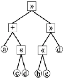
chromosome consists of genes. The tree-encoding based chromosome includes: 1) Operands: real numbers a, b, c ... and
2) Operators +, <<, and >>.
The operation for (a<<b) is defined here as 0.5a+b while the operation for (a>>b) is a+0.5b. Figure 1 shows an example of tree-encoding chromosome.
Figure 1: Example of tree-encoding chromosome.
The values of 3rd, 2nd and 1st levels are defined as a+(c<<d)+(b<<e)+d, (a+(c<<d)+(b<<e)>>d), and (a+(c<<d)>>(b<<e)>>d), respectively. Based on the tree-encoding chromosome, the shed load Lt at stage t, t=1, 2... S is
defined as the value of the t th level divided by 2t-1 as represented in below equations (6)-(8).
m ax
1 m in
L
L
L
s
t
t
4
]
)
5
.
0
(
)
5
.
0
(
[
3d
e
b
d
c
a
L
(6)2
]}
5
.
0
)
5
.
0
(
)
5
.
0
(
{[
2d
e
b
d
c
a
L
(7)]
5
.
0
)
5
.
0
[(
5
.
0
)]
5
.
0
(
[
1
a
c
d
b
e
d
L
(8)B. Crossover and Mutation Operations
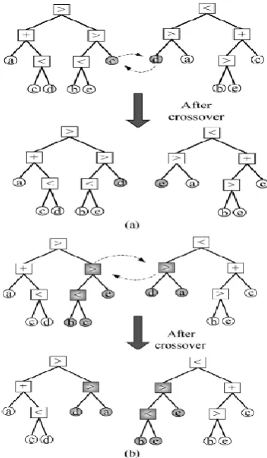
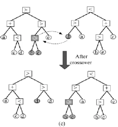
In GA, fitness function is defined and the optimal solution is obtained by repeating crossover and mutation operations. Crossover operation: One of the methods of generating new chromosomes is the crossover operation. The operation randomly chooses two chromosomes as parents and exchanges parts of them, as shown in Figure 2. The crossover operation between two chromosomes with the crossover between two operands is as shown in Figure 2(a), between two operators is as shown in Figure 2(b) and between an operand and an operator is shown in Figure 2(c).
Mutation operation: A particular bit is stochastically chosen and its value is flipped to generate a new chromosome.
Figure 2: (c) Crossover operation between an operand and an operator.
C. Evaluation
In order to identify the candidates that may survive to the next generation, each chromosome is evaluated according to the fitness function and assigned a fitness value. The fitness function is defined according to the required solution.
D. Selection
New chromosomes are generated by executing the crossover and mutation operations, which may have higher fitness values. The number of chromosomes in a population is fixed during a search, it is necessary to select from among the old and new chromosomes. While there are various policies concerning selection, the typical operation is the roulette wheel selection. This is a method is called fitness-proportionate selection in which selection is made with probability proportional to the fitness value [6]. With the roulette selection, chromosomes with higher fitness values are likely to survive as members of the next generation. Once selection is completed, a new population is ready for the next generation.
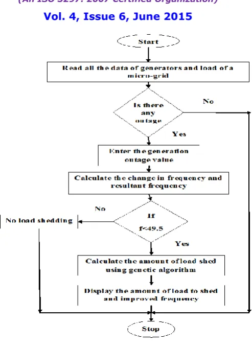
E. Flowchart of proposed algorithm
Figure 3: Flowchart of the proposed method. VII. TEST SYSTEM AND RESULTS
Consider a micro-grid test system with 5 DGs feeding a constant load. The generation capacities of these distributed generators are 10kW, 31.5kW, 60kW, 25kW, 5kW with a total constant load of 131.5 kW. Frequency of the system is 50Hz. Figure 4 illustrates the single line diagram of the considered micro grid.
In this micro-grid, the first stage frequency for the UFLS relay is set to 49.5Hz. The minimum and maximum shed loads (Lmin and Lmax) were set to be 0kW and 30% of total system load (131.5kW) (i.e., 39.45 kW respectively). Smin and Smax in equation (3) were set to be 0 and 6, respectively.
The paper considers N-1 outages, which represents to a single component outage of the system. The change in frequency is calculated through the system swing equation. If the frequency limits are violated the amount of load to be shed can be calculated by applying GA.
The parameters of GA for this problem are taken respectively as follows: Population size as 20, elite count as 1, single point cross over with cross over rate of 0.8, mutation function as mutationadaptfeasible, with roulette wheel selection and total number of generations of 200.
With the DG1 outage the frequency is within the limits so, no load shedding action is required. With the outage of
DG3 the change in frequency is 1.1407 and the resultant frequency is 48.859 Hz which is less than 49.5Hz so, load
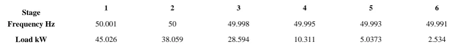
shedding action is required in order to protect the system from blackouts. The amount of load to be shed at with different frequency ranges is calculated using GA. The frequency and load values obtained by applying GA for an outage of DG3 are given in Table I.
Table I: Frequency and load shedding values for an outage of DG3
Stage 1 2 3 4 5 6
Frequency Hz 50.001 50 49.998 49.995 49.993 49.991
Load kW 45.026 38.059 28.594 10.311 5.0373 2.534
From the above results of DG3 outage, stage 2 can be activated for load shedding to increase the system frequency to
50Hz.
By implementing GA to calculate the amount of load shed, it reduces unnecessary amount of load disconnecting from the supply. Table II represents the comparison between the conventional load shedding method and the proposed genetic algorithm method for all the outages of DG with single outages.
Table II:Comparison between Conventional Method and Genetic Algorithm Approach
Outage DG Actual outage value in kW
Change in frequency
df/dt
Frequency Hz Amount of load shed kW
Conventional method Genetic Algorithm
1 10 0.19011 49.81 No load shedding No load shedding 2 31.5 0.59886 49.401 22.986 20.526 3 60 1.1407 48.859 43.76 38.59 4 25 0.47529 49.525 No load shedding No load shedding 5 5 0.55916 49.441 No load shedding No load shedding
VIII. CASE STUDY
Table III: Import details of Renigunta 220/132 kV Sub-Station Manubolu-1 55 MW
Manubolu-2 55 MW CK Palli 135 MW
Kodur 70 MW Total 315 MW
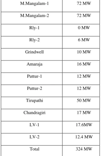
Table III represents the import details of Renigunta power system substation and the Table IV represents the export details of Renigunta power system substation.
Table IV:Export details of Renigunta 220/132 kV sub-station M.Mangalam-1 72 MW M.Mangalam-2 72 MW Rly-1 0 MW Rly-2 6 MW Grindwell 10 MW
Amaraja 16 MW Puttur-1 12 MW Puttur-2 12 MW Tirupathi 50 MW Chandragiri 17 MW LV-1 17.6MW LV-2 12.4 MW Total 324 MW
Assuming that there is an outage of 135MW input power, the change in frequency is df/dt = -1.0714Hz, the resultant frequency is f = 48.929 Hz. The load shedding stages obtained by the proposed methodology are represented in Table V.
Table V:Load shedding stages for an outage of 135MW of input power
Stage 1 2 3 4 5 6
Frequency
Hz 50.002 50 49.995 49.988 49.98 49.972 Load MW 100.07 91.13 80.111 70.438 60.781 50.029
IX. CONCLUSION
Load shedding is required to maintain the balance between generation and load. There are several methods used for under frequency load shedding. To overcome the drawbacks of existing methods of under frequency load shedding GA is applied to calculate the amount of load to be shed.
A new load shedding method is developed by means of GA to determine the optimal amount of load to be shed so that power system can remain in a secure condition. The results obtained are compared with the conventional method. The method has proven to be a more effective in determining the optimal value of load shed. The same methodology is applied to Renigunta substation.
REFERENCES
[1] Ying-Yi Hong, Ming-Chun Hsiao, Yung-Ruei Chang, Yih-Der Lee, and Hui-Chun Huang "Multi scenario Under Frequency Load Shedding in a Micro-grid Consisting of Intermittent Renewables," IEEE Transactions on power delivery, Vol.28, No.3, July 2013.
[2] Y. Y. Hong and S. F. Wei, “Multi-objective under frequency load shedding in an autonomous system using hierarchical genetic algorithms,”
IEEE Trans. Power Del., vol. 25, no. 3, pp. 1355–1362, Jul. 2010.
[3] L. Sigrist, I. Egido, and L. Rouco, “A method for the design of UFLS schemes of small isolated power systems,” IEEE Trans. Power Syst., vol. 27, no. 2, pp. 951–958, May 2012.
[4] Y. Y. Hong and S. F. Wei, “Multi-objective under frequency load shedding in an autonomous system using hierarchical genetic algorithms,”
IEEE Trans. Power Del., vol. 25, no. 3, pp. 1355–1362, Jul. 2010.
[5] Y. Y. Hong and P. H. Chen, “Genetic-based under-frequency load shedding in a standalone power system considering fuzzy loads,” IEEE Trans. Power Del., vol. 27, no. 1, pp. 87–95, Jan. 2012.
[6] E. J. Thalassinakis and E. N. Dialynas, “A Monte-Carlo simulation method for setting the under frequency load shedding relays and selecting the spinning reserve policy in autonomous power systems,” IEEE Trans. Power Syst., vol. 19, no. 4, pp. 2044–2052, Nov. 2004.
[7] V. Vladimir and V. Terzija, “Adaptive under frequency load shedding based on the magnitude of the disturbance estimation,” IEEE Trans. Power Syst., vol. 21, no. 3, pp. 1260–1266, Aug. 2006.
[8] T. Tomsic, G. Verbi c, and F. Gubina, “Revision of the under frequency load-shedding scheme of the Slovenian power system,” Elect. Power Syst. Res., vol. 77, pp. 494–500, 2007.
[9] L. Sigrist, I. Egido, and L. Rouco, “A method for the design of UFLS schemes of small isolated power systems,” IEEE Trans. Power Syst., vol. 27, no. 2, pp. 951–958, May 2012.
[10] Tanujkhandewal, Shervinshokooh, "Intellegent Load Shedding Need for a Fast and Optimal Solution," IEEE PCIC, Europe, 2005. [11] Franz Rothlauf, Representations for Genetic and Evolutionary Algorithms, Spinger, Netherlands, Second edition, 2006.
[12] Hitoshi Iba, Topon Kumar Paul, Yoshihiko Hasegawa, Applied Genetic Programming and Machine Learning, The CRC Press, United States of America, 2010.
BIOGRAPHY
1
Mallarapu Pushpanjali pursuing M.Tech. Electrical Power Systems in Sree Vidyanikethan Engineering College and received B.Tech degree from JNTU Anantapur University in Electrical and Electronic Engineering from Sri Sai Institute of Technology and Science, Rayachoty in 2013, respectively. Areas of interest are Power Systems, Electrical Machines, and Power System Protection.
2