c e-ISSN: 2348-6848, p- ISSN: 2348-795X Volume 3, Issue 01, January 2016
International Journal of Research (IJR)
Available at http://internationaljournalofresearch.org
Design & Simulation of Improved Active Power Filter for
Renewable Energy Power Applications
K.Siva
1& S. Raj shekar
2 1M.Tech Scholar, Dept of EEE, ASR College of Engineering and Technology, JNTUK, A.P
2Assistant Professor, Dept of EEE, ASR College of Engineering and Technology, JNTUK, A.P
Abstract: —
In this paper an active power filter implemented
with a four-leg voltage-source inverter using a
predictive control scheme is presented. The use
of a four-leg voltage source inverter allows the
compensation ofcurrentharmonic components, as
well as unbalanced current generated by
single-phase nonlinear loads. A detailed yet simple
mathematical model of the active power filter,
including the effect of the equivalent power
system impedance, is derived and used to design
the
predictive
control
algorithm.
The
compensation performance of the proposed
active power filter and the associated control
scheme under steady state and transient
operating conditions is demonstrated through
simulations results. In recent times, fuzzy logic
controller was applied for active power filter
(APF) control application, as the APF is nothing
but a current controlled VSI. In this project, a
fuzzy logic based shunt APF is presented based
on the effective time concept. The effective time
concept eliminates the trigonometric calculations
and sector identification, thereby it reduces the
computational
effort.
Simulation
results
demonstrate the efficacy of the APF with the
fuzzy logic based control strategy. Simulation
results are obtained for both predictive control
scheme and fuzzy logic controller and the results
are care compared. The response time for
compensation is 0.02sec. Computer simulation
by MATLAB/ SIMULINK has been used to
support the developed concept.
Keywords:
Active
power
filter;
current
control; four-leg converters; predictive control;
Fuzzy logic controller
I.
INTRODUCTION
c e-ISSN: 2348-6848, p- ISSN: 2348-795X Volume 3, Issue 01, January 2016
International Journal of Research (IJR)
Available at http://internationaljournalofresearch.org
operate in both standalone and grid-connected
modes flexibly according to Grid conditions [1],
[2]. When the utility grid is not available or the
utility power is accidentally lost, the DG is used
as an on-site power or standby emergency power
service,
effectively
being
an
extended
uninterruptible power supply (UPS) that is
capable of providing long-term energy supply.
The non-linear load current harmonics may
result in voltage harmonics and can create a
serious PQ problem in the power system
network. Active power filters (APF) are
extensively used to compensate the load current
harmonics and load unbalance at distribution
level. This results in an additional hardware cost.
However,
in
this
paper
authors
have
incorporated. The features of APF in the,
conventional inverter interfacing renewable with
the grid, without any additional hardware cost.
This paper presents the mathematical
model of the 4L-VSI and the principles of
operation of the proposed predictive control
scheme, including the design procedure. The
complete description of the selected current
reference generator implemented in the active
power filter is also presented. Finally, the
proposed
active
power
filter
and
the
effectiveness of the associated control scheme
compensation
are
demonstrated
through
simulation and validated with experimental
results
obtained
in
a
2
kVA
laboratory prototype.
II.
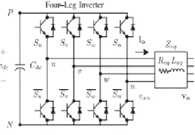
PROPOSED TOPOLOGY – FOUR LEG
CONVERTER MODEL
The four-leg PWM converter topology is
shown in Fig. 1. This converter topology is
similar to the conventional three-phase
converter with the fourth leg connected to the
neutral bus of the system. The fourth leg
increases switching states from 8 (23) to 16
(24), improving control flexibility and output
voltage quality [11], and is suitable for current
unbalanced compensation.
Fig. 1. Two-level four-leg PWM-VSI topology
III. PROPOSED TOPOLOGY –DIGITAL
PREDICTIVECURRENTCONTROL The block diagram of the proposed digital predictive current control scheme is shown in Fig. 2. This control scheme is basically an optimization algorithm and, therefore, it has to be implemented in a microprocessor. Consequently, the analysis has to be developed using discrete mathematics in order to consider additional restrictions such as time delays and approximations [10], [11–[12]. The main characteristic of predictive
control is
the use of the system model to predict the future behaviour of the variables to be controlled. The controller uses this information to select the optimum switching state that will be applied to the power converter, according to predefined optimization criteria. The predictive control algorithm is easy to implement and to understand, and it can be implemented with three main blocks, as shown in Fig. 2.
c e-ISSN: 2348-6848, p- ISSN: 2348-795X Volume 3, Issue 01, January 2016
International Journal of Research (IJR)
Available at http://internationaljournalofresearch.org
IV. PROPOSED TOPOLOGY –CURRENT REFERENCE
GENERATION
A dq-based current reference generator scheme is used to obtain the active power filter current reference
signals. This scheme
presents a fast and accurate signal tracking capability. This characteristic avoids voltage fluctuations that deteriorate the current reference signal affecting compensation performance [4]. The current reference signals are obtained from the corresponding load currents as shown in Fig. 3. This module calculates the reference signal currents required by the converter to compensate
reactive power, current harmonic and current imbalance. The displacement power factor (sin φ(L)) and the maximum total harmonic distortion of the load (THD(L)) defines the relationships between the apparent power required by the active power filter, with respect to the load, as shown
where the value of THD (L) includes the maximum compensable harmonic current, defined as double the sampling frequency fs. The frequency of the maximum
current harmonic component
that can be compensated is equal to one half of the converter switching frequency.
Fig.3.dq-based current reference generator block diagram. The dq-based scheme operates in a rotating reference frame; therefore, the measured currents must be multiplied by the sin(wt) and cos(wt) signals. By using dq -transformation, the d current component is synchronized with the corresponding phase-to-neutral system voltage, and the q current component is phase-shifted by 90◦. The sin(wt) and cos(wt) synchronized reference signals are
obtained from a synchronous reference frame (SRF) PLL [9]. The SRF-PLL generates a pure sinusoidal waveform even when the system voltage is severely distorted. Tracking errors are eliminated, since SRF-PLLs are designed to avoid phase voltage unbalancing, harmonics (i.e., less than 5% and 3% in fifth and seventh, respectively), and offset caused by the nonlinear load conditions and measurement errors [13]. The bellow equation shows the relationship between the real currents iLx(t) (x = u,v,w) and the associated dq components (id and iq )
A low-pass filter (LFP) extracts the dc component of the phase currents id to generate the harmonic reference components −id. The reactive reference components of the phase-currents are obtained by phase-shifting the corresponding ac and dc components of Iq by 180◦. In order to keep the dc-voltage constant, the amplitude of the converter reference current must be modified by adding an active power reference signal ie with the d -component. The resulting signals i∗ d and i∗ q are transformed back to a three-phase system by applying the inverse Park and Clark transformation, as shown in bellow equation. The cutoff frequency of the LPF used in this paper is 20 Hz
The current that flows through the neutral of the load is compensated by injecting the same instantaneous value obtained from the phase-currents, phase-shifted by 180◦, as shown next
One of the major advantages of the dq-based current reference generator scheme is that it allows the implementation of a linear controller in the dc voltage control loop. However, one important disadvantage of the
c e-ISSN: 2348-6848, p- ISSN: 2348-795X Volume 3, Issue 01, January 2016
International Journal of Research (IJR)
Available at http://internationaljournalofresearch.org
harmonic component is generated in id and iq under unbalanced operating conditions. The amplitude of this harmonic depends on the percent of unbalanced load current (expressed as the relationship between the negative sequence current iL,2 and the positive sequence current
iL,1). The second-order harmonic cannot be removed from
id and iq , and therefore generates a third harmonic in the reference current when it is converted back to abc frame [11]. Fig. 4. shows the percent of system current imbalance and the percent of third harmonic system current, in function of the percent of load current imbalance. Since the load current does not have a third harmonic, the one generated by the active power filter flows to the power system.
Fig. 4.Relationship between permissible unbalance load currents, the corresponding third-order harmonic content,
and system current imbalance (with respect to positive sequence of the system current, is,1 )
V. MATLAB BASED SIMULATION &RESULTS
DISCUSSION
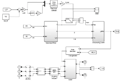
To verify the feasibility of the proposed system a simulink model is developed with modular converter which gives output. Fig.5 & Fig.6 shows the sub system in the developed simulink model
Fig.5. MATLAB based simulation diagram of proposed system with masked blocks
Fig.6. MATLAB based simulation diagram of proposed system with masked blocks
Fig.7. Shows the MATLAB based simulation of the proposed control scheme dc voltage
Fig.7. MATLAB based simulation of the proposed control scheme dc voltage
Fig.8. Shows the MATLAB based simulation of the proposed control scheme Load Current
Fig.8. MATLAB based simulation of the proposed control scheme Load Current
c e-ISSN: 2348-6848, p- ISSN: 2348-795X Volume 3, Issue 01, January 2016
International Journal of Research (IJR)
Available at http://internationaljournalofresearch.org
Fig.9. MATLAB based simulation of the proposed control scheme - Active power filter neautral current
Fig.10. Shows the MATLAB based simulation of the proposed control scheme – Isabc
Fig.10.MATLAB based simulation of the proposed control scheme - Isabc
The compensation effectiveness of the active power filter is corroborated in a 2 kVA experimental setup. A six-pulse rectifier was selected as a nonlinear load in order to verify the effectiveness of the current harmonic compensation. A step load change was applied to evaluate the transient response of the dc voltage loop. Finally, an unbalanced load was used to validate the performance of the neutral current compensation. Because the experimental implementation was performed on a dSPACE I/O board, all I/O Simulink blocks used in the simulations are 100% compatible with the dSPACE system capabilities. The complete control loop is executed by the controller every 20 μs, while the selected switching state is available at 16 μs. An average switching frequency of 4.64 kHz is obtained.
Table.I shows the simulation parameters for the proposed system
TABLE.I.SIMULATION SPECIFICATIONS
Parameter Rating
Source Voltage 55 V
Dc Voltage 162 V
Frequency 50Hz
DC Voltage 760
DC Link Capacitance 2200 µF
Sampling Time 20 µsec
4 kW
Filter Inductance 5 mH
CONCLUSION
Improved dynamic current harmonics and a reactive power compensation scheme for power distribution systems with generation from renewable sources has been proposed to improve the current quality of the distribution system. Advantages of the proposed scheme are related to its simplicity, modeling, and implementation. The use of a predictive control algorithm for the converter current loop proved to be an effective solution for active power filter applications, improving current tracking capability, and transient response. Simulated and experimental results have proved that the proposed predictive control algorithm is a good alternative to classical linear control methods. The predictive current control algorithm is a stable and robust solution. Simulated and experimental results have shown the compensation effectiveness of the proposed active power filter.
R
EFERENCES[1] J. Rocabert, A. Luna, F. Blaabjerg, and P. Rodriguez, “Control of power converters in AC microgrids,” IEEE Trans. Power Electron., vol. 27, no. 11, pp. 4734–4749, Nov. 2012.
c e-ISSN: 2348-6848, p- ISSN: 2348-795X Volume 3, Issue 01, January 2016
International Journal of Research (IJR)
Available at http://internationaljournalofresearch.org
[3] N. Prabhakar and M. Mishra, “Dynamic hysteresis current control to minimize switching for three-phase four-leg VSI topology to compensate nonlinear load,” IEEE Trans. Power Electron., vol. 25, no. 8, pp. 1935– 1942, Aug. 2010.
[4] V. Khadkikar, A. Chandra, and B. Singh, “Digital signal processor implementation and performance evaluation of split capacitor, four-leg and three h-bridge-based three-phase four-wire shunt active filters,” Power Electron., IET, vol. 4, no. 4, pp. 463–470, Apr. 2011.
[5] F. Wang, J. Duarte, and M. Hendrix, “Grid interfacing converter systems with enhanced voltage quality for microgrid application;concept and implementation,” IEEE Trans. Power Electron., vol. 26, no. 12, pp. 3501– 3513, Dec. 2011.
[6] R. de Araujo Ribeiro, C. de Azevedo, and R. de Sousa, “A robust adaptive control strategy of active power filters for power-factor correction, harmonic compensation, and balancing of nonlinear loads,” IEEE Trans. Power Electron., vol. 27, no. 2, pp. 718–730, Feb. 2012.
[7] X. Wei, “Study on digital pi control of current loop in active power filter,” in Proc. 2010 Int. Conf. Electr. Control Eng., Jun. 2010, pp. 4287– 4290.
[8] P. Cortes, G. Ortiz, J. Yuz, J. Rodriguez, S. Vazquez, and L. Franquelo, “Model predictive control of an inverter with output LC filter for UPS applications,” IEEE Trans. Ind. Electron., vol. 56, no. 6, pp. 1875–1883, Jun. 2009.
[9] R. Vargas, P. Cortes, U. Ammann, J. Rodriguez, and J. Pontt, “Predictive control of a three-phase neutral-point-clamped inverter,” IEEE Trans. Ind. Electron., vol. 54, no. 5, pp. 2697–2705, Oct. 2007.
[10] P. Cortes, A. Wilson, S. Kouro, J. Rodriguez, and H. Abu-Rub, “Model predictive control of multilevel cascaded H-bridge inverters,” IEEE Trans. Ind. Electron., vol. 57, no. 8, pp. 2691– 2699, Aug. 2010.
[11] P. Lezana, R. Aguilera, and D. Quevedo, “Model predictive control of an asymmetric
flying capacitor converter,” IEEE Trans. Ind. Electron., vol. 56, no. 6, pp. 1839–1846, Jun. 2009.
[12] M. Odavic, V. Biagini, P. Zanchetta, M. Sumner, and M. Degano, “Onesample-period-ahead predictive current control for high-performance active shunt power filters,” Power Electronics, IET, vol. 4, no. 4, pp. 414–423, Apr. 2011.
[13] N. G. Hingorani, "Introducing Custom Power," IEEE Spectrum, vol. 32, no.6, June 1995, pp. 41- 48.
[14] P.W. Lehn and M.R. Iravani, " Experimental Evaluation of STATCOM closed loop dynamics," IEEE Transaction on Power Delivery, vol. 13. no. 4, Oct. 1998, pp. 1378- 1384.
[15] H. Akagi, "Trends in Active Power Line Conditioning," IEEE Transaction on Power Electronics, vol. 9. no. 3, May. 1994, pp. 263- 268.
[16] Q.-N. Trinh and H.-H. Lee, “An advanced current control strategy for three-phase shunt active power filters,” IEEE Trans. Ind. Electron., vol. 60, no. 12, pp. 5400–5410, Dec. 2013.