International Journal of Research (IJR)
e-ISSN: 2348-6848, p- ISSN: 2348-795X Volume 2, Issue 05, May 2015Available at http://internationaljournalofresearch.org
Tiny Embedded Networked Sensor
Ketan Aggarwal
1& Shubham Srivastava
2Electronics & Communication Engineering SRM University, Delhi NCR Campus
ABSTRACT
This paper discusses the background and application requirements that motivated the development of TinyOS. It enumerates the characteristics associated with any typical Networked sensor application. Technological progress in integrated, low-power, CMOS communication devices and sensors makes a rich design space of networked sensors viable. They can be deeply embedded in the physical world and spread throughout our environment like smart dust. The missing elements are an overall system architecture and a methodology for systematic advance. To this end, we identify key requirements, develop a small device that is representative of the class, design a tiny event driven operating system, and show that it provides support for efficient modularity and concurrency-intensive operation. The analysis lays a groundwork for future architectural advances.
Keywords:
Tiny OS; Network Sensor; CMOS; Micro threaded
1. INTRODUCTION
This paper provides an initial exploration of system architectures for networked sensors. As the post-PC era emerges, several new niches of computer system design are taking shape with characteristics that are quite different from traditional desktop and server regimes. Many new regimes have been enabled, in part, by “Moore's Law” pushing a given level of functionality into a smaller, cheaper, lower-power unit. In addition, three other trends are equally important: complete systems on a chip, integrated low-power communication, and integrated low-power transducers. All four of these trends are working together to enable the networked sensor. The basic micro-controller building block now
includes not just memory and processing, but non-volatile memory and interface resources, such as DACs, ADCs, UARTs, interrupt controllers, and counters. Communication can now take the form of wired, short range RF, infrared, optical, and various other techniques. Sensors now interact with various fields and forces to detect light, heat, position, movement, chemical presence, and so on. In each of these areas, the technology is crossing a critical threshold that makes networked sensors an exciting regime to apply systematic design methods. Today, networked sensors can be constructed using commercial components on the scale of a square inch in size and a fraction of a watt in power. They use one or more microcontrollers connected to various sensor devices and to small transceiver chips.
International Journal of Research (IJR)
e-ISSN: 2348-6848, p- ISSN: 2348-795X Volume 2, Issue 05, May 2015Available at http://internationaljournalofresearch.org
This paper Outlines the design requirements that characterize the networked sensor regime and guide our microthreading approach, describes our baseline, current-technology hardware design, develops our TinyOS for devices of this general class, evaluates the effectiveness of the design against a collection of preliminary benchmarks, contrasts our approach with that of prevailing embedded operating systems. Finally, draws together the study and considers its implications for architectural directions.
2.
SENSOR CHARACTERSTICS
Small Physical Size and low power consumption:
Minimal Size and power constrain the processing time, storage and interconnect capacity of the device. Due to these constrained resources, the operating system and applications have to use them efficiently.
Concurrency Intensive Operation:
These sensors have to communicate information with little processing on the fly. Information may be simultaneously captured from sensors, manipulated and streamed onto a network. Data may also be received from other nodes and have to be forwarded to the next hop in the network. Hence the system must handle multiple flows of data concurrently and also perform processing and communication parallel.
Limited Physical Parallelism and Controller Hierarchy
The Number of independent device controllers, their capabilities and complexity of the interconnect are much lower for these Networked Sensors when compared to conventional systems. The sensors provide a primitive interface directly to the central controller unlike conventional systems that distribute concurrent processing over multiple levels of controllers. This limited hierarchy is a repercussion of the Resource constraints.
Diversity in Design and Usage
These devices are application specific, rather than general purpose. The hardware is specific to the application and the variations in them are likely
to be large. Hence these devices require an unusual degree of Software Modularity that must be efficient. A generic development environment is needed which allows the development of specialized applications and allows easy migration of components across the software/hardware Boundary.
Robust Operation
These devices will be numerous, largely unattended and expected to be operational a large fractional of time. The application of redundancy techniques for fault-tolerance is constrained by space and power limitations. Thus, enhancing the reliability of individual devices is essential. As the previous embedded operating systems are more general purpose, they occupy too much
memory and work on heavy weight processes. They also have a deep hierarchy of controllers and kernel layers and the context switch time to perform different functions is too much. As these Embedded OS do not cater to the needs of the Networked Sensor System, the development of Tiny OS was important.
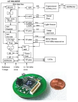
3.1. HARDWARE
ORGANISATION
International Journal of Research (IJR)
e-ISSN: 2348-6848, p- ISSN: 2348-795X Volume 2, Issue 05, May 2015Available at http://internationaljournalofresearch.org
interrupt logic necessary for wake-up and power save which is similar to power down, but leaves a timer also running. The sensors use Analog to Digital Converters to communicate data to the processor.
Three LEDs represent outputs connected through general I/O ports; they may be used to display digital values or status. The photosensor represents an analog input device with simple control lines. In this case, the control lines eliminate power drain through the photo resistor when not in use. The input signal can be directed to an internal ADC in continuous or sampled modes.
The radio is the most important component. It represents an asynchronous input/output device with hard real time constraints. It consists of an RF Monolithics 916.50MHz transceiver (TR1000), antenna, and collection of discrete components to configure the physical layer characteristics such as signal strength and sensitivity. It operates in an ON-OFF key mode at speeds up to 19.2Kbps. Control signals configure the radio to operate in either transmit, receive, or power-off mode. The radio contains no buffering so each bit must be serviced by the controller on time. Additionally, the transmitted value is not latched by the radio, so jitter at the radio input is propagated into the transmission signal.
The temperature sensor (Analog Devices AD7418) represents a large class of digital sensors which have internal A/D converters and interface over a standard chip-to-chip protocol. The serial port represents an important asynchronous bit-level device with byte-level controller support. It uses I/O pins that are connected to an internal UART controller. In transmit mode, the UART takes a byte of data and shifts it out serially at a specified interval. In receive mode, it samples the input pin for a transition and shifts in bits at a specified interval from the edge. Interrupts are triggered in the processor to signal completion events. The coprocessor represents a synchronous bit-level device with byte-level support. In this case, it is a very limited MCU (AT90LS2343, with 2 KB ash instruction memory, 128 bytes of SRAM and
EEPROM) that uses I/O pins connected to an SPI controller. SPI is a synchronous serial data link, providing high speed full-duplex connections (up to 1 Mbit) between various peripherals. The coprocessor is connected in a way that allows it to reprogram the main microcontroller. The sensor can be reprogrammed by transferring data from the network into the coprocessor's 256 KB EEPROM (24LC256). Alternatively the main processor can use the coprocessor as a gateway to extra storage.
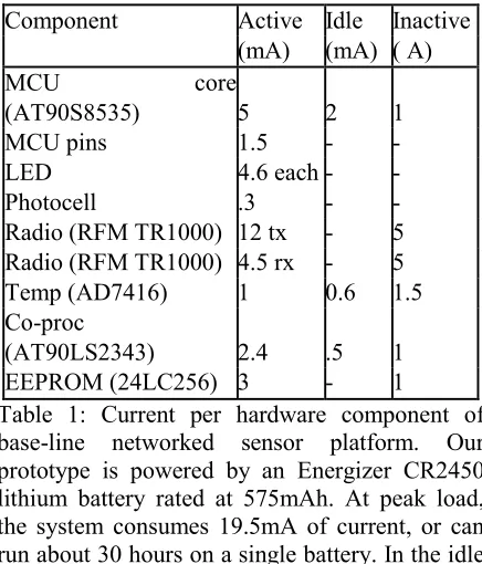
3.2. POWER CHARACTERSTICS
Table1 shows the current drawn by each hardware component under three scenarios: peak load when active, load in “idle” mode, and inactive. When active, the power consumption of the LED and radio reception are about equal to the processor. The processor, radio, and sensors running at peak load consume 19.5mA at 3 volts, or about 60mW. This figure should be contrasted with the 10A current draw in the inactive mode. Clearly, the biggest savings are obtained by making unused components inactive whenever possible. The system must embrace the philosophy of getting the work done as quickly as possible and going to sleep.
Component Active Idle Inactive (mA) (mA) ( A) MCU core
(AT90S8535) 5 2 1 MCU pins 1.5 - - LED 4.6 each - - Photocell .3 - - Radio (RFM TR1000) 12 tx - 5 Radio (RFM TR1000) 4.5 rx - 5 Temp (AD7416) 1 0.6 1.5 Co-proc
(AT90LS2343) 2.4 .5 1 EEPROM (24LC256) 3 - 1
International Journal of Research (IJR)
e-ISSN: 2348-6848, p- ISSN: 2348-795X Volume 2, Issue 05, May 2015Available at http://internationaljournalofresearch.org
mode, the system can run for 200 hours. When switched into inactive mode, the system draws only 10 A of current, and a single battery can run for over a year.
The minimum pulse width for the RFM radio is 52s. Thus, it takes on the order of 1.9J of energy to transmit a single bit 1 and on the order of 0.5J of energy to receive a bit. During this time, the processor can execute 208 cycles (roughly 100 instructions) and can consume up to 0.8J. A fraction of this instruction count is devoted to bit level processing. The remainder can go to higher level processing (byte-level, packet level,
application level) amortized over several bit times. Unused time can be spent in idle or power-down mode.
To broaden the coverage of our study, we deploy these networked sensors in two configurations. One is a mobile sensor that picks up temperature and light readings and periodically presents them on the wireless network as tagged data objects. It needs to conserve its limited energy. The second is a stationary sensor that bridges the radio network through the serial link to a host on the Internet. It has power supplied by its host, but also has more demanding data flows.
International Journal of Research (IJR)
e-ISSN: 2348-6848, p- ISSN: 2348-795X Volume 2, Issue 05, May 2015Available at http://internationaljournalofresearch.org
4.1.TINY
MICROTHREADING
OPERATING
SYSTEM (TinyOS)
The core challenge we face is to meet the requirements for networked sensors put forth in Section 2 upon the class of platforms represented by the design in Section 3 in manner that scales forward to future technology. Small physical size, modest active power load and tiny inactive load are provided by the hardware design. An operating system framework is needed that will retain these characteristics by managing the hardware capabilities effectively, while supporting concurrency intensive operation in a manner that achieves efficient modularity and robustness.
Our system is designed to scale with the current technology trends supporting both smaller, tightly integrated designs as well as the crossover of software components into hardware. This is in contrast to traditional notions of scalability that are centered on scaling up total power resources work for a given computing paradigm. It is essential that network sensor architectures plan for the eventual integration of sensors, processing and communication. The days of sensor packs being dominated by interconnect and support hardware, as opposed to physical sensors, are numbered.
In TinyOS, we have chosen an event model so that high levels of concurrency can be handled in a very small amount of space. A stack-based threaded approach would require that stack space be reserved for each execution context. Additionally, it would need to be able to multi-task between these execution contexts at a rate of 40,000 switches per second, or twice every 50s - once to service the radio and once to perform all other work. It is clear that an event-based regime lends itself to these requirements. It is not surprising that researchers in the area of high performance computing have seen this same phenomena- that event based programming must be used to achieve high performance.
In this design space, power is the most precious resource. We believe that the event-based approach creates a system that uses CPU resources efficiently. The collection of tasks
associated with an event are handled rapidly, and no blocking or polling is permitted. Unused CPU cycles are spent in the sleep state as opposed to actively looking for an interesting event. Additionally, with real-time constraints the calculation of CPU utilization becomes simple- allowing for algorithms that adjust processor speed and voltage accordingly.
4.2. TinyOS Design
TinyOS uses an Event model so that high levels of concurrency can be handled in a very small amount of space unlike the stack based threaded approach that uses too much stack space and also has a high context switch time.
Since Power is a precious resource, CPU resources must be utilized efficiently. The event-based approach handles tasks associated with events rapidly without allowing blocking or polling. Unused CPU cycles are spent in sleep state as opposed to actively looking for events. TinyOS was developed in C.
Components, Commands, Events and Tasks
TinyOS is divided into a collection of Software Components. A TinyOS application consists of a scheduler and a graph of components describing their interaction.
A Component has four parts: a set of Command Handlers, a set of Event Handlers, an encapsulated fixed size frame and a bundle of simple tasks. Each component declares the commands it uses andevents it signals.
The fixed sized frames are statically allocated which helps to know the memory requirements of a component at compile time. The frame is an internal storage space that contains the state of the component and is used by the events, commands and tasks.
International Journal of Research (IJR)
e-ISSN: 2348-6848, p- ISSN: 2348-795X Volume 2, Issue 05, May 2015Available at http://internationaljournalofresearch.org
that are application specific. The higher-level components issue commands to lower-level components while the lower ones signal events to the higher-level components. Hence we can think of the component to have an upper interface, which names the commands it implements and the events it signals a lower interface which names the commands it uses and events it handles.
Commands are non-blocking requests made to lower level components. A command will deposit request parameters into its frame and conditionally post a task for a later execution. It also provides feedback to its caller (from a higher level component) by returning status of success or failure.
Event Handlers are invoked to deal with Hardware events either directly or indirectly. The lowest level components have handlers connected directly to hardware interrupts. An event Handler can deposit information in its frame, post tasks, signal higher-level events or call lower level commands. Events help in forwarding changes upwards while commands forward processing downwards. In order to avoid cycles, command cannot signal events.
Tasks perform the work and are atomic with respect to other tasks. They run to completion and can call lower commands, signal higher-level events and schedule other tasks within the same component. The run-to completion property helps to allocate a single stack to the currently executing task and this conserves space. Tasks also allow concurrency within each component as they execute asynchronously. They must never block to avoid delaying progress in other components. Hence we can look at these tasks as blocks of computation.
The Task scheduler is a simple FIFO scheduler that has a bounded size scheduling data Structure.
It is power sensitive and puts the processor to sleep when the task queue is empty, but leaves the peripherals operating to wake up the system in case of any new hardware event. There is a two level scheduling hierarchy in the TinyOS – events preempt tasks but tasks do not preempt other tasks. Since all components have bounded storage, a component has to refuse commands.
4.3. Example Component
A typical component including a frame, event handlers, commands and threads for a message handling component is pictured in Figure 2. Like most components, it exports commands for initialization and power management. Additionally, it has a command for initiating a message transmission, and signals events on the completion of a transmission or the arrival of a message. In order to perform its function, the message component issues commands to a packet level component and handles two types of events: one that indicates a message has been transmitted and one that signals that a message has been received.
Since the components describe both the resources they provide and the resources they require, connecting them together is very simple. The programmer simply matches the signatures of events and commands required by one component with the signatures of events and commands provided by another component. The communication across the components takes the form of a function call, which has low overhead and provides compile time type checking.
4.4. TYPES OF COMPONENT
International Journal of Research (IJR)
e-ISSN: 2348-6848, p- ISSN: 2348-795X Volume 2, Issue 05, May 2015Available at http://internationaljournalofresearch.org
component exports commands to manipulate the individual I/O pins connected to the RFM transceiver and posts events informing other components about the transmission and reception
of bits. Its frame contains information about the current state of the component (the transceiver is in sending or receiving mode, the current bit rate, etc.). The RFM consumes the
Figure 2: A sample messaging component. Pictorially, we represent the component as a bundle of threads, a block of state (component frame) a set of commands (upside-down triangles), a set of handlers (triangles), solid downward arcs for commands they use, and dashed upward arcs for events they signal. All of these elements are explicit in the component code.
hardware interrupt, which is transformed into either the RX_bit_evt or into the TX_bit_evt. There are no tasks within the RFM because the hardware itself provides the concurrency. This model of abstracting over the hardware resources can scale from very simple resources, like individual I/O pins, to quite complex ones, like UARTs.
Synthetic hardware components simulate the behavior of advanced hardware. A good example of such component is the Radio Byte component (see Figure.3). It shifts data into or out of the underlying RFM module and signals when an entire byte has completed. The internal tasks perform simple encoding and decoding of the data. Conceptually, this component is an enhanced state machine that could be directly cast into hardware. From the point of view of the higher levels, this component provides an interface and functionality very similar to the UART hardware abstraction component: they provide the same commands and signal the same
events, deal with data of the same granularity, and internally perform similar tasks (looking for a start bit or symbol, perform simple encoding).The high level software components perform control, routing and all data transformations. A representative of this class is the messaging module presented above, in Figure 2. It performs the function of filling in a packet buffer prior to transmission and dispatches received messages to their appropriate place. Additionally, components that perform calculations on data or data aggregation fall into this category.
International Journal of Research (IJR)
e-ISSN: 2348-6848, p- ISSN: 2348-795X Volume 2, Issue 05, May 2015Available at http://internationaljournalofresearch.org
5. EVALUATION
Small Physical Size
The source code size for various components of the TinyOS system and the sample Multi hop routing application is shown below. The important TinyOS component „scheduler‟ occupies only 178 Bytes. The data size of the scheduler is only 16 bytes and it utilizes only 3% of the available data memory.
Software Footprint refers to the total number of bytes occupied by a software component on the device. The Active Message Layer occupies a total of 322 Bytes. The total device Binary is 2.6 Kbytes and includes the packet level, byte level and bit level controllers, the AM component and the routing Application. 40 Bytes is used for static data. Hence the software footprint of the TinyOS is very small and this is very useful when memory is strictly constrained.
Component Name Code Size (bytes) Data Size (bytes) Multihop router AM_dispatch AM_temperature AM_light AM Packet Radio_byte RFM Photo Temperature UART UART_packet I2C_bus 88 40 78 146 356 334 810 310 84 64 196 314 192 0 0 32 8 40 40 8 1 1 1 1 40 8 Processor_init TinyOS Scheduler C runtime 172 178 82 30 16 0 Total 3480 226
Table 2. Code & Data size for TinyOS and an application
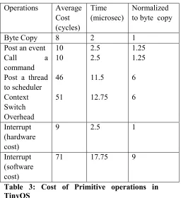
Concurrency-Intensive Operations
Network Sensors need to handle multiple flows of information simultaneously. An important characteristic is the context switch speed. The table below shows this aspect when compared to the hardware cost for moving bytes in memory. The cost of propagating an event is roughly equivalent to that of copying one byte of data. Posting a thread and switching context costs
about as much as moving 6 bytes of memory. Hence the TinyOS supports concurrency intensive operations effectively due to reduced context switch time.
Operations Average Cost (cycles)
Time (microsec)
Normalized to byte copy
Byte Copy 8 2 1 Post an event
Call a command Post a thread to scheduler Context Switch Overhead 10 10 46 51 2.5 2.5 11.5 12.75 1.25 1.25 6 6 Interrupt (hardware cost)
9 2.5 1
Interrupt (software cost)
71 17.75 9
Table 3: Cost of Primitive operations in TinyOS
Efficient Modularity
International Journal of Research (IJR)
e-ISSN: 2348-6848, p- ISSN: 2348-795X Volume 2, Issue 05, May 2015Available at http://internationaljournalofresearch.org
Communications Model Evaluation
The performance of the Active message model can be evaluated by using Round Trip Time (RTT) and throughput.
The RTT measures the time for a message to be sent from a Host PC to a specific sensor device and back. The RTT is plotted for various route lengths. A route length of one measures the Host-PC to base station RTT and is about 40ms. This reflects the cost of wired link, device processing and Host OS overhead. For routes greater than one hop, the RTT also includes the latency of the wireless link
between two devices. The difference between the two and one hop RTT yields the device-to-device RTT of 78ms.These RTT measures indicate that the Tiny Active message Model is really fast.
Since the RTT is very less, the throughput or the messages handled in unit time is more.
6. Comparison of TinyOS with
other Embedded OS
Comparison of TinyOS with common Desktop and Server OS like MS-Windows, Sun Solaris, UNIX or IBM‟s AIX is not meaningful as their application environments are totally different. These Desktop OS are meant for a broad range of applications and really not suited for small-embedded devices, whereas TinyOS is suited only for Networked Sensors that are embedded in a Data collection Network.
However we can compare TinyOS with some of the real time operating systems like VxWorks, WinCE, PalmOS and QNX that are also meant for embedded devices. Many of these are based on Micro kernels that allow for capabilities to be added or removed based on system needs. These systems provide memory protection and fault isolation features that TinyOS doesn‟t provide. Security of applications is very important in larger commercial systems. Tiny OS design does not incorporate security features at all. But still security may not be that important an issue in Data collection Networks and situation monitoring.
TinyOS does not guarantee 100% packet delivery, as it has no time-out mechanism and receipt acknowledgement features. It is found that about 5% of the bytes received were corrupted even after some error correction. Hence some newer error correction scheme with CRC check is required.
International Journal of Research (IJR)
e-ISSN: 2348-6848, p- ISSN: 2348-795X Volume 2, Issue 05, May 2015Available at http://internationaljournalofresearch.org
in the hundreds of Kilobytes.
There is also a collection of smaller real time OS like Creem, pOSEK and Ariel that are minimal OS designed for deeply embedded systems such as motor controllers or Microwave ovens. They also have severely constrained storage and execution models. But their models tend to be Control Centric that is controlling access to hardware resources as opposed to TinyOS‟s Data flow centric approach. Even the pOSEK, that meets TinyOS‟s memory requirements, exceeds the context switch limitations and hence cannot meet real-time requirements. There is no preemption in Creem and this totally prevents real time processing.
Most of these OS are based on a Thread based Model and these systems need to reserve additional storage for every thread created. Though there might be better separation of work using threads, the storage penalty is too much. On the other hand TinyOS is an event based model and because of good buffer management, it does well on storage constraints.
The TinyOS‟s Active message model helps a lot in the reduction of power consumption. Sensors can switch to a power save mode when they are not active and events would trigger them to come back into normal-operational mode. The other threaded models have to keep polling for some event to occur. This results in considerable power consumption. Another advantage of using events is that polling based I/O mechanisms see significant performance degradation when the number of interfaces that must be periodically checked increases.
A traditional socket based TCP/IP communication model (used by MS-Windows and Unix) is not optimal for the Networked Sensors. First of all the use of a socket model forces the system into a thread based programming model. This is because sockets have a stream-based interface where the user application polls or blocks as it waits for data to arrive. The overhead associated with context switches and the storage of inactive execution contexts is too much in the case of these socket models.
Secondly, the communication is extremely
expensive for network sensors and it is advantageous to transmit as few bits as possible. In TCP/IP and UDP, there are different fields that come as an overhead like sequence numbers, addresses, port numbers, protocol types etc. A single TCP/IP packet has an overhead of 48 Bytes.
Finally the TCP/IP protocol has a lot of overhead in the memory management associated with a stream based interface. The networking stack must buffer incoming data until the application requests it, whereupon it must be copied into the application's buffer while any remaining data remains buffered by the protocol stack. This buffer management greatly increases complexity and overhead. Creation of intermediate copies & data fragmentation proves too costly for the sensors.
There is an assortment of OS such as VxWorks, OS-9, PalmOS and QNX that provide TCP/IP based network connectivity to embedded devices. However, these real time OS consume significantly more resources than that are currently available on the class of hardware that TinyOS works with.
Small Devices like Palm Pilots and PDA‟s (using PalmOS) are optimized for user response times. They have quick periods of very high activity and long periods of idle time. Networked Sensor regimes have long periods of constant data collection.
The Wireless Application Protocol (WAP) addresses many of the same wireless device issues presented in this paper (e.g. power and CPU constraints). However, WAP is targeted mainly at client server type applications. Networked Sensor domain has small autonomous devices that may operate in large numbers.
International Journal of Research (IJR)
e-ISSN: 2348-6848, p- ISSN: 2348-795X Volume 2, Issue 05, May 2015Available at http://internationaljournalofresearch.org
Messages may not be really suitable for other traditional computing environments.
7. Commercial Applications and
Future Research Directions
The various applications of these Networked Sensors and Tiny OS are:
1) Personnel Tracking and information distribution
2) Monitoring of Real-time environments and Data collection like Temperature, light, pressure etc.
3) Secure Messaging that requires trusted communication to bases using RC5 cryptography.
4) Studying Life Science patterns such as Bird‟s Migration and retrieving ecological parameters like toxic contents in a river.
5) Monitoring Enemy targets and other targets of importance
Crossbow Inc. and UC Berkeley‟s Computer Science Department are commercializing microsensor Modes, that help in detecting and monitoring a wide variety of targets such as an enemy personnel or chemical threats. TinyOS would be used in these Motes. Crossbow manufactures and sells the Networked Sensor hardware using TinyOS.
The department of Computer Science, UC-Berkeley released a new version of TinyOS 0.6 on January 31, 2002. It can be installed over Windows 2000 and Red Hat Linux platforms. Intel has opened a new R&D laboratory in Berkeley, California that focuses on Pro-active computing technologies. This includes the Mote project and further development of TinyOS. Some of the Future Research Works in TinyOS are:
1) Development of a better MAC layer that fits the requirements of Network Sensors.
2) Incorporating Security features in Data Transmission using RC5 cryptography and some form of Memory protection schemes 3) Determine all possible limitations of TinyOS 4) Incorporate TinyOS to newer Hardware Architectures
5) Develop techniques to deliver data more reliably and reduce data corruption.
7. CONCLUSION
The TinyOS approach has proven quite effective in supporting general purpose communication among potentially many devices that are highly constrained in terms of processing, storage, bandwidth, and energy with primitive hardware support for I/O. Efficiency and low energy use and modularity is taking precedence over FLOPS and throughput.
Its event driven model facilitates interleaving the processor between multiple flows of data and between multiple layers in the stack for each flow while still meeting the severe real-time requirements. Since storage is very limited, it is common to process messages incrementally at several levels, rather than buffering entire messages and processing them level-by-level.
By adopting a non-blocking , event-driven approach, TinyOS avoids supporting traditional threads, with the associated multiple stacks and complex synchronization support. The component approach has yielded not only robust operation despite limited debugging capabilities, it has greatly facilitated experimentation.
8. REFRENCE
[1.] Jason Hill, Robert Szewczyk, Alec Woo, Seth Hollar, David Culler, and Kristofer Pister. “System architecture directions for networked sensors”. In Proceedings of the Ninth International Conference on Architectural Support for Programming Languages and Operating Systems, Cambridge, MA, November 2000.
[2.] David E. Culler, Jason Hill, Philip Buonadonna, Robert Szewczyk, and Alec Woo.
[3.] “A Network-Centric Approach to Embedded Software for Tiny Devices”. In Proceedings of the International Workshop on Embedded Systems (EMSOFT) 2001: Tahoe City, CA, USA, October 2001
International Journal of Research (IJR)
e-ISSN: 2348-6848, p- ISSN: 2348-795X Volume 2, Issue 05, May 2015Available at http://internationaljournalofresearch.org
submitted to the Department of Electrical Engineering and Computer Sciences, University of California at Berkeley, December 2000
[5.] Philip Buonadonna, Jason Hill, David Culler. “Active Message Communication for Tiny Networked Sensors”. In Proceedings of the IEEE conference Infocom 2001, Anchorage, Alaska, April 2001
[6.] The Official TinyOS Project Website at University of California, Berkeley. http://tinyos.millennium.berkeley.edu/
[7.] Presentation Slides on “A System Architecture for Networked Sensors“ http://tinyos.millennium.berkeley.edu/presentati ons/ASPLOS_2000.ppt
[8.] Presentation Slides on “ How to use TinyOS”
http://tinyos.millennium.berkeley.edu/presentati ons/TinyOS.ppt
[9.] Presentation Slides on “ Towards System Architecture for Tiny Networked Devices”
http://tinyos.millennium.berkeley.edu/presentati ons/TinyOSTalk.ppt
[10.] Presentation Slides on “ TinyOS – Communication and Computation at the extremes”
http://tinyos.millennium.berkeley.edu/presentati ons/Ninja_Retreat_highlight_2001.ppt
[11.] The TinyOS Software Website. http://webs.cs.berkeley.edu/tos/
[12.] The Abstract Web-page on TinyOS: Operating System for Sensor Networks http://buffy.eecs.berkeley.edu/IRO/Summary/01 abstracts/szewczyk.1.html