Implementation and Control of Hybrid Multilevel Converter with
Floating Dc-Link for Current Waveform Improvement
B. SHIVAJI M.TECH (P.HD) ASST PROFESSOR DEPT OF EEE KITS ENGG COLLEGE,KODAD
E. KRISHNAVENI- 13QU1A0222 IV B.TECH EEE
KITS ENGG COLLEGE ,KODAD
M. MAMATHA-13QU1A0227 IV B.TECH EEE
KITS ENGG COLLEGE ,KODAD
Abstract —
Multilevel converters offer advantages in terms of the output waveform quality due to the increased number of levels used in the output voltage modulation. This advantage is particularly true for cascaded H-bridge converters that can be built to produce a large number of levelsthanks to their modular structure.
Nevertheless, this advantage comes at the cost of multiple DC- links supplied by independent rectifiers through the use of a multi-output transformer for inverters. This frontend complicates the implementation of converters that have a high number of levels. An alternative method of using lower voltage cells with floating dc-links to compensate only for voltage distortion of an NPC converter is considered for active
rectifier applications. The analogy between the floating H-bridges and series active filters is used to develop a strategy for harmonic compensation of the NPC output voltage and the control of the floating dc-link voltages. This simplifies the current control scheme and increases its bandwidth. Experimental results with a low power prototype that show the good performance of the proposed modulation technique and the resulting improvement in the output waveform are provided.
INDEX TERMS-power electronics, current control , harmonic distortion
1.INTRODUCTION:
achieve a three-level waveform, a single full-bridge inverter is employed. Basically, a full-bridge inverter is known as an H-bridge cell, which is illustrated in Fig. 1.1. The inverter circuit consists of four main switches and four freewheeling diodes.
.
Figure 1 An H-bridge cell.
1
.1 Gate Signal and Inverter
Operation
According to four-switch
combination, three output voltage levels, +V, -V, and 0,can be synthesized for the voltage across A and B. During inverter operation shown in Fig. 1.2, switch of S1 and S4 are closed at the same time to provide VAB a positive value and a current path for Io. Switch S2 and S4 are turned on to provide VAB a negative value with a path for Io. Depending on the load current angle,
the current may flow through the main switch or the freewheeling diodes. When all switches are turned off, the current will flow through the freewheeling diodes.
2 CASCADE H-BRIDGE
INVERTER
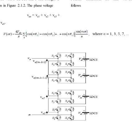
A single-phase structure of an m-level cascaded inverter is illustrated in Figure 31.1. Each separate dc source (SDCS) is connected to a single-phase full-bridge, or H-full-bridge, inverter. Each inverter level can generate three different voltage
outputs, +Vdc, 0, and –Vdc by connecting the
dc source to the ac output by different
combinations of the four switches, S1, S2, S3,
and S4.
To obtain +Vdc, switches S1 and S4
are turned on, whereas –Vdc can be obtained
by turning on switches S2 and S3. By turning
sources. An example phase voltage waveform for an 11-level cascaded H-bridge inverter with 5 SDCSs and 5 full bridges is shown in Figure 2.1.2. The phase voltage
van = va1 + va2 + va3 + va4 + va5.
For a stepped waveform such as the one depicted in Figure 31.2 with s steps, the Fourier Transform for this waveform follows
Fig 3. Output phase voltage waveform of an 11-level cascade inverter with 5 separate dc sources.
The magnitudes of the Fourier coefficients when normalized with respect to Vdc are as follows:
The conducting angles, θ1, θ2, ..., θs, can be chosen such that the voltage total harmonic distortion is a minimum. Generally, these angles are chosen so that predominant lower frequency harmonics, 5th, 7th, 11th, and
13th, harmonics are eliminated. More detail
on harmonic elimination techniques will be presented in the next section.
Multilevel cascaded inverters have been proposed for such applications as static
VAR generation, an interface with
renewable energy sources, and for battery-based applications. Three-phase cascaded inverters can be connected in star, as shown
in Figure 2.1.3, or in delta. Peng has
demonstrated a prototype multilevel
cascaded static VAR generator connected in parallel with the electrical system that could supply or draw reactive current from an electrical system. The inverter could be controlled to either regulate the power factor of the current drawn from the source or the bus voltage of the electrical system where the inverter was connected.
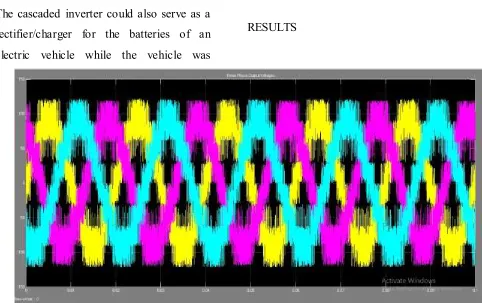
Cascaded inverters have also been proposed for use as the main traction drive in electric vehicles, where several batteries or ultra capacitors are well suited to serve as SDCSs. The cascaded inverter could also serve as a rectifier/charger for the batteries of an electric vehicle while the vehicle was
connected to an ac supply as shown in Figure 2.3 Additionally, the cascade inverter can act as a rectifier in a vehicle that uses regenerative braking.
RESULTS
CONCLUSION
This paper has presented the series connection of a SHE modulated NPC and an HB multilevel inverter with a novel control scheme to control the floating voltage source of the HB stage. The addition of the HB series active filter or additional converter stage is not intended to increase the power rating of the overall converter.
Rather, the main goal is to improve, in a controllable or active way, the power quality of the NPC bridge .
which may have a relatively low
use of smaller inductive filters when connecting to the utility supply in AFE applications. hence no changes are made to the power circuit and modulation stage of the NPC inverter, the series HB power circuit and its control scheme can be easily added as an upgrade to the existing NPC-driven applications. The proposed series HB filter control scheme can be used either as a grid or load interface, depending on whether the NPC converter is used as an AFE or an inverter, respectively. Both possibilities can be combined if used in a back-to-back configuration. The proposed floating dc-link voltage control scheme can be adapted to other hybrid topologies or CHB converters with the advantage that the isolated input transformers can be avoided.
REFERENCES
[1] J. Rodríguez, S. Bernet, B. Wu, J. Pontt, and S. Kouro, “Multilevel voltage-source-converter topologies for industrial
medium-voltage drives,” IEEE Trans. Ind. Electron.,
vol. 54, no. 6, pp. 2930–2945, Dec. 2007.
[2] S. Kouro, M. Malinowski, K. Gopakumar, J. Pou, L. Franquelo, B. Wu, J. Rodríguez, M. Pérez, and J. León, “Recent advances and industrial applications of
multilevel converters,” IEEE Trans. Ind.
Electron., vol. 57, no. 8, pp. 2553–2580, Aug. 2010.
[3] J. S. Lai and F. Z. Peng, “Multilevel converters—A new breed of power converters,” IEEE Trans. Ind. Appl., vol. 32, no. 2, pp. 509–517, May/Jun. 1996.