© 2015, IRJET.NET- All Rights Reserved
Page 324
High Speed Non-Linear Carry Select Adder
D.Srimathi
1, G.N.Jayabhavani
21
M.E, Applied Electronics, IFET College Of Engineering, Tamilnadu, India
2Assistant Professor,ECE , IFET College Of Engineering,Tamilnadu, India
---***---Abstract -
The role of adder in addition process issignificant. The addition operation can be performed by numerous adder. Nowadays the modern world requires fast adders. This requirement can be fulfill by Carry select adder. The main operation of carry select adder depends upon the input carry value. The structure of CSLA can be altered to improve its performance. It can execute quick arithmetic operations. The Modified Non-linear (NON-LINEAR) carry select adder (CSLA) is formed by altering the structure of Conservative Non-linear carry select adder. The carry selection and final sum generation process is different when compared to the Conservative Non-linear carry select adder(CSLA) and Non-linear binary to excess-1 convertor(BEC) carry select adder. In the proposed work the utilization of logical elements and delay is comparatively less. Due to this the performance of adder is also improved.
Key Words:
Adder, Non-linear binary to excess-1convertor, Modified Non-linear carry select adder, Conservative Non-linear(NON-LINEAR) carry select adder, carry select adder(CSLA)
I.INTRODUCTION
Adders are used in numerous fields. The requirement of digital world is simple, fast, low cost design of adders. The efficiency of adder can be improved by increasing its performance. The ripple carry adder (RCA) can be formed by placing the full adders in series manner. Its operation fully depends upon the previous stage carry value. It consumes more time to compute an operation. It is a one of the disadvantage of Ripple carry adder. To overcome this problem a new adder has been designed which is known as Conservative carry select adder . The ripple carry adder act as a building blocks of conservative carry select adder. Its working principle also depend upon the input carry value. The working of Conservative carry select adder is clearly explained in paper[1].In which 3-bit adder requires 3 input. The first 2 input values are
acquired from A and B. While the input carry value will act as a third input. Based on the third input value the sum and carry out is produced. Even though it provide a better results It consists of several redundant operations .To eliminate this problem conservative Non-linear carry select adder is designed. The propagation delay indicate that the time taken to reach the data from one block to another block which can be achieved with the help of Non-linear CSLA so it is well suited for higher order bit widths. This process can be clearly explained in paper[2]. Even though conservative Non-linear carry select adder is better than conservative carry select adder its architecture is not desirable. Again to improve the performance of adder a new adder is proposed which is known as Non-linear BEC carry select adder. The throughput of Non linear BEC carry select adder has less delay. The efficiency can be improved by using the Non-linear architecture in BEC carry select adder[3].In the proposed scheme the number of XOR gates used has been reduced and the carry has been selected earlier to the sum production which reduces the delay. When compared to the existing system less logical operations is used in proposed scheme. The paper is structured as following below. The explanation of Conventional carry select adder is provided in section II. The information about non linear BEC carry select adder is demonstrated in Section III. The detail about the proposed work is exhibited in Section IV .The Test results were shown in section V. Section VI tells about the conclusion and future work.
II. CONSERVATIVE NON-LINEAR CSLA
© 2015, IRJET.NET- All Rights Reserved
Page 325
more number of combinational elements so it isconsidered as a less significant
.
Fig.1.1 Structure of Ripple carry adder
Fig 1.1 symbolize the structure of Ripple carry adder (RCA).In the below equation S represents Sum while C represents Carry.
S = A ^ B ^ Cin (1)
C = (A.B) + Cin(A+B) (2)
The equation (1) and (2) elucidate the formation of sum and carry.
Fig. 1.2 Structure of 128 Bit Conservative Non-linear CSLA
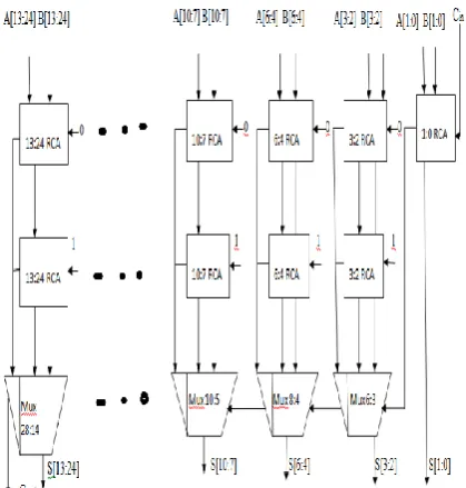
Fig1.2 signifies the Conservative Non-linear carry select adder (CSLA) structure. It explains how the operation is performed in each section.
III.NON-LINEAR BEC CSLA
The structure of Non-linear BEC carry select adder is obtained by modifying the second stage of Conservative carry select adder. The structure of second stage Non-linear BEC carry select adder is shown below. The operation of second stage is to increase the sum value by 1.It can perform this operation with less delay. The second stage block and multiplexer is placed parallel to the first stage which is present in the Conservative carry select adder. The second stage received the sum and carry out of the first stage it compute the operation and produce the sum and carry for its stage. It will ascend the input value by one. If the select line value of mux=0 the first stage sum and carry has been produced .Suppose the select line value=1 the second stage sum and carry will be taken as a final stage output.
Z0=~C0 (3)
Z1=C0 ^ C1 (4)
Z2=C2 ^ (C0&C1) (5)
Z3=C3 ^ (C0&C1&C2) (6)
Fig.2.1 Structure of Binary to Excess-1 Convertor
© 2015, IRJET.NET- All Rights Reserved
Page 326
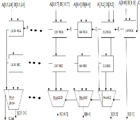
Fig 2.2 Structure of 128 Bit BEC based Non-linearCSLA
The parameters Z0, Z1, Z2 represent the sum of a BEC unit while Z3 represent the carry out of a BEC unit. Fig 2.2 show the construction of non linear BEC carry select adder.
IV.PROPOSED NON-LINEAR CSLA
The goal of proposed technique is to improve the performance of adder. By reducing the utilization of large number of gates the area get reduce. In existing techniques more number of XOR gates were used. An XOR gate is a combination of 2 AND, 2NOT and 1 OR gates. So it can occupy large number of space. Due to this the time taken to compute the operation will also high. To eliminate this problem instead of XOR gate combination of AND, OR gates are used which can perform the same operation as that of XOR gate. By performing the XOR operation between A an B the partial sum and carry is generated. The carry C1 and C2 are produced by using the partial sum and carry. According to the input carry value one of the carry is chosen as a final carry. The carry out has been obtained from the most significant bit of C. The XOR operation play a major role to produce MSB bits of final-sum (Sf). It is perform in between the most significant bit of partial sum and least significant bit of carry. The Xor operation is made between input carry and remaining bit of partial sum to obtain the remaining of final sum(Sf).
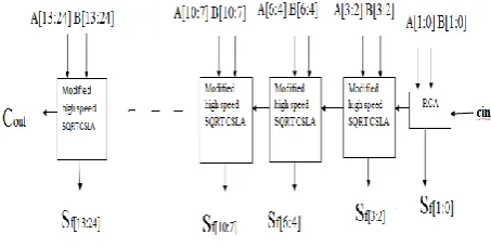
. Fig 3.1 Block diagram of Non-linear Modified CSLA
Sp(i ) =A(i)^B(i) (7)
Cp(i) =A(i).B(i) (8)
CO0(i) =C1(i-1).Sp(i-1)+Cp(i) where C1(0)=0 (9) CO1(i) =C2(i-1).Sp(i-1)+Cp(i) whereC2(0)=0 (10)
C1(i)=CO0(i) when(Cin=0) (11)
C2(i)=CO1(1)when(Cin=1) (12)
Cout=C(n-1) (13)
Sf(0)=Sp(0)^Cin (14)
Sf(i)=Sp(n-1)^C(i-1) (15)
© 2015, IRJET.NET- All Rights Reserved
Page 327
Fig 3.2 Structure of Modified Non-linear CSLA
Fig. 3.2 portrays how the operation is performed in Modified Non-linear CSLA. The significant of this technique is prior carry selection.
V. TEST RESULTS
The Verilog HDL language is used to implement the proposed work in QUARTUS II 9.1 software. The subsequent result show the performance variation between the existing and proposed work through its area and delay.
Fig.4.1 Logical elements utilization of Non-linear Conservative CSLA
Fig 4.1 demonstrates the utilization of number of gates. Out of 38000 logical elements it acquired only 387 elements.
Fig 4.2 Delay of Non-linear Conservative CSLA
Fig 4.2 reveal about the excess time taken to compute a operation.
Fig 4.3 Logical elements utilization of Non-linear BEC CSLA
Fig 4.3 convey about the number of gates consumed. Out of 38000 logical elements it acquired only 364 logical gates.
Fig. 4.4 Delay of Non-linear BEC CSLA
© 2015, IRJET.NET- All Rights Reserved
Page 328
Fig 4.5 Logical elements utilization of Modified Non- linear CSLAFig 4.5 convey the number of gates consumed. Out of 38000 logical elements it acquired only 308 gates.
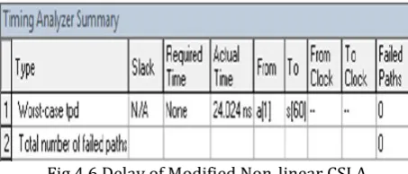
Fig 4.6 Delay of Modified Non-linear CSLA
Fig 4.6 describes about the extreme time taken to fulfill a operation.
TABLE.1 COMPARISON BETWEEN EXISTING
AND PROPOSED METHODS
.DESIGN
WIDTH
AREA DELAY(ns)
CONSERVATIVE NON-LINEAR CSLA
128
387
63.309
BEC BASED NON-LINEAR CSLA
128
364
56.764
MODIFIED NON-LINEAR CSLA
128
308
24.024
The Table.1 shown that the difference between Area and Delay of Proposed method and Existing Methods.