R E S E A R C H
Open Access
SINR-based scheduling in multi-path
multi-hop multi-radio multi-channel mmWave
WPANs
Yunfeng Liu
1, Zhiyong Feng
1*, Zhiqing Wei
1and Zebing Feng
2Abstract
Millimeter wave (mmWave) communications is a prospective candidate technology for multi-gigabit rates multimedia applications. To combat the severe propagation attenuation of mmWave, the high gain directional antenna is commonly employed at the nodes. Moreover, exploiting multiple radios over multiple channels is also a promising technology to improve the throughput and delay performance of mmWave communications. In this paper, considering the signal to interference plus noise ratio (SINR) constraint, we develop a multi-path multi-hop multi-radio multi-channel (MPMH-MRMC) concurrent transmission scheduling algorithm to fully exploit spatial reuse in mmWave wireless personal area
networks (WPANs). The problem of MPMH-MRMC scheduling is formulated as a mixed-integer linear programming (MILP) to clear all the flows within a minimum number of time slots, which is generally NP-hard. We further propose a heuristic MPMH-MRMC scheme with low computational complexity to solve the problem. Finally, through extensive simulations, we demonstrate that MPMH-MRMC can significantly improve the network performance in terms of network throughput and transmission delay under various traffic patterns.
Keywords: Multi-path multi-hop (MPMH) scheduling, Multi-radio multi-channel (MRMC) network, Spatial reuse, Wireless personal area networks (WPANs)
1 Introduction
Over the past decade, Millimeter wave (mmWave) com-munications in the 60 GHz band has gained consider-able attention from academia, industry, and standards bodies. Due to the unprecedented 7 GHz unlicensed spectrum, mmWave communications is able to sup-port multi-gigabit wireless multimedia services, such as uncompressed high-definition TV, instantaneous music, and image data transmission. With the recent advances in mmWave transceivers design [1], considerable inter-ests have shown in standardizing specifications for mmWave systems, including IEEE 802.15.3c and IEEE 802.11 VHT [2].
Since the free space propagation loss scales as the square of the carrier frequency, the mmWave communications in the 60 GHz band suffers severe attenuation. The free
*Correspondence:[email protected]
1Key Lab. of Universal Wireless Communications Ministry of Education, Beijing University of Posts and Telecommunications (BUPT), Haidian Dist. Xitucheng Rd., Beijing, People’s Republic of China
Full list of author information is available at the end of the article
space propagation loss at 60 GHz is 28 dB more than that at 2.4 GHz [3]. Therefore, the mmWave communica-tions range is limited, and it is mainly applied in short-range indoor communications, such as wireless personal area networks (WPANs). To combat the severe propaga-tion loss, the high gain direcpropaga-tional antenna is commonly implemented at both the transmitter and receiver. As a result of directional listening and transmission, the deaf-ness problem occurs when applying the carrier sense to avoid contentions within current transmissions. Besides, the multi-user interference (MUI) is relatively low, thus more concurrent transmissions can be supported to fur-ther increase the network capacity [4]. However, multiple communication links transmitting in the same time slot would lead to a high MUI, which might decrease the net-work throughput. Further, it is beneficial to employ multi-hop for transmission when the direct link is suffering low channel quality [1,5]. Therefore, how to schedule appro-priate concurrent transmissions to improve the network throughput is a significant and challenging issue.
The problem of concurrent transmission scheduling for mmWave communications has been investigated in the literatures. Most of the existing works focus on the single-path single-hop single-radio single-channel (SPSH-SRSC) scenario [2–4, 6, 7]. A flip-based heuristic scheduling algorithm was proposed in [3] to maximize the number of flows scheduled in the network such that the quality of service (QoS) requirement of each flow was satisfied. In [4], Z. Yan et al. transformed the concurrent transmis-sion maximization problem for one time slot into finding the feasible maximum clique of the conflict graph. In [8], L. Zhou et al. extended the scenario to multi-radio multi-channel (MRMC) network, which was mapped into a simple virtual SRSC network. A path multi-hop (MPMH) scheduling scheme was proposed in [1], where the traffic across links of low channel quality was transmitted through MPMH to take advantage of spatial reuse.
Links in the mmWave network can be regarded as pseudo-wired, i.e., interference is negligible [9]. Motivated by this fact, we propose a novel MPMH-MRMC schedul-ing scheme to boost the spatial reuse in mmWave WPANs in this paper. By transmitting the traffic of flows with high traffic demand or low channel quality between the transmitters and receivers through MPMH in the MRMC situation, the potential of spatial reuse is released.
The main contributions of this paper are threefold. Firstly, we formulate MPMH-MRMC scheduling prob-lem into a mixed-integer linear programming (MILP) to accommodate the traffic of all flows within a minimum number of time slots. The signal to interference plus noise ratio (SINR) constraint is considered in the MILP. Sec-ondly, a low-computation heuristic scheduling algorithm is proposed to solve the MILP, which is NP-hard. The results of the algorithm are close to the optimal solu-tion. Finally, extensive simulation results are provided to verify the superior performance in terms of delay and throughput compared with existing works.
The rest of this paper is organized as follows. Related works are presented in Section 2. We describe the sys-tem overview including directional MAC structure, trans-mission model, interference level, and problem overview in Section 3. In Section 4, the optimal MPMH-MRMC problem is formulated as an MILP. In Section5, a low-computation heuristic scheduling algorithm is proposed to solve the MILP. In Section 6, we evaluate the perfor-mance of MPMH-MRMC under various traffic patterns and simulation parameters. This paper is summarized in Section7.
2 Related work
There has been considerable work on transmission scheduling for mmWave communications in the liter-atures. As time division multiple access (TDMA) is
adopted in the standards for 60 GHz WPANs [1], i.e., ECMA-387 and IEEE 802.15.3c, some schemes were pro-posed based on TDMA [3, 10–14]. Motivated by the fact that mmWave can attain high space utilization with highly directional point-to-point communications, many concurrent transmission algorithms were presented. These algorithms can be classified into two categories, namely, conflict graph-based and SINR-based scheduling schemes.
In the conflict graph-based scheduling schemes, max-imum independent set-based scheduling was proposed [5, 8, 15]. In these protocols, interference was modeled as a conflict graph, where the interference between the links in an independent set is zero. The interference model is constructed on the assumption that zero beamwidth [15] or ideal antenna gain, i.e., constant antenna gain within the beamwidth and zero gain outside the beamwidth [5,8].
In the SINR-based scheduling schemes, considering the sidelobe antenna gain, the concept of exclusive region was introduced to enable concurrent transmissions [12,16,17]. When the exclusive region conditions are sat-isfied, multiple links transmitting simultaneously always outperforms TDMA scheme. Furthermore, J. Qiao et al. proposed a concurrent transmission scheduling algorithm for indoor IEEE 802.15.3c WPANs [3]. When MUI is below a specific threshold, multiple links are scheduled to transmit concurrently to maximize the number of flows scheduled in the network such that the QoS requirement of each flow is satisfied.
3 System overview 3.1 Directional MAC structure
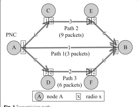
An indoor IEEE 802.15.3c WPAN consisting ofN − 1 wireless nodes (WNs) and a piconet controller (PNC) is considered. As an example, a 6-node WPAN is illus-trated in Fig.1. Each WN and PNC in the network are equipped with electronically steerable directional anten-nas for directional data transmissions by beamforming. The superframe contains three periods. Network synchro-nization and control messages broadcasting from the PNC are processed in the beacon period (BP). The transmis-sion requests of the WNs are sent to the PNC in the contention access period (CAP). The data transmission among WNs in peer-to-peer fashion occurs during the channel time allocation period (CTAP) [3]. The number of timeslots involved in the CTAP during each superframe is adjusted adaptively according to the total occupied time slots. Besides, the system runs a bootstrapping program [1], through which the up-to-date network topology and the location information of other devices are known by each device.
3.2 Transmission model 3.2.1 Antenna model
The directional antenna model proposed in [4] has been widely used, which has a main lobe of Gaussian form and constant level of side lobes. In this model, the direc-tional antenna gain expressed in units of dB is defined asG(α,θ−3dB), where α is the angle between the trans-mission direction (receiving direction) and center line of the transmitter’s (receiver’s) sector beam, θ−3dB is the antenna’s half-power bandwidth (HPBW).
3.2.2 Channel model
In this paper, directional LOS transmission is adopted to achieve high data rate transmission and maximize
Fig. 1Transmission path
the power efficiency [1]. For each directional link li , we denote its transmitter and receiver nodes as ti and ri, respectively. We also denote the distance in meters betweenti andriasdii. For example, we define the link fromAtoBin Fig.1asl2, thent2andr2represent nodeA andB, respectively. The distance between nodeAandBis given byd22. Considering the low user mobility and LOS transmission for indoor WPANs, the path loss at distance diiin dB can be modeled as
L(dii)=ALOS+20 log 10(f)+10ρlog 10(dii), (1)
wheref is the carrier frequency in GHz,ρis the path loss exponent, and ALOS is a constant. The values ofρ and ALOSdepend on the specific scenario [4]. As the average value of the instantaneous path loss possesses low devia-tions, the assumption that no shadowing fading inALOSis reasonable. The received signal power ofriin dB is given by
Pr(i,i)=Pt(ti)+Gti+Gri−L(dii), (2)
wherePt(ti)is the transmit power ofti,Gtiis the transmit
antenna gain ofti, andGriis the receive antenna gain ofri.
Similarly, if linkliandljtransmit with the same frequency simultaneously, the received interference power fromtjto rican be calculated as
Pr(i,j)=Pt(tj)+Gtj+Gri−L
dij
. (3)
3.3 Interference level
For each linkli, we suppose the minimum SINR to support its transmission rateci as MS(ci). Therefore, concurrent transmissions are supported if the SINR of each link li is not smaller than MS(ci)[4]. To guarantee the success-ful transmission of link li, the SINR constraint can be expressed as
Pr(i,i) PN +
j=i
Pr(i,j) ≥
MS(ci), (4)
wherePr(i,j)denotes the interference power from linklj, andljdenotes the link concurrent transmitted with linkli at the same frequency.PN = N0W0is the ambient noise power level, whereW0is the bandwidth andN0is the one-sided power spectra density of white Gaussian noise. (4) can also be written as
MS(Ci)· j=i
Pr(i,j)
Pr(i,i)−MS(Ci)·PN ≤
1. (5)
To facilitate the analysis, interference level is defined to quantize the interference between any two concurrent transmitted links at the same frequency. Then the inter-ference level caused by link lj to li can be defined as
Wi,j=
MS(Ci)·Pr(i,j) Pr(i,i)−MS(Ci)·PN
(5) is satisfied when j=i
Wi,j ≤ 1. Therefore, the SINR
condition of a successful transmission of link li can be summarized as
Ii=
j=i
Wi,j∈[0, 1] , (7)
whereljdenotes the link concurrent transmitted with link li at the same frequency. We define Iias the cumulative interference level of linkli. With the definition of cumula-tive interference level, the SINR condition is converted to a summation form.
For link li, each radio interface of transmitter ti and receiverriis equipped with a directional antenna that can be tuned to a specific direction and channel for data trans-mission. We denote the set of radios of nodeti andrias RtiandRri. We also define the set of channels asC.
Dur-ing the schedulDur-ing, we should specify the radio that node ti employs, the radio that node ri uses, and the channel occupied by linkli. The definition of tuple link is proposed for this purpose. The linklibetweentiandrican be fur-ther defined as a node-radio-channel tuple, i.e., tuple link. The set of tuple links of linkliis defined asLi. According to the method of permutation and combination, the num-ber of tuple links of linkliis given by|Li| =Rti·Rri·|C|. nodeBemploys radio 2, and channel 1 is occupied by the link.
The interference level caused by tuple linklyj tolixcan be defined as
The cases are defined as follows:
• Case 1:lxi does not exist in reality, i.e.,ti=ri.
• Case 2:lxi =lyj, which means thati=j,x=y.lxi and
lyj are the same tuple link.
• Case 3:lxi =ljy, which means thatlxi andlyj are different tuple links. They operate on a diverse channel with disparate radios.
• Case 4:lxi =ljy, they share the same radio.
• Case 5:lxi =ljy, they have the common node(s) and operate on the same channel with disparate radios. The common node(s) transmit and receive simultaneously [15].
• Case 6: Except for the above cases, we obtain the interference levelWi,jwith (6).
3.4 Problem overview
To improve the throughput of the network, the flow with low transmission rate on the direct link will be transmitted through multiple paths to enhance the transmission effi-ciency. The object of the schedule is to clear all the flows within a minimum number of time slots.
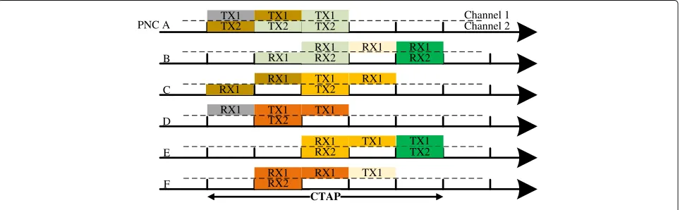
As an example, a 6-node WPAN, i.e.,A,B,C,D,E, and F, is illustrated in Fig. 1 to describe the basic idea of MPMH-MRMC. The numbers in the middle of the direct links indicate the number of packets can be transmitted by these links in one time slot. The flow fromAtoB con-sists of 18 packets. In the MPMH-MRMC, three paths, the path of A → B (path 1), A → C → E → B (path 2), andA → D → F → B(path 3) are selected for the flow fromAtoB. The traffic is proportionally dis-tributed according to the lowest transmission rate on each path [1]. Therefore, three packets, nine packets, and six packets are distributed to paths 1, 2, and 3, respectively. Assuming that each node has two radios and there are two channels, the scheduling result of MPMH-MRMC is illustrated in Fig. 2, where the unit of the scale is time slot. The concurrent transmissions in the same time slots are named pairing in this paper. It is shown that the schedule has 5 pairings, which means that the flow can be scheduled in 5 time slots. In the 4-th pairing, tuple links RA,1,RB,1,C1
transmit concurrently. However, 9 time slots are needed if they are transmitted from A to B directly. From the results, it is known that the efficiency of transmission is improved.
4 Problem formulation
In this section, we convert the problem of optimal MPMH-MRMC scheduling into a standard MILP based on the Reformulation-Linearization Technique (RLT) [21]. We list the notations in Table 1 for better under-standing of the problem formulation.
4.1 Problem formulation and analysis
We assume that there are V flows to be scheduled by the PNC. For flows with low transmission rates or high traffic demands, more time slots are allocated to handle their traffic demands. Since these extra time slots cannot be used in concurrent transmissions, the system per-formance will deteriorate. To improve throughput, they should be transmitted through multiple paths to enhance spatial reuse. The flow transmitted through multiple paths will be selected with the method in [1].
Channel 1
Fig. 2An example of MPMH-MRMC operation applying MILP
demand and the traffic demand distributed to the p-th path asdv anddvp, respectively. The links of a path are sorted by the links’ hop number, i.e., the link of the first hop of thep-th path is denoted as the first link of thep -th pa-th. Thei-th link of thep-th path of thev-th flow is defined aslvpi, and its transmission rate iscvpi. According to the previous definition, there existsLvpituple links between transmitter tvpi and receiver rvpi. Their trans-mission rates are alsocvpi. We assume that there are K pairings in the schedule to handle all the traffics, and the k-th pairing consists one time slot. We also use indica-tor function akvpi, axkvpi to express whether linklvpi, tuple
Table 1Notation in problem formulation
Symbol Description
K The number of pairings in a schedule
V The number of flows in the network
Mv The number of paths of thev-th flow
Hvp The number of hops of thep-th path of thev-th flow
dv The traffic demand of thev-th flow
dvp The traffic demand distributed to thep-th path
lvpi Thei-th link of thep-th path of thev-th flow
cvpi The transmission rate of linklvpi
Luqj The set of tuple links of linklvpi
lx
vpi Thex-th tuple link of linklvpi
tvpi The transmitter of linklvpi(tuple linklxvpi)
rvpi The receiver of linklvpi(tuple linklxvpi)
ak
vpi A binary variable to indicate whether linklvpiis scheduled in thek-th pairing
axkvpi A binary variable to indicate whether tuple linklxvpiis scheduled in thek-th pairing
Rtpi The set of radios of nodetvpi
C The set of channels in the network
Wxvpi,y,uqj The interference level of tuple linklvpix caused bylyuqj
linklxvpi, i.e., thex-th tuple link of linklvpi, is scheduled in thek-th pairing, respectively.akvpi/axkvpiis assigned 1 when lvpi/lxvpiis scheduled. Besides, the interference level caused by tuple linklyuqjtolxvpiis defined asWvpi,uqjx,y .
For example, we assume the flow from nodeAtoBin Fig.1 is the first flow, then we haveM1 = 3,H11 = 1, H12 =3, andH13 = 3. Besides, the traffic demand of the first flow and the traffic demand distributed to the three paths are given byd1=18,d11 =3,d12=9, andd13=6. The link fromAtoBis the first link of the first path of the first flow. It is denoted asl111, and the rate of linkl111is c111. Similarly, the link fromDtoFis given byl132. Then, the transmittert111and receiverr111represent nodeAand B, respectively. The number of tuple links betweenAand Bis|L111|. Besides,a2111anda32111are indicators to express whether linkl111 and tuple linkl3111, i.e., the third tuple link of linkl111are scheduled in the second pairing. The interference level caused by tuple linkl2132tol3111is defined asW111,1323,2 .
An optimal schedule should clear all the flows within a minimum number of time slots, which implies maximum parallelism of transmissions. We formulate the optimal MPMH-MRMC scheduling problem P1 as:
axkvpi∈
This is an MINLP problem, which is generally NP-hard. The explanations of these constraints are as follows:
• Constraint (10) indicates regular flow restriction. • Constraints (11) and (12) indicate that linklvpishould nodestvpi,rvpicould be scheduled in one pairing.
• Constraint (15) indicates that the traffic of linklvpi should be accommodated in the schedule. • Constraints (16)–(18) represent scheduling
restrictions. Constraint (16) indicates the inherent order of transmission in each path, the(i+1)-th link of thep-th path of the v-th flow should be scheduled after thei -th link. Constraints (17)–(18) indicate SINR restriction for concurrent transmissions.
4.2 Problem reformulation
Problem P1 has a nonlinear constraint (18). We apply the RLT to obtain a linear relaxation [21]. Problem P1 will become a standard MILP, which can be solved by some existing sophisticated algorithms, such as the branch-and-bound method.
For constraint (18), we define a substitution variable μx,y,k
1. Then, we can obtain the RLT bound-factor product constraints forμxykvpi,uqjas
⎧
where{·}LSrepresents a linearization step underμx,y,kvpi,uqj=
axkvpiaykuqj. By substitutingμvpi,uqjx,y,k =axkvpiaykuqj, we obtain
Substituting μxykvpi,uqj into constraint (18), we obtain an MILP relaxation P2 as
5 The MPMH-MRMC scheme
To initialize problem P2, the suitable transmission paths should be selected. Besides, the traffic of each flow should be distributed to its selected paths efficiently. The path selection and traffic distribution method proposed in [1] are adopted. In this section, we demonstrate a heuris-tic scheduling algorithm that can solve problem P2 with low computational complexity. The notations are listed in Table2to facilitate the understanding of MPMH-MRMC.
5.1 Symbols in MPMH-MRMC scheme
Assuming that the number of radios of each node in the network is the same, which is denoted asR0. The num-ber of channels|C| is no less thanR0. In a pairing, the SINR of each tuple link should be larger than its threshold. It means that the maximum number of tuple links in the same pairing isR0· N/2. According to the traffic of each path, the number of time slots for a link to accommodate its traffic is set as the weight of this link.
In the transmission scheduling, the set of selected paths of all flows is defined asPs. The set of links inPsis denoted asH. As mentioned in Section4.2, the links of a path are sorted by the links’ hop number. We denote thei-th link of thep-th path ofPsaslpi. Thex-th tuple link of linklpi is given bylxpi. The initial weight of each linklpiis defined aswpi. The remaining weight of linklpi in thet-th pair-ing is defined aswtpi. Thet-th pairing consists of at least
Table 2Notation in MPMH-MRMC
Symbol Description
R0 The number of radios of a node in the network
N The number of nodes
Ps Set of selected paths of all flows
H Set of links inPs
lpi Thei-th link of thep-th path
lx
pi Thex-th tuple link of linklpi wpi The initial weight of linklpi
wt
pi The remaining weight of linklpiin thet-th pairing tpi The transmitter of linklpi(tuple linklxpi)
rpi The receiver of linklpi(tuple linklxpi)
Rttpi Set of unused radios of transmittertpiin thet-th pairing
Rtrpi Set of unused radios of receiverrpiin thet-th pairing
Fp The hop number of the first unscheduled link of thep-th path
Ptmuh Set of unvisited paths with the largest number of unscheduled links
Pt
u Set of unvisited paths in thet-th pairing Ht Set of links in thet-th pairing
Ht0 Set of tuple links in thet-th pairing
δt Number of time slots of thet-th pairing Ixpi The cumulative interference level of tuple linklxpi
one time slot. The transmitter and receiver of linklpi/tuple linklxpiare denoted astpiandrpi, respectively. The sets of unoccupied radios of nodestpiandrpiin thet-th pairing are expressed asRttpiandRtrpi. LetFpdenote the hop num-ber of first unscheduled link of thep-th path. The set of unvisited paths with the largest number of unscheduled hops in thet-th pairing is given byPtmuh. The set of paths that are not visited in thet-th pairing is denoted asPtu. The sets of links and tuple links of thet-th pairing are defined asHtandHt0, respectively. Besides, we denote the number of time slots of thet-th pairing asδt.
For example, the network illustrated in Fig.1has one flow fromAtoB. Then,Pscontains three paths:A → B (first path,p = 1), A → C → E → B(second path, p=2), andA→D→F →B(third path,p=3). Thus, Hconsists of seven links. The first link of the third path is A→D, which is denoted byl31. The initial weight of link l31isw31=1. The remaining weight of linkl31in thet-th pairing is defined aswt31. The transmittert31and receiver t31of linkl31 represent nodesAandB, respectively. Ini-tially, we haveFp = 1,p = 1, 2, 3, which means that the first link of the three paths has not been scheduled. Since path 2 and path 3 both contain 3 links before the sched-ule,P1muhcontains 2 paths: the second and third path. We haveP1muh=pp=2, 3.
5.2 Working mechanism of MPMH-MRMC scheme In the MPMH-MRMC scheme, we define two mecha-nisms, namely, the link selection mechanism and the tuple link schedule mechanism.
Link selection mechanism:Assuming that the set of unvisited paths with the largest number of unscheduled hops in thet-th pairing is denoted byPtmuh. As mentioned in5.1, the hop number of the first unscheduled link of the p-th path is defined asFp. The weight of linklpFp,p∈P
muh will be selected. We have
lpi= min p∈Pt
muh
wtpFp. (23)
Tuple link schedule mechanism:Assuming that link lpiis selected in thet-th pairing. The tuple linklxpi0brings minimum interference to the concurrent transmissions inHt0 will be selected. We denote the cumulative inter-ference level of tuple linklxpi asIpix. Then, the tuple link
IfI0≤1, tuple linklxpi0will be added toHt0and scheduled. Linklpiwill be added toHtaccordingly.
Considering the SINR constraint, the flow chart of the heuristic traffic scheduling algorithm is presented in Fig.3. The algorithm can be described as
Step 1: Select the tuple links to schedule in a pairing. Select linklpi according to the link selection mechanism until Ptu = φ or |Ht| > R0· N/2. The correspond-ing tuple linklxpiis scheduled according to the tuple link schedule mechanism;
Step 2: Schedule the unoccupied radios of selected link lpi in Ht. The corresponding tuple link lxpi is scheduled according to the tuple link schedule mechanism;
Step 3: Determine the number of time slots of the pair-ing. Repeat step 2 until no more tuple links can be added toHt0. The minimum time slots needed for a linklpiinHt to accommodate its traffic isδtpi. The number of time slots
of thet-th pairing isδt= min
The pseudo code of the heuristic traffic scheduling algo-rithm is presented in Algoalgo-rithm 1. Line 4 obtains the suitable linklpi. Firstly, it gets the set of unvisited paths with the largest number of unscheduled hopsPtmuhin the t-th pairing. Then, it gets the link of pathp∈Ptmuh with the minimum weightwtpF
p, which is denoted as lpi. Line
5 selects the tuple linklxpithat brings minimum interfer-ence to the tuple links inHt0. Lines 8–12 utilize the idle radios of the transmitters and receivers of scheduled links inHt when there are remained data to transmit. Line 13 obtains the duration oft-th pairingδt.δtis the minimum time needed for a link in Ht to accommodate its traffic. Lines 14–17 update the weight of each scheduled link and
Fig. 3The flow chart of the transmission scheduling algorithm
delete the linklpiwhen all its traffic has been dealt with. Meanwhile,Fpis renewed.
Algorithm 1The transmission scheduling algorithm Initialization:
The pseudo code of the TLS algorithm is presented in Algorithm 2. It is used for selecting the tuple linklxpithat brings minimum interference to the tuple links in Ht0. Line 1 examines the initial conditions for each selection. The algorithm starts when the transmitter and receiver own idle radios. Line 2 selects the tuple link lxpi with minimum interference to the tuple links in Ht0 accord-ing to the cumulative interference levelIyqj. With different lpix ∈/Ht0, it calculates the cumulative interference level
Iqjy for each tuple link lqjy in Ht0∪
lpix
and obtains the maximum value. Thus, it gets a maximum cumulative interference level set. The tuple linklx0
the smallest value in the maximum cumulative interfer-ence level set will be selected. Line 3 gets the maximum cumulative interference level of links inHt0∪lx0
pi
. Line 4 is a SINR condition to guarantee concurrent transmis-sions. Lines 6–8 renewHt,Ht0,wtpi,Rttpi, andRtrpionce the SINR condition is met.
Algorithm 2The tuple link selection (TLS) algorithm Initialization:
5: Obtain the occupied radios oftpiandrpi, which are denoted byRtpi,z1andRrpi,z2, respectively;
As mentioned in4.3, the interference level between tuple linklxpi andlqjy, i.e.,Wpi,qjx,y , of case 6 is assumed to be 0.1 in Fig.1. Applying this algorithm to the example in Fig.1, it needs nine and five time slots in SRSC and MRMC (2-radio 2-channel) situation, respectively. The schedul-ing process in 2-radio 2-channel situation is illustrated in Fig.4. The algorithm process is as follows:
Step 1: Initially, paths 2 and 3 both have three hops unscheduled, we haveFp = 1,p = 1, 2, 3, and P1muh =
pp=2, 3. According to the number of packets and rate of each link, we havew12,1 = 2 and w13,1 = 1. As δ1 = 0, linkl
31will be selected based on the criterion of line 4 in Algorithm 1. SinceH10=φ, each tuple link of link l31is suitable to be added toH10according to Algorithm 2. We choose the one with minimum subscript of radios and channel, which is denoted asRA,1,RD,1,C1. At the same ever, according to algorithm 2, linkl11 will not be added toH1since the radios of transmittert11 (nodeA) are all occupied. The while loop between lines 3 and 7 will stop asPtu=0.
Step 2:No tuple links will be added to H10 during the while loop between lines 8 and 11 since nodeAhas no free radios.
Step 3:We obtain the renewedδ1,w2,1, andw3,1, which are give byδ1=1,w2,1=1, andw3,1=0.
Step 4:l3,1will be removed fromH.F3will increase by 1 since all the traffic ofl3,1has been cleared, which is given byF3= 2. The process of the second to fifth pairings are similar to the first pairing.
The scheduling results of our algorithm in SRSC sit-uation are as follows: in the first pairing, link A → D transmits for one time slot; in the second pairing, links A → CandD → F transmit for two time slots; in the third pairing, linksD → F,C → E, andA → B trans-mit for one time slot; in the fourth pairing, linksC → E andA → Btransmit for two time slots; in the fifth pair-ing, linkE → Btransmits for two time slots; in the sixth pairing, linkF → Btransmits for one time slot. How-ever, it consumes 10 time slots with the algorithm in [1] in
Channel 1
the SRSC situation. As analyzed in Section4.3, the opti-mal solution takes nine and five time slots. Therefore, our heuristic scheme obtains results close to the optimal solution.
The path selection algorithm has the computational complexity of ONHmax, where Hmax is the maximum number of hops for each selected path [1]. The compu-tational complexity of the traffic distribution algorithm is negligible [1]. The transmission scheduling algorithm has the complexity ofON2. Thus, the total complexity of the scheme is ONHmax+N2, which is pseudo-polynomial. Thus, our scheme is practical for WPANs.
With the introduction of MPMH-MRMC, the con-trol overhead will be increased since more schedul-ing information needs to be broadcasted to the nodes in the WPAN. Based on the directional MAC struc-ture in Section3.1, network synchronization and control messages for the (m −1)-th transmission requests are broadcasted in the m-th BP from the PNC. During the m-th CAP period, the PNC receives several transmission requests [3]. As mentioned in [1,2], the BP or CAP can be completed by the PNC in one time slot. The PNC makes the path selection and scheduling decision for the(m+1) -th CTAP during -the m-th CTAP. One CTAP contains nearly 1000 time slots. Generally, only a few time slots are needed for the PNC to complete path selection and sched-ule computation [1]. Considering that one frame consists of 1000 time slots [1,3] and the Gbps transmission rates of the mmWave communications, the increase of the control overhead can be neglected.
6 Simulation results
In this section, we evaluate the performance of the pro-posed algorithm with respect to average delay and net-work throughput under two different traffic patterns. The algorithm applied in SRSC and MRMC situation are named MPMH-SRSC and MPMH-MRMC, respec-tively. We compare MPMH-SRSC and MPMH-MRMC with MPMH [1], MPMH2, and TDMA schemes. MPMH2 scheme applies the MPMH scheme [1] in MRMC situa-tion by utilizing the TLS algorithm proposed in our paper. TDMA scheme supports only one active transmission in each time slot. In the MRMC situation, each node con-tains four radios, and there are four orthogonal channels in the network.
6.1 Simulation setup
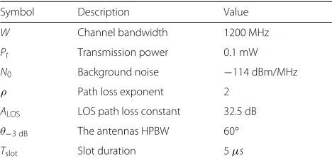
In the simulation, a typical mmWave WPAN with 10 nodes is considered. It is assumed that all nodes are uni-formly distributed in an area of 9×9m2. Considering link lpi, the angle between the transmitting (receiving) direc-tion and the center line of the beam of transmitter tpi (receiverrpi) is assumed as 0◦. Four transmission rates 2, 4, 6, and 8 Gbps are set based on the distance between WNs.
A typical physical layer parameter setting of mmWave WPANs is shown in Table 3. There are 10 flows in the network. The path selection and traffic distribution are obtained with the method in [1], and the maximum num-ber of hopsHmaxfor each selected path is set to 3. We set the size of data packets to 1000 bytes. With the 2 Gbps transmission rate, a packet can be transmitted in a time slot [2]. The length of simulation is set to 5×10⁴time slots. A frame consists of 1000 time slots. The delay threshold is 2.5×10⁴time slots, and packets with delay larger than the threshold will be discarded. The traffic mode is assumed to be Poisson process.
Poisson process:packets of each flow are generated fol-lowing a Poisson process with arrival rateλi. The traffic load ratio given byTlcan be defined as
Tl=
L· V
i=1 λi
/R, (26)
whereLis the size of data packets in bit,Vis the number of flows, andRis set to be 2 Gbps.
In the simulation, two traffic patterns are adopted. 1) Uniform traffic:All flows have the same arrival rate λ, i.e.,λi=λ, which is adopted in [1].
2) Random traffic: The arrival rate of flow i, λi, is randomly generated.
The system performance is evaluated by the following two metrics:
1) Average delay:The average delay of received packets of all flows, and the unit is time slot. The delay caused by BP and CAP is not calculated.
2) Network throughput: The number of successfully transmitted packets of all flows during the entire simula-tion, and the unit is packet. A packet will be counted as a successfully transmitted packet when its delay is no more than the threshold.
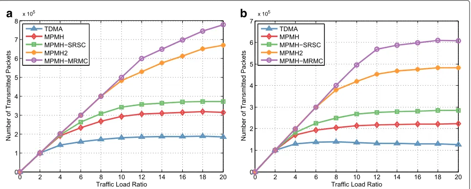
6.2 Network throughput with different traffic load ratio We evaluate the network throughput of five protocols with different traffic load ratio in Fig. 5. It can be observed that MPMH-SRSC outperforms MPMH and TDMA in all cases, and the gap between MPMH-SRSC
Table 3Simulation parameters
Symbol Description Value
W Channel bandwidth 1200 MHz
Pt Transmission power 0.1 mW
N0 Background noise −114 dBm/MHz
ρ Path loss exponent 2
ALOS LOS path loss constant 32.5 dB
θ−3 dB The antennas HPBW 60◦
a
b
Fig. 5Network throughput of the five MAC protocols under different traffic load ratios.aUniform traffic.bRandom traffic
and MPMH is more significant under heavy load. Under light load, the delay is small, and all the arrived packets can be transmitted successfully when applying MPMH-SRSC and MPMH. Thus, the throughput of MPMH-SRSC and MPMH increase linearly under light load. Compared with MPMH, MPMH-SRSC increases the network through-put with the traffic load ratio from 10 to 20 on average by about 17.09% under uniform traffic and 27.09% under random traffic, respectively.
The increment of the random traffic is larger than that of the uniform traffic. The reasons are as follows. Under uniform traffic, the transmission durations of links in a pairing are diverse in MPMH [1]. The diversities bring about the waste of time slots in a pairing. The differences among the transmission durations of links in a pairing under random traffic are worse, which result in further degradations in the throughput performance. However, the transmission durations of links in a pairing are the same under both traffic patterns in MPMH-SRSC. Thus, it outperforms the MPMH under uniform traffic and has greater performance increment under random traffic.
With the introduction of MRMC, MPMH-MRMC can better utilize MPMH than the MPMH-SRSC, and the throughput of MPMH-MRMC increases linearly even under heavy traffic load. With the traffic load ratio from 10 to 20, MPMH-MRMC surpasses MPMH-SRSC by about 82.34% under uniform traffic and 108.29% under random traffic, respectively. Compared with MPMH2, MPMH-MRMC increases the network throughput by about 14.09% under uniform traffic and 25.8% under ran-dom traffic on average with the traffic load ratio from 12 to 20. The reason is the same with the one in SRSC situa-tion. When the traffic load ratio is over 3, the number of
discarded packets in TDMA exceeds MPMH and MPMH-SRSC, which results in smaller network throughput in TDMA. Since the delay threshold is larger than the frame length, the packets that cannot be scheduled in current frame will be transmitted in the next frame. With the increase of the traffic load ratio, the number of packets successful transmitted in the system becomes stable and the network throughput curves become flat.
6.3 Network throughput with different number of flows with multi-path
Under random traffic, the network throughput achieved by the four protocols with different number of flows with multi-path is plotted in Fig. 6. The flows transmitted through MPMH are selected according to traffic demand intensity in [1]. With the same mean traffic load ratio of a flow, the throughput of MPMH-MRMC increases at most about 1.39% when traffic load ratio is 25 with 10 flows and 44.76% when the traffic load ratio is 10 with 4 flows.
a
b
Fig. 6Network throughput of the four MAC protocols under a different number of flows with multi-path.aTraffic load ratio is 25 with 10 flows. bTraffic load ratio is 10 with 4 flows
transmitted through MPMH in both situations. For the similar reason, the performance of MPMH2 decreases when traffic load ratio is 25 with 10 flows and increases about 7.58% when traffic load ratio is 10 with 4 flows.
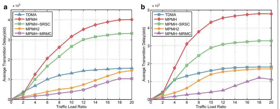
6.4 Average delay with different traffic load ratio
The average delay of five protocols with different traffic load ratio are presented in Fig. 7. We can observe that the delay of the five protocols increases with the increase of traffic load ratio. The arrived packets can be transmit-ted in a short time under light load. Thus, the delay is small in this case. With the traffic load ratio from 3 to 20, compared with MPMH, MPMH-SRSC decreases the
average transmission delay by about 16.53% under uni-form traffic and 32.06% under random traffic on average. The increment of random traffic is larger than uniform traffic. The reason is identical with the one in network throughput.
As mentioned in Section6.2, MPMH-MRMC can bet-ter utilize MPMH than the MPMH-SRSC, which results in the decrease of delay. Compared with MPMH-SRSC, the average transmission delay of MPMH-MRMC decreases by about 74.20% under uniform traffic and 70.91% under random traffic with the traffic load ratio from 10 to 20. With the traffic load ratio from 10 to 20, MPMH-MRMC outperforms MPMH2 by about 29.21% under
a
b
a
b
Fig. 8Average transmission delay of the four MAC protocols under a different number of flows with multi-path.aTraffic load ratio is 25 with 10 flows.bTraffic load ratio is 10 with 4 flows
uniform traffic and 49.04% under random traffic on aver-age, respectively. The reason is identical with the one in network throughput. When the traffic load ratio is over 3, the number of discarded packets in TDMA exceeds MPMH and MPMH-SRSC, which leads to lower average delay in TDMA.
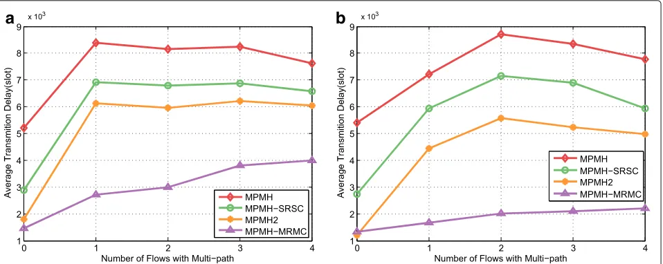
6.5 Average delay with different number of flows with multi-path
In Fig.8, we plot the average delay achieved by the four protocols with different number of flows with multi-path under random traffic. We can observe that the average delay increases when the flow with multi-path is intro-duced, and it decreases a little when more flows are applied with multi-path. As mentioned in Section6.3, one node has fully exploited its radio even when the SRSC is applied in MPMH-SRSC and MPMH. Identical with the reason in network throughput, the performance of average delay degrades when multi-path is introduced. However, the throughput decreases continuously with the increase of numbers of the flows with multi-path, which results in the little decrease of the average delay. The rea-son above can also be used to explain the performance of average delay of MPMH2.
Compared with MPMH, MPMH-SRSC decreases the delay by about 21.86% when the traffic load ratio is 25 with 10 flows and 25.01% when traffic load ratio is 10 with 4 flows, respectively. MRMC surpasses MPMH-SRSC by about 49.96 and 66.72% correspondingly. Besides, MPMH-MRMC outperforms MPMH2 by about 39.33 and 49.04%. The results are consistent with the ones of the network throughput.
7 Conclusions
In this paper, we have proposed a scheduling algo-rithm for mmWave WPANs, which boosts the potential of spatial reuse by concurrent transmissions schedul-ing through MPMH-MRMC. It can sufficiently improve the performance of network throughput and average delay. The proposed heuristic algorithm can achieve the results close to the optimal solution with the complexity ofONHmax+N2. Compared with MPMH, MPMH-SRSC enhances the performance of network throughput and delay by about 22.09 and 24.30% on average, respectively. MPMH-MRMC outperforms MPMH-SRSC in terms of the network throughput and delay by about 95.32 and 72.56% on average. Perfor-mance under different number of flows transmitted through MPMH indicates the number of flows transmit-ted through MPMH should be selectransmit-ted according to the flow density to optimize network performance.
Funding
This work was sponsored by the National Natural Science Foundation of China (61631003).
Availability of data and materials Not applicable.
Authors’ contributions
All authors contribute to the concept, the design and developments of the theory analysis and heuristic algorithm, and the simulation results in this manuscript. All authors read and approved the final manuscript.
Competing interests
The authors declare that they have no competing interests.
Publisher’s Note
Author details
1Key Lab. of Universal Wireless Communications Ministry of Education, Beijing
University of Posts and Telecommunications (BUPT), Haidian Dist. Xitucheng Rd., Beijing, People’s Republic of China.2China Academy of Information and Communications Technology, No.52, Huayuanbei Rd., Haidian Dist., Beijing, People’s Republic of China.
Received: 2 May 2017 Accepted: 7 March 2018
References
1. Y Niu, C Gao, Y Li, D Jin, L Su, D Wu, Boosting spatial reuse via
multiple-path multihop scheduling for directional mmWave WPANs. IEEE Trans. Veh. Technol.65(8), 6614–6627 (2016)
2. IK Son, S Mao, MX Gong, Y Li, inProc. IEEE International Conference on Computer Communications (INFOCOM). On frame-based scheduling for directional mmWave WPANs, (2012), pp. 2149–2157
3. J Qiao, LX Cai, X Shen, JW Mark, inProc. IEEE International Conference on Communications (ICC). STDMA-based scheduling algorithm for concurrent transmissions in directional millimeter Wave Networks, (2012), pp. 5221–5225
4. Z Yan, B Li, X Zuo, M Yang, inProc. IEEE Wireless Communications and Networking Conference (WCNC). A Heuristic clique based STDMA scheduling algorithm for spatial concurrent transmission in mmWave networks, (2015), pp. 1036–1041
5. J Qiao, LX Cai, X Shen, JW Mark, Enabling multi-hop concurrent transmissions in 60 GHz wireless personal area networks. IEEE Trans. Wireless Commun.10(11), 3824–3833 (2011)
6. MX Cheng, Q Ye, L Cai, Rate-adaptive concurrent transmission scheduling schemes for WPANs with directional antennas. IEEE Trans. Veh. Technol. 64(9), 4113–4123 (2015)
7. P Xu, H Chu, inProc. IEEE Wireless Communications and Networking Conference (WCNC). A novel link scheduling strategy for concurrent transmission in mmWave WPANs based on beamforming information, (2014), pp. 1709–1714
8. L Zhou, X Cao, L Liu, L Cai, inProc. IEEE International Conference on Communications (ICC). On capacity optimization in multi-radio multi-channel wireless networks with directional antennas, (2015), pp. 3745–3750
9. R Mudumbai, S Singh, U Madhow, inProc. IEEE International Conference on Computer Communications (INFOCOM). Medium access control for 60 GHz outdoor mesh networks with highly directional links, (2009),
pp. 2871–2875
10. C-S Sum, Z Lan, R Funada, J Wang, T Baykas, M Rahman, H Harada, Virtual time-slot allocation scheme for throughput enhancement in a millimeter-wave multi-Gbps WPAN system. IEEE J. Sel. Areas Commun. 27(8), 1379–1389 (2009)
11. CS Sum, Z Lan, MA Rahman, J Wang, T Baykas, R Funada, H Harada, S Kato, inProc. IEEE Global Telecommunications Conference (GLOBECOM). A multi-Gbps millimeter-wave WPAN system based on STDMA with heuristic scheduling, (2009), pp. 1–6
12. LX Cai, L Cai, X Shen, JW Mark, REX: a randomized exclusive region based scheduling scheme for mmWave WPANs withdirectional antenna. IEEE Trans. Wirel. Commun.9(1), 113–121 (2010)
13. X An, R Hekmat, inIEEE Vehicular Technology Conference (VTC). Directional MAC protocol for millimeter wave based wireless personal area networks, (2008), pp. 1636–1640
14. CW Pyo, F Kojima, J Wang, H Harada, S Kato, MAC Enhancement for high speed communications in the 802.15.3c mmWave WPAN. Wireless Pers. Commun.51(4), 825–841 (2009)
15. P Dutta, V Mhatre, D Panigrahi, R Rastogi, inProc. IEEE International Conference on Computer Communications (INFOCOM). Joint routing and scheduling in multi-hop wireless networks with directional antennas, (2010), pp. 1–5
16. M Kim, Y Kim, W Lee, Resource allocation scheme for millimeter wave-based WPANs using directional antennas. ETRI J.36(3), 385–395 (2014)
17. M Kim, SE Hong, Y Kim, J Kim, Analysis of resource assignment for directional multihop communications in mm-Wave WPANs. ETRI J.35(1), 120–130 (2013)
18. H Shokri-Ghadikolaei, L Gkatzikis, C Fischione, inProc. IEEE International Conference on Communications (ICC). Beam-searching and transmission scheduling in millimeter wave communications, (2015), pp. 9–14 19. H Su, X Zhang, inProc. Global Telecommunications Conference
(GLOBECOM). Joint link scheduling and routing for directional-antenna based 60 GHz wireless mesh networks, (2009), pp. 1–6
20. M Bilal, M Kang, SC Shah, S-G Kang, Time-slotted scheduling schemes for multi-hop concurrent Transmission in WPANs with directional antenna. ETRI J.36(3), 374–384 (2014)