CERN Tape Archive — from development to production
deployment
Michael C. Davis, Vladímir Bahyl, Germán Cancio, Eric Cano, Julien Leduc, and Steven Murray1,∗
1CERN—European Organization for Nuclear Research, 1211 Geneva 23, Switzerland
Abstract.The first production version of the CERN Tape Archive (CTA) soft-ware is planned to be released during 2019. CTA is designed to replace CAS-TOR as the CERN tape archive solution, to face the scalability and performance challenges arriving with LHC Run–3.
In this paper, we describe the main commonalities and differences between CTA and CASTOR. We outline the functional enhancements and integration steps required to add the CTA tape back-end to an EOS disk storage system. We present and discuss the different deployment and migration scenarios for replacing the five CASTOR instances at CERN, including a description of how the File Transfer Service (FTS) will interface with EOS and CTA.
1 Introduction
The High Energy Physics experiments at CERN generate a deluge of data which must be efficiently archived for later retrieval and analysis. The CERN Tape Archive (CTA) is the new tape storage system for the custodial copy of the physics data.
CTA is a replacement for and evolution from its predecessor, CASTOR [1]. While CAS-TOR provides tape storage, a disk cache and staging functionality, CTA has a more simple design philosophy. CTA is implemented as the tape back-end to the EOS disk system [2], and all disk cache functions are delegated to EOS. As EOS is already thede factostorage system for physics analysis at CERN, CTA aims to provide the “best of both worlds”—EOS disk and CASTOR tape.
The main goal of CTA is to make more efficient use of the tape drives, to handle the higher data rates anticipated during Run–3 and Run–4 of the Large Hadron Collider (LHC). In our previous paper [3], we described how this was to be achieved, by introducing a pre-emptive drive scheduler which can keep tape drives running at full speed all of the time.
1.1 Changing Use Cases for Archival Storage
CERN is facing two main challenges for archival storage over the next decade. First, the rate of data taking and the total volume of data will increase exponentially due to improvements in the luminosity and availability of the LHC and upgrades to the detectors and data acquisition system. Second, constraints in available computing power and disk capacity will change the way in which archival storage is used by the experiments.
∗e-mail: {michael.davis,vladimir.bahyl,german.cancio.melia,eric.cano,julien.leduc,steven.murray}@cern.ch
1.3 EB
2018 2019 2020 2021 2022 2023 2024 2025 2026 202720282029 2030
3.1 EB
0.5 EB
0.25 EB
4.3 EB
2031
Figure 1. Predicted Tape Archival Storage Needs for CERN Tier–0 (evolution of total integrated data on tape per year)
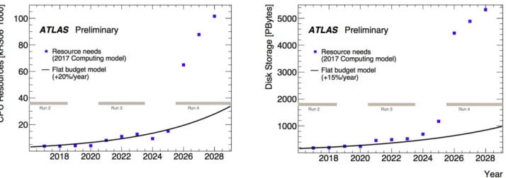
Figure 2.Predicted Compute and Storage Needs against Flat Budget Model for ATLAS
By mid-2018, the total integrated luminosity delivered by the LHC during Run–2 ex-ceeded 150 fb−1, more than double the design luminosity [4]. Run–3 is expected to be simi-lar. After the HL-LHC upgrades, CERN anticipates that the LHC will operate at 5–7×design luminosity, with a predicated total integrated luminosity of 3 000 fb−1during Run–4. Con-sequently, data archival is expected to reach 150 Pb/year during Run–3, increasing to 400 Pb/year during Run–4. The integrated total data on tape will exceed one Exabyte around 2023 (Fig.1).
Increased data rates will also change the way in which archival storage is used. Fig.2 shows that the anticipated compute and storage needs for the experiments will sharply diverge from the budgets during LS–3 and Run–4 [5]. The shortfall in computational resources means that it will no longer be possible to do complete (or comprehensive) data reconstruction, while the shortfall in disk storage means that it will not be possible to keep all of the data online for reconstruction and analysis.
In response to these constraints, the LHC experiments are proposing to make much heav-ier use of tape, as it is a much more economical form of storage than disk. A recent study [6] shows that disk-based storage solutions are about six times as costly as tape library-based solutions on a Total Cost of Ownership per TB basis. The cost savings from increased use of tape will allow the experiments to close the gap between resource needs and the budget.
from CASTOR to CTA during LS2 in time for full operations to resume at the beginning of Run–3.
This paper is organised as follows: Sect.2describes the evolution of CERN’s tape storage system from CASTOR to CTA. Sect.3describes the integration of CTA with EOS and the File Transfer Service (FTS). Sect.4details the setup and results of our scale and stress testing. Sect.5outlines the plans for CTA deployment and migration during LS–2. We summarise in Sect.6.
2 CASTOR to CTA
After the startup of the LHC, physics analysis payloads moved from CASTOR to EOS, which provides low-latency disk-only storage [8]. CASTOR remained as the tape storage system at CERN, with tape archival transfers and recalls staged in and out of CASTOR’s disk system.
To avoid the overhead of maintaining two disk systems, CASTOR disk is replaced by EOS in the new system. CTA has inherited the CASTOR tape server [9], which has been adapted to use CTA’s new control path and metadata. As the CTA system is no longer bound to CASTOR’s internal interfaces, this created an opportunity to redesign the queueing and scheduling features and the tape catalogue, as described below.
2.1 Queueing and Object Store
The control of CTA is based on a queueing system for data movement requests. The queues and requests are stored as objects in a key-value store. For full-scale deployment, the object store backend is Ceph RADOS. A simpler filesystem-based implementation is used for unit tests.
The agents of the system—tape servers and front ends—collaboratively update this shared storage. The update procedure is designed so that a process crash will not cause data corrup-tion or loss. Several maintenance process instances handle failures, e.g. re-queueing the requests that a tape server was working on before it crashed. These maintenance processes free the tape server process from the need to communicate with EOS. They also handle repack requests.
2.2 Tape File Catalogue
The tape file catalogue stores tape file metadata (the physical location of files on tape) and the list of tapes and tape pools. This catalogue, based on a database, is directly accessed by all agents and collaboratively updated. Care has been taken to have a simple table layout, not bound to any specific database implementation, to keep dependencies to a minimum. Full scale deployment is supported on Oracle. An SQLite-based implementation is used for unit tests.
2.3 New Scheduling Features
2.4 New Tape Server Features
The CTA tape server handles unavailable disk files more efficiently than CASTOR because it does not unmount the tape it is writing to when it encounters a disk file problem. The CASTOR tape server unmounts the tape when it cannot read a file from disk. This is costly in terms of time and also causes tape hardware to prematurely wear out.
We are investigating how to add read order optimisation to LTO drives, to compensate for the lack of Recommended Access Order (RAO) [10], which is only available on enterprise drives.
3 EOS, CTA and FTS Integration
3.1 EOS/CTA InstancesAs mentioned in Sect. 2, one of the main goals of CTA to is to delegate disk cache and staging functions to EOS. CTA will add tape storage to a collection of relatively small EOS instances (“EOS/CTA instances”), which are dedicated to staging files to and from tape. As with CASTOR, each LHC experiment will have a dedicated EOS disk staging area. These EOS instances will communicate with a central CTA instance which manages the shared tape resources at CERN.
The ALICE, ATLAS and CMS experiments each have a large disk-only EOS instance which is used to cache data between the experiment data acquisition system (DAQ), the com-pute/batch nodes of reconstruction and analysis, and the the Tier–1 sites of the LHC Grid. The EOS/CTA instance of each experiment will sit behind the large disk-only EOS instance. Ideally, all data in and out of the EOS/CTA instance will pass through the large disk-only EOS instance. This allows us to optimise the size of the disk pool for the EOS/CTA instance. Staging tape files on the EOS/CTA instance and directly transferring them to the Tier–1 sites is therefore discouraged, but the data paths will be tailored to meet the individual needs of each experiment.
3.2 Storage Resource Managers (SRM) and the File Transfer Service (FTS)
The use of tape-enabled Storage Resource Managers (SRM) [11] will be deprecated at CERN and will therefore not be supported by the EOS/CTA instances. Experiments will be able to use the File Transfer Service (FTS) [12] and/or the Grid File Access Library (GFAL2) [13] to transfer their files in and out of their EOS/CTA instance. As the IT Storage Group maintains both FTS and GFAL2, we can tailor solutions to enable the removal of tape-enabled SRM at CERN Tier–0. For transfers between Tier–0 and Tier–1s, FTS supports transfers to and from both SRM-less and SRM-enabled endpoints.
3.3 Data Archiving to Tape
To illustrate how an experiment can work with their EOS/CTA instance, here is the anticipated sequence of events to transfer a raw data file from the DAQ of an experiment to tape:
1. The experiment uses XRootD to copy the raw data file from the DAQ to the large disk-only EOS instance.
it does not unmount the tape it is writing to when it encounters a disk file problem. The CASTOR tape server unmounts the tape when it cannot read a file from disk. This is costly in terms of time and also causes tape hardware to prematurely wear out.
We are investigating how to add read order optimisation to LTO drives, to compensate for the lack of Recommended Access Order (RAO) [10], which is only available on enterprise drives.
3 EOS, CTA and FTS Integration
3.1 EOS/CTA InstancesAs mentioned in Sect. 2, one of the main goals of CTA to is to delegate disk cache and staging functions to EOS. CTA will add tape storage to a collection of relatively small EOS instances (“EOS/CTA instances”), which are dedicated to staging files to and from tape. As with CASTOR, each LHC experiment will have a dedicated EOS disk staging area. These EOS instances will communicate with a central CTA instance which manages the shared tape resources at CERN.
The ALICE, ATLAS and CMS experiments each have a large disk-only EOS instance which is used to cache data between the experiment data acquisition system (DAQ), the com-pute/batch nodes of reconstruction and analysis, and the the Tier–1 sites of the LHC Grid. The EOS/CTA instance of each experiment will sit behind the large disk-only EOS instance. Ideally, all data in and out of the EOS/CTA instance will pass through the large disk-only EOS instance. This allows us to optimise the size of the disk pool for the EOS/CTA instance. Staging tape files on the EOS/CTA instance and directly transferring them to the Tier–1 sites is therefore discouraged, but the data paths will be tailored to meet the individual needs of each experiment.
3.2 Storage Resource Managers (SRM) and the File Transfer Service (FTS)
The use of tape-enabled Storage Resource Managers (SRM) [11] will be deprecated at CERN and will therefore not be supported by the EOS/CTA instances. Experiments will be able to use the File Transfer Service (FTS) [12] and/or the Grid File Access Library (GFAL2) [13] to transfer their files in and out of their EOS/CTA instance. As the IT Storage Group maintains both FTS and GFAL2, we can tailor solutions to enable the removal of tape-enabled SRM at CERN Tier–0. For transfers between Tier–0 and Tier–1s, FTS supports transfers to and from both SRM-less and SRM-enabled endpoints.
3.3 Data Archiving to Tape
To illustrate how an experiment can work with their EOS/CTA instance, here is the anticipated sequence of events to transfer a raw data file from the DAQ of an experiment to tape:
1. The experiment uses XRootD to copy the raw data file from the DAQ to the large disk-only EOS instance.
2. The experiment issues an FTS request to transfer the file from the large disk-only EOS instance to the EOS/CTA instance, using an XRootD Third Party Copy (TPC) transfer.
4. The EOS/CTA instance immediately deletes its disk replica of the file once the file has been safely copied to tape. The file entry remains in the namespace of the EOS/CTA instance.
5. The experiment polls the EOS/CTA instance until the file has been safely archived to tape.
6. The experiment deletes the file from the DAQ.
7. The experiment eventually deletes the file from the large disk-only EOS instance.
3.4 Data Retrieval from Tape
The anticipated sequence to retrieve a file from tape to the disk-only EOS instance is as follows:
1. The experiment issues a request to FTS to bring online and TPC the file from the EOS/CTA instance to the large EOS disk-only instance.
2. FTS uses the XRootD plugin of GFAL2 to request the EOS/CTA instance to bring online (retrieve) the file from tape.
3. FTS uses the XRootD plugin of GFAL2 to poll the EOS/CTA instance for the progress of the bring online operation.
4. Once the bring online has succeeded, FTS automatically initiates an XRootD TPC between the EOS/CTA instance and the large disk-only EOS instance.
5. The garbage collectors of the EOS/CTA instance eventually delete the disk replica from the EOS/CTA instance.
4 Testing
The EOS/CTA software has been deployed on various hardware infrastructures during 2018 to validate its functionality and performance. This validation process confirmed CTA theo-retical performance in the field and slowly shaped future CTA operations.
The successive setups grew along several dimensions: size, hardware variety and software stack complexity. CTA service deployment tools and performance monitoring evolved along with the specifications of the underlying hardware platform and CTA software development. The first deployment setup was aiming for a minimal hardware infrastructure and oper-ation framework. The goal of this pre-production EOS/CTA instance was to validate CTA’s ability to absorb high file archival-retrieval rates. It consisted of two 1GB/s EOS disk servers, two tape servers, and 20 virtual tape drives, but no physical drives. This was ideal for testing tape metadata operations, as nothing is faster than archiving and retrieving small files on a virtual tape server [14]. This setup could deliver over 1 kHz of raw 1 KB file transfer perfor-mance. CTA was able to archive and retrieve up to 10 million files at a sustained 100 Hz rate (Fig.3a).
20 100 40 60 80 120 140 160 0
2 4 6 8 10 12 14 16 18 20 22 24 26 0
Elapsed Time (hours)
M eta da ta Even t R ate (Hz)
(a)Stage In—10 million files archived in≈27 hours
20 100 40 60 80 120 140 160 0
2 4 6 8 10 0
Elapsed Time (hours)
M eta da ta Even t R ate (Hz)
(b)Stage Out—4m files in≈10h
Figure 3.CTA scale tests and stress tests—performance of metadata operations
0.5 2.5 1.0 1.5 2.0 3.0 3.5 0
2 4 6 8 10 12 14 16 18 20
0
Elapsed Time (hours)
Dat a Rat e (GB/s )
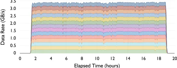
Figure 4. CTA data transfer rates during the Heavy Ion Data Challenge with 14 tape drives (Sept. 2018)
than what we typically see in CASTOR operations (around 10 Hz). The retrieval stress tests demonstrate the same scalability properties of CTA software (Fig.3b).
After this round of artificially heavy metadata performance validation, EOS/CTA was tested with a more realistic experiment workflow. The CTA devops team collaborated with the ATLAS Distributed Data Management (DDM) team to build a significantly more capable testbed: two 10 Gb/s disk servers (raw disk capacity 150 TB), and four 10TKD tape drives (≈ 1 GB/s tape archival throughput, see Fig. 4). This new instance was registered in the ATLAS Grid Information System (AGIS) as a test DDM endpoint and was accessed directly by the ATLAS data transfer tool, Rucio [15]. Rucio submitted approximately 80k files—200 TB of data—for archival through FTS per test session. The EOS/CTA instance sustained an average rate of 1.1 GB/s over more than 48 hours and all files were successfully on tape after 46 hours.
Experiment
(a)CASTOR
Experiment
+ CTA
(b)CTA
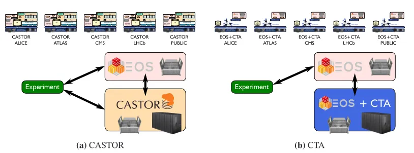
Figure 5.Deployment strategies for CASTOR and CTA
5 Deployment and Migration
There are currently five instances of CASTOR at CERN, one for each of the main LHC ex-periments and a Public instance for everyone else (Fig.5a). CASTOR disk is used for staging files to and from tape, while the associated EOS disk instance is used for reconstruction and analysis (user jobs). When CTA is deployed, each of the CASTOR instances will be replaced by an EOS/CTA instance (Fig.5b). This “small” EOS instance will be optimised for staging files between tape and disk. Staged files will have a short lifetime, and will be evicted from the staging area as soon as they have been safely copied to their final destination.
Due to the increased data rates during Run–3, it is desirable to limit the data transfers to/from the EOS staging area for data stored on tape. Therefore it is envisaged that communi-cation path with the experiments and Tier–1s will pass through the large EOS instance. The small EOS instance will be accessed by privileged experiment accounts and should not be available for user jobs.
5.1 CTA Deployment
During the latter part of 2018, we were in communication with each of the four main LHC ex-periments, to understand their data management practices and to begin to set up test EOS/CTA instances. The metadata and data transfer tests described in Sect.4established that CTA is performant and reliable under workloads in excess of what we expect to see in production during Run–3. The main purpose of testing with the experiments is to ensure that the experi-ment workflows have been properly understood and to ensure that the experiexperi-ments’ use cases have been covered.
ATLAS:The ATLAS EOS/CTA test instance is in place, comprised of one headnode and three disk servers. Data transfers are effected using Rucio as the data management system and FTS as the data mover. The workflow maps well to the large EOS instance for analysis and the small EOS/CTA instance for staging, as ATLAS explicitly do not want a Hierarchical Storage System (HSS); the experiment wants to remain in full control of where files are stored, on disk or on tape. The IT Storage Group is currently writing a commissioning document with ATLAS.
2018
Run 2
2019
LS2
2020
LS2
Run 3
2021
Migration is a metadata-only operation. No physical movement of data on tape.
DATA TAKING AND RETRIEVAL : CASTOR
CTA FIELD TESTING
DATA TAKING AND RETRIEVAL : CTA Migration during period
of reduced data taking.
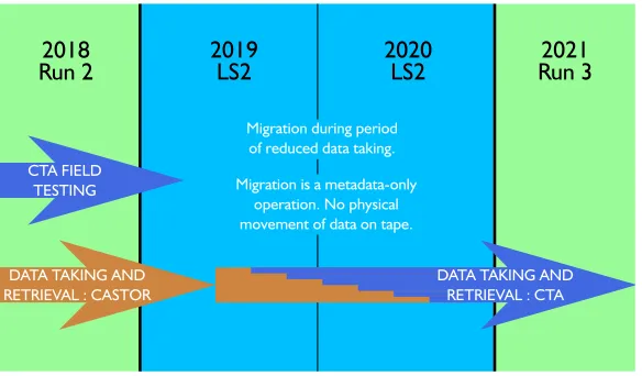
Figure 6.CASTOR to CTA Migration Schedule
CMS:CMS rely on SRM via PheDex, but PheDex is being deprecated in favour of Rucio, so it is anticipated that the CMS deployment solution will follow that of ATLAS.
ALICE:Important preliminary work has been done, to move CASTOR operations “be-hind” the large EOS instance, to separate tape operations from analysis and reconstruction work. Deployment discussions are underway.
PUBLIC:CASTOR Public covers a long tail of small experiments with a broad spectrum of use cases. While the archival needs of these experiments require only a small fraction of tape resources and operational overhead, a significant amount of analysis and preparation will have to be done prior to migration. This work will commence once the four main LHC experiment instance migrations are underway (see Sect.5.2).
5.2 Migration from CASTOR to CTA
Once a production instance of EOS/CTA is in place for each experiment, the files will be migrated from CASTOR to CTA. The format of files on tape is exactly the same in CASTOR and CTA, so no physical movement of data will take place. Migration is a metadata-only operation; the metadata for each file must be moved from the CASTOR namespace to the CTA namespace and the EOS namespaces.
The schedule for migration is shown in Fig.6. Field testing with the experiments began in 3Q2018 and will continue into 2019. Migration from CASTOR to CTA will take place during the Long Shutdown, when data taking is reduced. The exact schedule will be planned in discussions with each experiment, to minimise downtime. It will be possible to carry out the migration in stages, one tape pool (tape family) at a time. CTA will be in full production with all files migrated by the end of LS–2.
We are investigating the possibility of using an XRootD redirector to further minimise disruption to the experiments. This would allow CASTOR and CTA to operate in parallel during the migration. Requests would be directed to CASTOR for files which have not yet been migrated, and to CTA for those which have.
6 Conclusions
reconstruction.
We have described CTA’sraison d’êtreas delivering the “Best of Both Worlds”—EOS disk and CASTOR tape. The CASTOR tape server has been retained as it is proven to be per-formant and reliable. Using EOS for staging to/from tape avoids the maintenance overhead of two separate disk systems, and frees the project from the internal interfaces of CASTOR. This allowed a complete redesign of the queuing and scheduling system, based on a dis-tributed object store, providing a scalable solution for future archival needs.
During 2018, EOS/CTA was integrated with the File Transfer Service (FTS) and discus-sions were opened with the experiments about deployment strategies. The system has been put through its paces with stringent testing of both metadata and data operations. EOS/CTA test instances for each experiment are being set up to ensure that the experiments’ workflows are understood and handled properly. Finally, we outlined the strategy for migrating the ex-periments from CASTOR to CTA during LS–2, with the goal that CTA will take over as CERN’s operational tape archival system for Run–3.
References
[1] G. Lo Presti, O. Barring, A. Earl, R.M.G. Rioja, S. Ponce, G. Taurelli, D. Waldron, M.C. Dos San-tos,CASTOR: A Distributed Storage Resource Facility for High Performance Data Processing at CERN, in24th IEEE Conference on Mass Storage Systems and Technologies (MSST 2007), 24– 27 September 2007, San Diego, California, USA(IEEE Computer Society, 2007), pp. 275–280, ISBN 0–7695–3025–7,http://doi.ieeecomputersociety.org/10.1109/MSST.2007.7
[2] A.J. Peters, E.A. Sindrilaru, G. Adde, Journal of Physics: Conference Series664, 042042 (2015) [3] S. Murray, V. Bahyl, G. Cancio, E. Cano, V. Kotlyar, D.F. Kruse, J. Leduc, Journal of Physics:
Conference Series898, 062013 (2017)
[4] I. Wingerter-Seez,Highlights from the ATLAS Experiment (LISHEP 2018),https://indico. cern.ch/event/675301/contributions/3104623/(2018)
[5] F. Barreiro, D. Benjamin, T. Childers, K. De, J. Elmsheuser, A. Filipcic, A. Klimen-tov, M. Lassnig, T. Maeno, D. Oleynik et al., The Future of Distributed Computing Sys-tems in ATLAS: Boldly Venturing Beyond Grids,https://indico.cern.ch/event/587955/ contributions/2937395/(2018)
[6] D. Reine, M. Kahn,Continuing the search for the right mix of long-term storage infrastructure—a TCO analysis of disk and tape solutions,http://www.clipper.com/research/TCG2015006. pdf(2015)
[7] X. Zhao,Tape Usage (ADC Technical Coordination Board Meeting),https://indico.cern. ch/event/732181/contributions/3019046/(2018)
[8] X. Espinal, E. Bocchi, B. Chan, A. Fiorot, J. Iven, G.L. Presti, J. Lopez, H. Gonzalez, M. Lamanna, L. Mascetti et al., Journal of Physics: Conference Series898, 062028 (2017) [9] E. Cano, S. Murray, D.F. Kruse, V. Kotlyar, D. Côme, Journal of Physics: Conference Series664,
042007 (2015)
[10] C.G. Moraru, Master’s thesis, University Politehnica of Bucharest, Hungary (2017),https:// cds.cern.ch/record/2282014/files/CERN-THESIS-2017-131.pdf
[11] F. Donno, L. Abadie, P. Badino, J.P. Baud, E. Corso, S.D. Witt, P. Fuhrmann, J. Gu, B. Koblitz, S. Lemaitre et al., Journal of Physics: Conference Series119, 062028 (2008)
[12] M.K.S. A. A. Ayllon, M. Salichos, O. Keeble, Journal of Physics: Conference Series513, 032081 (2014)
[13] Grid File Access Library (GFAL2),https://dmc.web.cern.ch/projects/gfal-2/home
[14] M. Harvey,mhVTL,http://www.mhvtl.com/