c
Owned by the authors, published by EDP Sciences, 2017
CMS detector performance
Silvia Goy López on behalf of the CMS collaboration1,a 1CIEMAT, Madrid, Spain and CERN, Geneva, Switzerland
Abstract.The performance of the CMS detector in Run 2 of the LHC, and in particular, with early 2017 data is presented. Special attention is given to the performance of the recently upgraded detector components.
1 Introduction
The Compact Muon Solenoid (CMS) is one of two general purpose detectors at the LHC. The central feature of the CMS apparatus is a superconducting solenoid of 6 m internal diameter, providing an axial magnetic field of 3.8 T. Within the solenoid volume are a silicon pixel and strip tracker, a lead tungstate crystal electromagnetic calorimeter (ECAL), and a brass and scintillator hadron calorimeter (HCAL), each composed of a barrel and two endcap sections. Muons are measured in gas-ionization detectors embedded in the steel flux-return yoke outside the solenoid. Extensive forward calorimetry complements the coverage provided by the barrel and endcap detectors. The CMS experiment has been designed with a two-level trigger system, the Level-1 Trigger (L1), implemented in custom-designed electronics, and the High Level Trigger (HLT), a streamlined version of the CMS offline reconstruction software running on a computer farm. A more detailed description of the CMS detector, together with a definition of the coordinate system used and the relevant kinematic variables, can be found in Ref [1]. During LHC Run 2, which started in 2015 and will continue through 2018, proton-proton collisions are produced at centre-of-mass energies of 13 TeV with 25 ns bunch spacing. This resulted in nearly 60 fb−1 of integrated luminosity delivered to CMS from 2015 until mid-August
2017, 17 fb−1 of which were delivered during 2017. Peak luminosities reached more than 1.7×
1034cm−2s−1, almost twice the instantaneous luminosity CMS was originally designed for. In order to
cope with this harsh environment changes were planned to the CMS detectors, which were carried out during the long shutdown period (LS1, 2013-2014) and throughout the Run 2 period. In particular, the L1 trigger system was partially upgraded in 2015, being fully in place for the 2016 run, the electronics and part of the photo-detectors of the hadronic calorimeter were upgraded at different stages during Run 2, and the CMS pixel detector was completely replaced in the 2016-2017 Extended Year End Technical Stop (EYETS).
In this paper highlights of the CMS detector performance during Run 2, and in particular during the first months of data taking in 2017 are presented.
2 Tracker: Silicon Pixel and Strips
The CMS Tracker consists of two main detectors: a silicon pixel detector and a silicon strip detector. The original CMS silicon pixel detector had 66 million active elements instrumenting a surface area of about 1 m2. It consisted of three concentric cylindrical barrel layers and four fan-blade disks
closing the barrel, two on each end. The system provided efficient three-hit coverage in the region of pseudorapidity|η|<2.2 and efficient two-hit coverage in the region|η|<2.5.
The performance of the original detector at high instaneous luminosity was limited by dynamic inefficiencies and deadtime caused by limited buffer size and readout bandwidth. In order to overcome this limitation, the pixel detector and electronics were replaced in the 2016-2017 EYETS [2]. The upgraded pixel features one additional disk in the forward part and one additional layer in the barrel region, being the inner-most layer closer to the interaction point (at 2.9 cm radius), and the outer most layer further from it (at 16.0 cm) The new geometry permits four-hit coverage within the tracking volume up to|η|=2.5 The new silicon sensors are 285µm thick, and the pixel size is 100×150µm2. Compared to the original, the upgraded detector has higher rate capabilities, an increased number of channels (128 million) and a reduced material budget. New faster digital read out chips are used, and the new module readout bandwidth is 320 Mbit/s, eight times faster than in the original detector. These new features result in increased tracking efficiency, especially at highη values, reduction of fake rate, and improved impact parameter resolution.
The installation of the new pixel detector started on February 28th 2017, and was completed on March 9th. The connection check out was finished by March 12th, the pixel volume was sealed, and the detector was running cold by March 18th, with CMS ready to close on March 24th. Initial commissioning of the new detector was done with cosmic ray muons. After a coarse timing alignment was performed, an initial space alignment was achieved using cosmics ray data at the order of 50-100µm for barrel and forward modules. The fine time alignment was performed using collision data. The time alignment of barrel layers 1 and 2 (where layer numbering starts from the layer closest to the interaction point) was challenging due to the fact that both layers share a common programmable time delay, but the layer 1 read out chip is faster than the rest. Despite that, an optimal common plateau of efficiency could be established with values close to 99% for all pixels layers and disks at luminosities of 1.6×1034Hz/cm2, as shown in Fig. 1 [3, 4]. Here the efficiency is defined as the probability to
find a cluster in a given silicon sensor that has been traversed by a charged particle, measured using isolated tracks originating from the primary vertex. The track pT is required to be>1 GeV, and the
tracks are required to be reconstructed with a minimum of 11 hits measured in the strip detector. The CMS silicon strip detector has 9.3 million active elements instrumenting a surface area of 198 m2, and consists of three large subsystems. The Tracker Inner Barrel and Disks (TIB/TID) deliver
up to fourr-φ measurements on a trajectory using 320µm thick silicon microstrip sensors, which have their strips oriented parallel to the beam axis in the barrel and oriented radially in the disks. The TIB/TID is enclosed within the Tracker Outer Barrel (TOB) which consists of six barrel layers of 500µm thick microstrip sensors with strip pitches of 183µm in the first four layers and 122µm in the last pair of layers. The Tracker EndCaps (TEC) instrument the region 124<|z|<280 cm and 22.0 <r<113.5 cm. Each TEC is composed of nine disks that are instrumented with up to seven rings of radial-strip silicon detectors. The inner two layers of the TIB and TOB, the inner two rings of the TID and TEC, and the fifth ring of the TEC include a second microstrip detector module that is mounted back-to-back at a stereo angle of 100 mrad to provide a measurement of the orthogonal coordinate. Assuming fully efficient planes and not counting hits in stereo modules, there are from 8 to 14 high precision measurements of track impact points for|η|<2.4.
2 Tracker: Silicon Pixel and Strips
The CMS Tracker consists of two main detectors: a silicon pixel detector and a silicon strip detector. The original CMS silicon pixel detector had 66 million active elements instrumenting a surface area of about 1 m2. It consisted of three concentric cylindrical barrel layers and four fan-blade disks
closing the barrel, two on each end. The system provided efficient three-hit coverage in the region of pseudorapidity|η|<2.2 and efficient two-hit coverage in the region|η|<2.5.
The performance of the original detector at high instaneous luminosity was limited by dynamic inefficiencies and deadtime caused by limited buffer size and readout bandwidth. In order to overcome this limitation, the pixel detector and electronics were replaced in the 2016-2017 EYETS [2]. The upgraded pixel features one additional disk in the forward part and one additional layer in the barrel region, being the inner-most layer closer to the interaction point (at 2.9 cm radius), and the outer most layer further from it (at 16.0 cm) The new geometry permits four-hit coverage within the tracking volume up to|η|=2.5 The new silicon sensors are 285µm thick, and the pixel size is 100×150µm2. Compared to the original, the upgraded detector has higher rate capabilities, an increased number of channels (128 million) and a reduced material budget. New faster digital read out chips are used, and the new module readout bandwidth is 320 Mbit/s, eight times faster than in the original detector. These new features result in increased tracking efficiency, especially at highη values, reduction of fake rate, and improved impact parameter resolution.
The installation of the new pixel detector started on February 28th 2017, and was completed on March 9th. The connection check out was finished by March 12th, the pixel volume was sealed, and the detector was running cold by March 18th, with CMS ready to close on March 24th. Initial commissioning of the new detector was done with cosmic ray muons. After a coarse timing alignment was performed, an initial space alignment was achieved using cosmics ray data at the order of 50-100µm for barrel and forward modules. The fine time alignment was performed using collision data. The time alignment of barrel layers 1 and 2 (where layer numbering starts from the layer closest to the interaction point) was challenging due to the fact that both layers share a common programmable time delay, but the layer 1 read out chip is faster than the rest. Despite that, an optimal common plateau of efficiency could be established with values close to 99% for all pixels layers and disks at luminosities of 1.6×1034Hz/cm2, as shown in Fig. 1 [3, 4]. Here the efficiency is defined as the probability to
find a cluster in a given silicon sensor that has been traversed by a charged particle, measured using isolated tracks originating from the primary vertex. The track pT is required to be>1 GeV, and the
tracks are required to be reconstructed with a minimum of 11 hits measured in the strip detector. The CMS silicon strip detector has 9.3 million active elements instrumenting a surface area of 198 m2, and consists of three large subsystems. The Tracker Inner Barrel and Disks (TIB/TID) deliver
up to fourr-φmeasurements on a trajectory using 320µm thick silicon microstrip sensors, which have their strips oriented parallel to the beam axis in the barrel and oriented radially in the disks. The TIB/TID is enclosed within the Tracker Outer Barrel (TOB) which consists of six barrel layers of 500µm thick microstrip sensors with strip pitches of 183µm in the first four layers and 122µm in the last pair of layers. The Tracker EndCaps (TEC) instrument the region 124<|z|<280 cm and 22.0 <r<113.5 cm. Each TEC is composed of nine disks that are instrumented with up to seven rings of radial-strip silicon detectors. The inner two layers of the TIB and TOB, the inner two rings of the TID and TEC, and the fifth ring of the TEC include a second microstrip detector module that is mounted back-to-back at a stereo angle of 100 mrad to provide a measurement of the orthogonal coordinate. Assuming fully efficient planes and not counting hits in stereo modules, there are from 8 to 14 high precision measurements of track impact points for|η|<2.4.
Early commissioning of the silicon strips detector in 2017 showed good signal to noise ratio and good initial module alignment from the start of data taking.
Figure 1.Pixel hit finding efficiency versus instantaneous luminosity for all layers and disks, as measured with 2017 data [3].
Sophisticated tracking and vertexing software algorithms reconstruct the data provided by the silicon tracker. These have been extensively studied on 2011 data in [5].
Algorithms that identify jets originating from heavy (bottom or charmed) hadrons rely heavily on the reconstruction of charged particle tracks inside those jets. The change of the pixel detector has a major impact on the track reconstruction, affecting for example the measured values of the impact parameter (IP) of reconstructed tracks, and the uncertainty on this value. These are very relevant variables in the identification of heavy flavour jets, and are expected to be sensitive to the geometry and alignment of the tracker detector. Fig. 2 shows the distribution of the IP value for jets with pT
between 50 and 250 GeV, pseudorapidity between -2.5 and 2.5 and which contain a muon. The data taken in early 2017 with the upgraded pixel detector are compared to data taken in 2016 proton-proton collisions with the original one [6]. Despite the higher luminosities the new detector achieves already a similar performance as the original one.
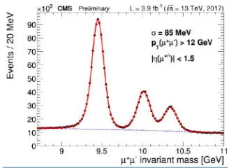
An example of the tracking performance achieved for physics in early 2017 data is shown in Fig. 3, demonstrating excellent mass resolution in the dimuon invariant mass spectra around the Upsilon peaks [7].
3 Electromagnetic Calorimeter
The ECAL is a homogeneous crystal calorimeter made of 75848 lead tungstate (PbWO4) crystals.
These crystals provide fast response, radiation tolerance and excellent energy resolution. The high-density (8.28 g/cm3), short radiation length (X
0=0.89 cm), and small Moli`ere radius (RM=2.2cm) of PbWO4allow the construction of a compact calorimeter with fine granularity, and the fast
scintilla-tion response allows for excellent time resoluscintilla-tion. The detector consists of a barrel region (EB), cov-ering up to pseudorapidity|η|=1.48, and two endcaps (EE), that extend the coverage up to|η|=3.0. Electron and photon identification is possible up to|η| = 2.5 - the region covered by the silicon tracker. The lead tungstate crystals are 25.8X0long in the barrel and 24.7X0long in the endcaps. The
Figure 2. Value of the impact parameter (IP) for the charged particle tracks inside the jets. In black the distri-bution is shown for data taken in 2016 with the original pixel detector. These data are produced with the final optimal ("legacy") reconstruction. In red the distribution is shown for data taken in 2017 with the upgraded pixel detector and after the first prompt reconstruction. The bottom panel shows the ratio of the 2017 divided by the 2016 results. The measured value of the IP shows an asymmetric distribution with a shift towards more positive values. This is expected for a topology that is enriched in heavy flavour jets [6].
Figure 3. Invariant mass distribution of dimuons in the vicinity of the Y(nS) resonances, for an integrated luminosity of 3.9 fb−1of 2017 data at√s=13 TeV [7].
phototriodes (VPTs) in the endcaps. A preshower detector consisting of two planes of silicon strip sensors interleaved with a total of 3X0of lead is located in front of each EE.
While the crystal scintillation mechanism is not altered by irradiation, the crystal transparency is reduced. The VPT response is affected by the total extracted charge, and a signal decrease to a plateau is expected. In order to measure and correct for response changes during LHC operation, the ECAL is equipped with a dedicated light monitoring system. The response change observed in the ECAL channels is up to 10% in the barrel, reaching up to 50% at|η| ≈2.5, the limit of the tracker acceptance. The response change is up to 90% in the region closest to the beam pipe [8]. These measurements are used to recalibrate the ECAL signal amplitudes, both offline and at the trigger level.
Different methods are used to intercalibrate the response of ECAL channels [9]. Theφ-symmetry inter-calibration exploits the invariance around the beam axis of the energy flow in minimum bias events. The invariant mass of photon pairs from low mass resonances (π0 →γγandη→ γγ) is also
used to calibrate the crystal response. Isolated electrons fromW→eνandZ→eedecays are used to compare the energy measured in ECAL to the track momentum measured in the silicon tracker.
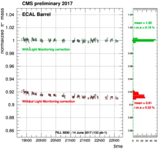
Fig. 4 shows the stability of the relative energy scale measured from the invariant mass distribution ofπ0 → γγdecays in the ECAL Barrel. The energy scale is measured by fitting the invariant mass distribution of approximately 200,000 photon pairs in the mass range of theπ0meson. Each point is obtained from a fit to approximately 8 minutes of data taking. The error bars represent the statistical errors on the fitted peak position. The energy scale is plotted as a function of time, over a period of three hours during an LHC fill.
Figure 4.Stability of the relative energy scale measured from the invariant mass distribution ofπ0→γγdecays
in the ECAL Barrel. The plot shows the data with (green points) and without (red points) light monitoring corrections applied, for data recorded on 14th June 2017 during LHC fill 5830. The right-hand panel shows the projected relative energy scales [8].
The performance of electron and photon reconstruction, identification, isolation and trigger has been measured using the full 2016 data sample [10] showing with good agreement with simulation.
4 Hadronic Calorimeter
The CMS Hadronic calorimeter consists of four sections. The HCAL Barrel (HB) and Endcap (HE) calorimeters cover regions of 0<|η|<1.3 and 1.3<|η|<3, respectively. Both are sampling calorime-ters, made of alternating layers of brass absorber and plastic scintillator tiles, with hybrid photo-detector (HPD) readout. The HCAL Outer (HO) is designed as a tail catcher made of plastic scintilla-tor layers placed outside the CMS solenoid, using the CMS coil as absorber, also with HPD readout. The HCAL Forward (HF) is situated at|z|=11 m covering the range 2.9<|η| <5. It is a Cherenkov calorimeter, with light being collected by scintillating quartz fibres inserted in steel absorber, and read out with photomultipler tubes (PMTs). The stability of the detector response, photo-detector gains and signal time synchronization is monitored using LED and laser systems.
summed to define the calorimeter tower energies, subsequently used to provide the energies and di-rections of hadronic jets. The HCAL, when combined with the ECAL, measures jets with a resolution ∆E/E≈100%/√E[GeV]⊕5% [9].
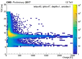
A set of upgrades of the HCAL began during Long Shutdown 1 (LS1, 2013-2014), in order to improve the performance of jet and energy reconstruction in Run 2. During Run 1 electric discharges were observed in the HCAL HPDs, which were particularly relevant in HO due to the presence of the magnetic fringe field. In addition, analysis of LED data showed a time drift of HPD gains. For these reasons all HPDs are planned to be replaced with silicon photomultipliers (SiPM). In particular, the HO detector has already been upgraded with SiPMs during LS1. In the HF, anomalous signals were produced by particles hitting the PMT windows. These PMT have been replaced with thinner window, multi-anode readout design, that mitigates this effect by a significant factor. In addition both HF back-end and front-end electronics have been upgraded in different stages. The front-end electronics includes now high precision timing readout through TDC, and the back-end electronics can handle the increased data bandwidth. Fig. 5 shows the TDC time versus charge in the anode for a given HF channel. Good separation can be observed between particles directly hitting the PMTs sitting at low time values, and hits from standard collision particles [11].
Figure 5.Time as measured by TDC vs anode charge in a given HF channel (ieta=40, iphi=47, depth=1). The contribution with low time values of<5 ns originate from particles directly higgin the PMT. Hits from collision particles populate timing values of around 8 ns [11].
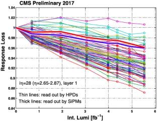
During the 2016-2017 EYETS, a 20 degree phi sector in HE has been upgraded, and the PMTs replaced with SiPMs. Channels read out with SiPMs exhibits smaller signal loss (4% loss after 5.6 /fb of integrated luminosity) compared to channels read out by HPDs ( 7% loss on average), as shown in Fig 6. The response loss in the channels read out by the HPDs is due to two components: damage to HPD photocathodes caused by the charge drawn from them, and radiation damage of scintillators and wavelength shifting fibers. The evident phi non-uniformity observed in HPD channels is understood to be due to HPD deterioration [12].
Further HCAL upgrades are planned after 2017 and after Run 2.
5 Muon System
summed to define the calorimeter tower energies, subsequently used to provide the energies and di-rections of hadronic jets. The HCAL, when combined with the ECAL, measures jets with a resolution ∆E/E≈100%/√E[GeV]⊕5% [9].
A set of upgrades of the HCAL began during Long Shutdown 1 (LS1, 2013-2014), in order to improve the performance of jet and energy reconstruction in Run 2. During Run 1 electric discharges were observed in the HCAL HPDs, which were particularly relevant in HO due to the presence of the magnetic fringe field. In addition, analysis of LED data showed a time drift of HPD gains. For these reasons all HPDs are planned to be replaced with silicon photomultipliers (SiPM). In particular, the HO detector has already been upgraded with SiPMs during LS1. In the HF, anomalous signals were produced by particles hitting the PMT windows. These PMT have been replaced with thinner window, multi-anode readout design, that mitigates this effect by a significant factor. In addition both HF back-end and front-end electronics have been upgraded in different stages. The front-end electronics includes now high precision timing readout through TDC, and the back-end electronics can handle the increased data bandwidth. Fig. 5 shows the TDC time versus charge in the anode for a given HF channel. Good separation can be observed between particles directly hitting the PMTs sitting at low time values, and hits from standard collision particles [11].
Figure 5.Time as measured by TDC vs anode charge in a given HF channel (ieta=40, iphi=47, depth=1). The contribution with low time values of<5 ns originate from particles directly higgin the PMT. Hits from collision particles populate timing values of around 8 ns [11].
During the 2016-2017 EYETS, a 20 degree phi sector in HE has been upgraded, and the PMTs replaced with SiPMs. Channels read out with SiPMs exhibits smaller signal loss (4% loss after 5.6 /fb of integrated luminosity) compared to channels read out by HPDs ( 7% loss on average), as shown in Fig 6. The response loss in the channels read out by the HPDs is due to two components: damage to HPD photocathodes caused by the charge drawn from them, and radiation damage of scintillators and wavelength shifting fibers. The evident phi non-uniformity observed in HPD channels is understood to be due to HPD deterioration [12].
Further HCAL upgrades are planned after 2017 and after Run 2.
5 Muon System
Muon reconstruction in CMS is performed with the all-silicon tracker at the heart of the detector, and with up to four stations of gas-ionization muon detectors installed outside the solenoid and sandwiched between steel layers serving both as hadron absorbers and as a return yoke for the magnetic field. The
Figure 6.Normalized response of HE layer 1 for a phi-ring at high pseudorapidity, as a function of luminosity delivered in 2017, measured with the laser-to-megatile calibration system. Each thin (thick) line represents a channel at a specific phi, read out by an HPD (SiPM) [12].
muon system covers the pseudorapidity region|η|<2.4 and performs three main tasks: triggering on muons, identifying muons, and assisting the CMS tracker in measuring the momentum and charge of high pTmuons.
Drift Tube (DT) chambers and Cathode Strip Chambers (CSC) are used within|η| < 1.2 and 0.9<|η|<2.4 respectively, complemented by a system of Resistive Plate Chambers (RPC) covering the range of|η|<1.6. The basic element of the DT system is the drift cell of 42×13 mm2. The gas
mixture (85%/15% of Ar/CO2) provides good quenching properties and a saturated drift velocity of about 55µm/ns. The maximum drift time is almost 400 ns. A CSC consists of 6 layers, and operates as standard multi-wire proportional counters (MWPC). The cathode strips run radially outward and provide a precise measurement in the r−φbending plane. The wires provide a coarse measurement in the radial direction. All chambers use a gas mixture of 50% CO2, 40% Ar, and 10% CF4. The RPC
are double-gap chambers, operated in avalanche mode to ensure reliable operation at high rates, that can provide fast and independent trigger signals. The spatial resolution per chamber was 80–120µm in the DTs, 40–150µm in the CSCs, and 0.–1.2 cm in the RPCs. The time resolution achievable was 3 ns or better per chamber for all 3 systems. More details on the CMS muon systems and its performance can be found in [13].
During LS1 general repairs and maintenance work have been performed on the three muon sys-tems. The DT readout and trigger electronics have been moved out of the experimental cavern, in order to gain robustness and allow for flexibility in possible future interventions. New CSC and RPC chambers have been installed in the endcap region, resulting in improvements in muon reconstruction and identification and in reduction of muon trigger rate. Part of the CSC electronics has also been upgraded, allowing in particular exploitation of the full chamber segmentation in 2.1<|η| <2.4 and increasing data-rate capacity for Run 2.
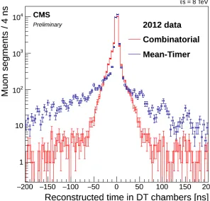
was shown to allow high reconstruction and identification efficiency for Out-Of-Time tracks and to improve the resolution for In-Time-Tracks, as shown in Fig.7.
Figure 7.Comparison between the segment time measurement using the Mean-Timer (in blue) and combinatorial reconstruction (in red) evaluated on the same event sample of 2012 data. Here the time values were derived from single reconstructed segments in single DT chambers [14].
The performance of muon identification and isolation algorithms has been studied using the full 2016 data sample [15]. In general efficiencies are high and good agreement is observed between data and simulation.
6 The Trigger System
The first level of the CMS trigger system uses information from the calorimeters and muon detectors in custom hardware processors to select the most interesting events in a fixed time interval of less than 4µs. The HLT further decreases the event rate by using the full event information, including that from the silicon tracker. During Run 2, 100 kHz of L1 accepted events was reduced to around 1 kHz by the HLT before data storage.
In order to preserve sensitivity for electroweak scale physics and for TeV scale searches similar to that achieved before LS1, CMS has performed major optimizations in the L1 and HLT systems during LS1 and throughout Run 2 [16]. The L1 trigger system underwent major modifications, implemented in a staged approach, allowing for better lepton isolation and pileup subtraction algorithms. New more powerful electronics were put in place, offering much improved flexibility compared to the previous trigger system. The major features of the L1 trigger upgrade were in place for data taking in 2016. Nevertheless, further improvements have been implemented at later stages. Fig. 8 shows the L1 single muon trigger efficiency versus reconstructed muonpTin 2016 and 2017 data for a L1 trigger requiring a 25 GeVpTthreshold. A clear improvement in efficiency can be seen at highpTin 2017 data [17].
The HLT computer farm has also been upgraded, and new algorithms were developed, signifi-cantly reducing tracking time for the Run 2 conditions.
Figure 8.L1 trigger efficiency as a function of reconstructed muonpTfor a muon withpT>25 GeV as measured
at trigger level and passing single muon trigger quality criteria [17].
7 Beam Radiation Instrumentation and Luminosity Measurement
CMS has specific detectors to measure the luminosity and machine induced background. A new data acquisition system and new detectors were put in place for Run 2 in order to provide a continuous real-time measurement of the luminosity delivered by LHC to CMS and in order to measure beam losses, with the main purpose of protecting the silicon pixel and strip tracking detectors by inducing a beam dump if needed.
8 Conclusions
During the LHC Long Shutdown 1 and throughout Run 2, significant upgrades have been imple-mented to the CMS detector in order to stand demanding running conditions beyond initial design expectations. Early 2017 data show that with these upgrades the physics performance of the CMS detector is mantained, and in some aspect improved with respect to the LHC Run 1.
References
[1] CMS Collaboration, The CMS experiment at the CERN LHC, JINST 3 (2008) S08004.
[2] CMS Collaboration, CMS Technical Design Report for the Pixel Detector Upgrade, CERN/LHCC, https://cds.cern.ch/record/1481838.
[3] CMS Collaboration, https://twiki.cern.ch/twiki/bin/view/CMSPublic/PixelOfflinePlotsAugust2017 [4] V. Veszpremi for CMS Collaboration, Performance verification of the CMS Phase-1 Upgrade
Pixel detector, https://arxiv.org/abs/1710.03842, https://cds.cern.ch/record/2287658
[5] CMS Collaboration, Description and performance of track and primary-vertex reconstruction with the CMS tracker J. Instrum. 9 (2014) P10009.
[6] CMS Collaboration, Commissioning studies on the Phase I pixel detector of
CMS in early 2017 proton-proton collisions at 13 TeV, CMS-DP-2017-037 (2017), https://cds.cern.ch/record/2281817.
[8] CMS Collaboration, CMS ECAL Laser monitoring up to 2017,π0/η→ γγspectrum and moni-toring, ES calibration, CMS-DP-2017-023 (2017), https://cds.cern.ch/record/2273269.
[9] CMS Collaboration, Energy calibration and resolution of the CMS electromagnetic calorimeter in pp collisions at √s=7 TeV, J. Instrum. 8 (2013) P09009.
[10] CMS Collaboration, Electron and photon performance in CMS with the full 2016 data sample, CMS-DP-2017-004 (2017), https://cds.cern.ch/record/2255497.
[11] CMS Collaboration, Noise in Phase 1 HF detector in 2017, CMS-DP-2017-034 (2017), https://cds.cern.ch/record/2281147.
[12] CMS Collaboration, HCAL Calibration Status in Summer 2017, CMS-DP-2017-033 (2017), https://cds.cern.ch/record/2281146.
[13] CMS Collaboration, The performance of the CMS muon detector in proton-proton collisions at sqrt(s)=7 TeV at the LHC, JINST 8 (2013) P11002.
[14] CMS Collaboration, Performance of the CMS Muon Detectors in 2016 collision runs, CMS-DP-2016-046 (2016), https://cds.cern.ch/record/2202964.
[15] CMS Collaboration, Muon Identification and Isolation efficiency on full 2016 dataset, CMS-DP-2017-007 (2017), https://cds.cern.ch/record/2257968.
[16] CMS Collaboration, CMS Technical Design Report for the Level-1 Trigger Upgrade, CERN-LHCC-2013-011, https://cds.cern.ch/record/1556311.
![Figure 8. L1 trigger efficiency as a function of reconstructed muon pT for a muon with pT > 25 GeV as measuredat trigger level and passing single muon trigger quality criteria [17].](https://thumb-us.123doks.com/thumbv2/123dok_us/8042469.1339197/9.482.172.307.81.220/figure-trigger-eciency-function-reconstructed-measuredat-passing-criteria.webp)
