Scholarship@Western
Scholarship@Western
Electronic Thesis and Dissertation Repository
11-12-2010 12:00 AM
Collision Detection and Merging of Deformable B-Spline Surfaces
Collision Detection and Merging of Deformable B-Spline Surfaces
in Virtual Reality Environment
in Virtual Reality Environment
Harish PungotraThe Univeristy of Western Ontario
Supervisor Dr. George Knopf
The University of Western Ontario
Graduate Program in Mechanical and Materials Engineering
A thesis submitted in partial fulfillment of the requirements for the degree in Doctor of Philosophy
© Harish Pungotra 2010
Follow this and additional works at: https://ir.lib.uwo.ca/etd
Part of the Computer-Aided Engineering and Design Commons
Recommended Citation Recommended Citation
Pungotra, Harish, "Collision Detection and Merging of Deformable B-Spline Surfaces in Virtual Reality Environment" (2010). Electronic Thesis and Dissertation Repository. 32.
https://ir.lib.uwo.ca/etd/32
This Dissertation/Thesis is brought to you for free and open access by Scholarship@Western. It has been accepted for inclusion in Electronic Thesis and Dissertation Repository by an authorized administrator of
COLLISION DETECTION AND MERGING OF DEFORMABLE B-SPLINE
SURFACES IN VIRTUAL REALITY ENVIRONMENT
Spine title: Collision Detection and Merging of Deformable Surfaces
Thesis Format: Monograph
by
Harish Pungotra
Graduate Program in Mechanical and Materials Engineering
A thesis submitted in partial fulfillment
of the requirements for the degree of
Doctor of Philosophy
The School of Graduate and Postdoctoral Studies
The University of Western Ontario
London, Ontario, Canada
November, 2010
ii
CERTIFICATE OF EXAMINATION
Supervisor
______________________________ Dr. George Knopf
Co-Supervisor
______________________________ Dr. Robert Canas
Supervisory Committee
______________________________
Examiners
______________________________ Dr. Ralph Buchal
_______________________________ Dr. Michael Naish
_______________________________ Dr. Roy Eagleson
_______________________________ Dr. Thenkurussi Kesavadas
The thesis by
Harish Pungotra
entitled:
Collision Detection and Merging of Deformable B-spline Surfaces in
Virtual Reality Environment
is accepted in partial fulfillment of the requirements for the degree of
Doctor of Philosophy
Date___________________ _____________________________
iii
This thesis presents a computational framework for representing, manipulating and merging rigid and deformable freeform objects in virtual reality (VR) environment. The core algorithms for collision detection, merging, and physics-based modeling used within this framework assume that all 3D deformable objects are B-spline surfaces. The interactive design tool can be represented as a B-spline surface, an implicit surface or a
point, to allow the user a variety of rigid or deformable tools. The collision detection
system utilizes the fact that the blending matrices used to discretize the B-spline surface are independent of the position of the control points and, therefore, can be pre-calculated. Complex B-spline surfaces can be generated by merging various B-spline surface patches
using the B-spline surface patches merging algorithm presented in this thesis. Finally, the
physics-based modeling system uses the mass-spring representation to determine the
deformation and the reaction force values provided to the user. This helps to simulate realistic material behaviour of the model and assist the user in validating the design before performing extensive product detailing or finite element analysis using commercially available CAD software. The novelty of the proposed method stems from the pre-calculated blending matrices used to generate the points for graphical rendering, collision detection, merging of B-spline patches, and nodes for the mass spring system. This approach reduces computational time by avoiding the need to solve complex equations for blending functions of B-splines and perform the inversion of large matrices. This alternative approach to the mechanical concept design will also help to do away with the need to build prototypes for conceptualization and preliminary validation of the idea thereby reducing the time and cost of concept design phase and the wastage of resources.
Keywords: collision detection; merging B-spline surfaces; virtual reality; interactive
iv
The completion of this PhD thesis and the work accomplished over the past four years would not have been the possible without the wisdom, help, and support of many whom I do not have enough words to thank.
First and foremost, I would like to thank Prof. George Knopf for giving me the opportunity to be part of his research group, for inspiring and supporting me, and for sharing his research insight and passion with me throughout this long process. I owe him many thanks for his constructive criticism, for his support and encouragement. He has been a source of inspiration in all respects and has provided me a unique prospective to face the challenges in research and life. This thesis is a direct consequence of his endless patience and support.
I would also like to thank Dr. Roberto Canas of the National Research Council of Canada - Institute for Research in Construction (NRC-IRC, London) for his remarkable guidance, encouragement, and constructive criticism throughout my research. I owe him many thanks for helping me during the implementation of algorithms and constantly reminding me to incorporate different scenarios. I am also thankful to researchers and staff of NRC-London. Special thanks to Ms. Percy Gail for editing research papers for grammatical mistakes.
Valuable guidance has been provided by the members of my advisory committee, Prof. Michael D. Naish and Prof. Samuel F. Asokanthan, whose insightful suggestions, criticisms, and encouragements helped me to focus and gave me the motivation to learn and overcome some of the challenges. On the same note, I would like to thank members of my comprehensive examination committee, Prof. Steve Feng and Prof. Jagath Samrabandu for their advice and constructive criticism and for helping me focus on critical aspects of my research.
v Kuldeep.
My sincere gratitude goes to Beant College of Engineering and Technology, Gurdaspur (India) for sanctioning study leave and providing financial assistance during my PhD. I owe many thanks to Dr. Satish Bansal, Dr. Nirmal Singh, Dr. Dial Chand, Mr. Inderpal Singh, Mr. Anil Kumar and Mr. Ashok Kumar for their unwavering support in sanctioning leave and providing timely financial assistance.
I do not have enough words to thank my parents and family for their unconditional love and support over the years. I also feel highly indebted to my brother and sister for their moral and intellectual support and prayers. To my wife Ritu, for always being there for me throughout this journey. To my kids, Anjali and Anuj for their love and understanding. You all have always been there for me. Thank you for everything and for encouraging me to follow my dreams.
Finally, I would like to acknowledge the financial assistance from Faculty of Graduate studies and Natural Sciences and Engineering Research Council of Canada (NSERC).
vi
Au = Blending matrix for the B-spline surface in u direction
Av = Blending matrix for the B-spline surface in v direction
Cn = Continuity of order n for the B-spline surface
cij = Material stiffness assigned to spring between nodes i and j
D = Damping constant or damping coefficient
[D] = Damping matrix
dt = Δt = Time step
E = Young's Modulus
e = Strain
eij = Strain in spring between nodes i and j after application of force
F = Force
fi,j,k = Force acting on node i, j, k
fd = Damping force
fext = External force
fk = Force due to spring stiffness
K = Spring constant or spring coefficient
[K] = Stiffness matrix
k = Degree of the B-spline surface in u direction
l = Degree of the B-spline surface in v direction
lij = New length of spring between nodes i and j after application of force
Lij = Natural or rest length of spring between nodes i and j
M = Matrix of discrete points on the B-spline surface
m = Number of rows of matrix M
N = Number of B-spline surfaces being merged simultaneously
n = Number of columns of matrix M
nei = Immediate neighborhood around node i
Pij = Matrix of control points of B-spline surface
r = Number of control points of the B-spline surface in u direction
vii
U = Knot vector of B-spline surface in u direction
u, v = Parametric directions of B-spline surface
V = Knot vector of B-spline surface in v direction
x = Node position of location, representing VSOFM weight points
x = Node or weight point velocity
x = Node or weight point acceleration
ν = Poisson's ratio
σ = Stress
ρi = Point mass of node i
viii
CERTIFICATE OF EXAMINATION ... ii
ABSTRACT ... iii
ACKNOWLEDGEMENTS ... iv
NOMENCLATURE ... vi
TABLE OF CONTENTS ... viii
LIST OF TABLES ... xiv
LIST OF FIGURES ... xvi
CHAPTER 1 INTRODUCTION ... 1
1.1 Problem Statement ... 1
1.2 Basic Terminology ... 4
1.3 Virtual Reality (VR) Environment ... 4
1.4 Haptics-based Interactive Design ... 5
1.5 Outline of the Thesis ... 7
CHAPTER 2 LITERATURE SURVEY ... 9
2.1 Introduction ... 9
2.2 Virtual Reality in Concept Design ... 9
2.3 Haptic Interaction with Virtual Model ... 12
2.4 Virtual Sculpting ... 15
2.5 Surface Representations ... 16
2.5.1 Implicit surfaces ... 16
2.5.2 Tessellated surfaces ... 18
2.5.3 Parametric surfaces ... 19
ix
2.6.2 Collision detection of deformable bodies ... 22
2.7 Force and Deformation Modeling Techniques... 25
2.7.1 Geometric deformation techniques ... 25
2.7.2 Physics-based deformation techniques ... 28
2.7.2.1 Mass spring method ... 28
2.7.2.2 Finite element method ... 30
2.7.2.3 Continuum method ... 31
2.8 Concluding Remarks ... 32
CHAPTER 3 COLLISION DETECTION ALGORITHM ... 34
3.1 Introduction ... 34
3.2 Background ... 34
3.2.1 B-spline surface ... 34
3.2.2 Generation of blending matrices ... 38
3.2.3 Bounding volume for B-spline surfaces ... 39
3.3 Collision Detection Algorithm ... 39
3.3.1 Overview ... 39
3.3.2 Pre-processing phase ... 41
3.3.2.1 Generation of blending matrices ... 41
3.3.2.2 Generation of convex hull ... 42
3.3.3 Run-time phase ... 42
3.3.3.1 Intersection test of convex hulls ... 44
3.3.3.2 Calculating minimum and maximum values of u and v ... 45
x
3.3.3.5 Tessellation of surfaces ... 48
3.3.3.5.1 Generation of points for tessellation ... 48
3.3.3.5.2 Triangulation of surface... 49
3.3.3.6 Triangle-triangle intersection test ... 50
3.3.3.7 Updating bounding volume ... 51
3.4 Special Cases ... 52
3.5 Analytical Comparison and Performance ... 52
3.5.1 Comparison with a tessellated model ... 52
3.5.2 Comparison with parametric surface models ... 57
3.6 Concluding Remarks ... 58
CHAPTER 4 MERGING MULTIPLE B-SPLINE SURFACE PATCHES ... 60
4.1 Introduction ... 60
4.2 Related Work... 61
4.3 Merging Multiple B-spline Surface Patches ... 63
4.3.1 Discretization of B-spline surfaces ... 64
4.3.2 Determining revised number of control points ... 65
4.3.3 Determining the new knot vector ... 66
4.3.4 Revised blending matrices ... 67
4.4 Special Cases ... 69
4.4.1 Intersecting and trimmed surfaces ... 70
4.4.2 Surfaces having different degrees ... 71
4.4.3 Multiple surfaces ... 73
xi
DETECTION SYSTEM ... 76
5.1 Introduction ... 76
5.2 Mass Spring Damper System ... 77
5.3 Integration of Mass Spring System with Collision Detection ... 79
5.3.1 Mass spring system node generation ... 80
5.3.2 Deformable mesh generation ... 81
5.3.3 Mapping of forces to nodes of mass spring system ... 83
5.4 Model Deformation and Force Response ... 85
5.5 Concluding Remarks ... 89
CHAPTER 6 SIMULATION STUDIES AND PERFORMANCE EVALUATION .. ... 91
6.1 Introduction ... 91
6.2 Computational Efficiency of Collision Detection Algorithm ... 91
6.2.1 Effect of the number of control points... 93
6.2.2 Effect of the maximum number of points that can be generated ... 97
6.2.3 Effect of the area of contact ... 101
6.3 Performance of B-spline Surface Patches Merging Algorithm ... 103
6.3.1 Robustness and accuracy of the algorithm ... 104
6.3.1.1 Case 1: Similar curvatures and knot vectors ... 105
6.3.1.2 Case 2: Different curvatures but similar knot vectors ... 107
6.3.1.3 Case 3: Similar curvature but different knot vectors ... 109
6.3.1.4 Case 4: Similar curvatures but different knot vectors and dimensions .... 110
6.3.1.5 Case 5: Intersecting and trimmed surfaces ... 111
xii
6.3.2 Computational efficiency of the merging algorithm ... 114
6.4 Computational Efficiency of Physics-based Deformation Algorithm ... 116
6.5 Computational Efficiency of the Interactive Design Framework ... 117
6.5.1 Pre-processing phase ... 118
6.5.2 Run-time phase ... 120
6.6 Concluding Remarks ... 121
CHAPTER 7 DEFORMABLE MODELS FOR INTERACTIVE DESIGN AND USER TRAINING ... 123
7.1 Introduction ... 123
7.2 Conceptual Product Design ... 124
7.3 Interactive Design of an Ergonomic Spoon ... 126
7.3.1.1 Spoon for eating food ... 129
7.3.1.2 Spoon for serving food ... 136
7.4 Evaluation of Model and User Training ... 137
7.4.1 Evaluation of model... 138
7.4.2 User training ... 142
7.5 Concluding Remarks ... 145
CHAPTER 8 CONCLUSIONS AND RECOMMENDATIONS ... 146
8.1 Review of Methodologies Developed for Deformable Modelling... 146
8.2 Novel Features of the Proposed Method ... 147
8.2.1 Blending matrices ... 147
8.2.2 Collision detection algorithm ... 148
xiii
8.3 Other applications ... 151
8.4 Recommendations to Resolve Limitations ... 152
8.5 Future Work ... 153
8.6 Final Remarks ... 154
BIBLIOGRAPHY ... 156
APPENDIX A: ERROR ANALYSIS OF THE MERGED B-SPLINE SURFACE ... 168
A.1 Introduction ... 168
A.2 Case 1: Similar Curvatures and Knot Vectors ... 168
A.3 Case 2: Different Curvatures but Similar Knot Vectors ... 169
A.4 Case 3: Similar Curvature but Different Knot Vectors ... 171
A.5 Case 4: Similar Curvatures but Different Knot Vectors and Dimensions ... 172
A.6 Case 5: Intersecting and Trimmed Surfaces ... 173
A.7 Case 6: Surfaces having Different Degrees ... 174
A.7 Case 7: Multiple Surfaces ... 176
A.8 Concluding Remarks ... 176
xiv
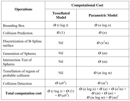
Table 3.1 Comparison of computational cost of collision detection for
tessellated model with the proposed algorithm. ... 54
Table 6.1 Computational time for collision detection of B-spline surface
having different number of control points with a point, a sphere,
and a plane. ... 94
Table 6.2 Computational time for collision detection of B-spline surface
having different number of the maximum points generated at lowest level of detail with a point, sphere, and plane. ... 98
Table 6.3 Comparison of the point set deviation of the merged surfaces
generated by Rhino® and the proposed algorithm. ... 106
Table 6.4 Comparison of the point set deviation of the merged surfaces
generated by Rhino® and the proposed algorithm. ... 112
Table 6.5 Computational time of the algorithm for merging B-spline surface
patches. ... 115
Table 6.6 Update time for single iteration of mass spring system for different
node sizes. ... 117
Table 6.7 Pre-processing time for generation of mass spring system for
different node sizes. ... 119
Table A.1 Comparison of the point set deviation of the merged surfaces
generated by Rhino® and the proposed algorithm for surface having similar curvatures and knot vectors. ... 169
Table A.2 Comparison of the point set deviation of the merged surfaces
generated by Rhino® and the proposed algorithm for surface
xv
generated by Rhino® and the proposed algorithm for surface
having similar curvature but different knot vectors. ... 171
Table A.4 Comparison of the point set deviation of the merged surfaces
generated by Rhino® and the proposed algorithm for surface
having similar curvatures but different knot vectors and dimensions. ... 173
Table A.5 Comparison of the point set deviation of the merged surfaces
generated by Rhino® and the proposed algorithm for intersecting
and trimmed surfaces. ... 174
Table A.6 Comparison of the point set deviation of the merged surfaces
generated by Rhino® and the proposed algorithm for surface
having different degrees. ... 175
Table A.7 Comparison of the point set deviation of the merged surfaces
generated by Rhino® and the proposed algorithm for multiple
xvi
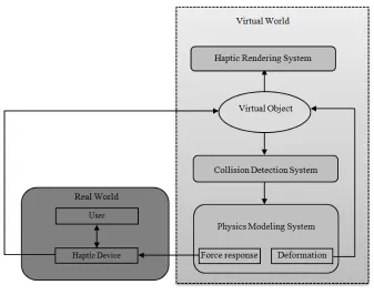
Figure 1.1 Basic architecture of a physics-based haptic system. ... 2
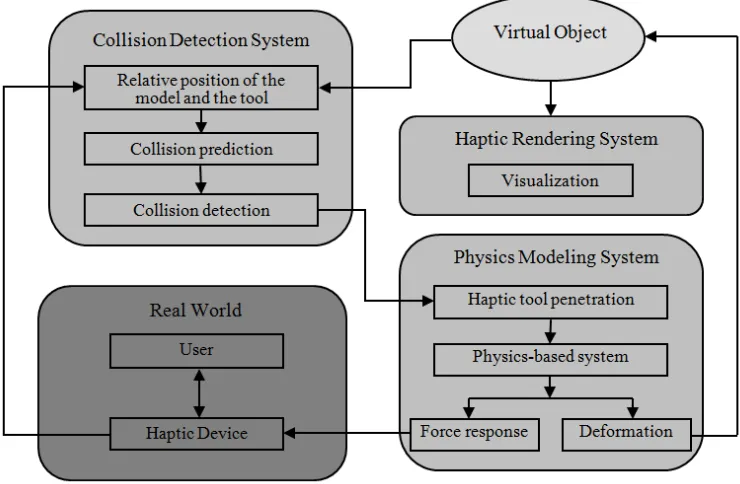
Figure 1.2 Schematic representation of a haptic interaction with a virtual object. ... 6
Figure 2.1 Haptic interaction with a virtual model through a haptic device (PHANTOM® Omni of SensAble Technologies, 2008) located at the University of Western Ontario. ... 13
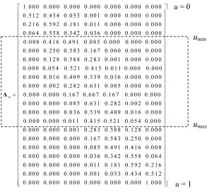
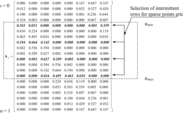
Figure 3.1 A typical blending matrix, Au. ... 37
Figure 3.2 Discretized B-spline surface. ... 38
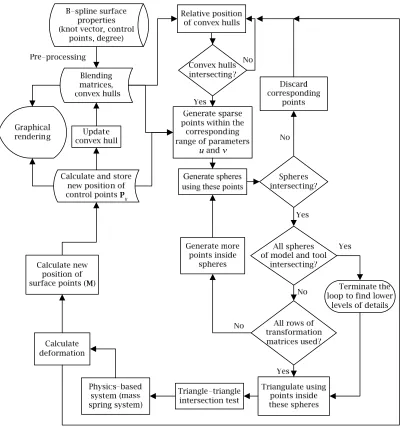
Figure 3.3 Flowchart of the proposed algorithm. ... 40
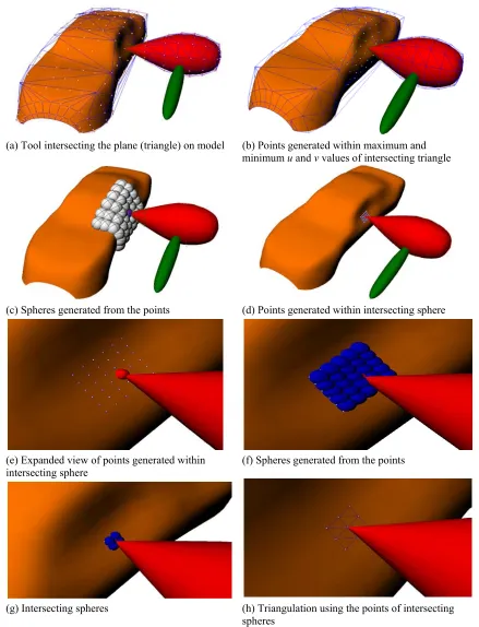
Figure 3.4 Illustrations showing the major steps in the proposed algorithm. ... 43
Figure 3.5 Selecting intermittent blending matrix for generation of points within the selected range of parameter u. ... 46
Figure 3.6 Generation of spheres using the points generated on the B-spline surface. ... 47
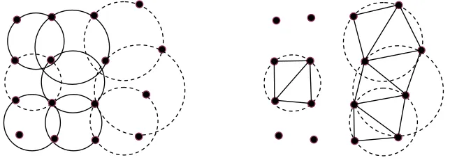
Figure 3.7 Triangulation using the points inside intersecting spheres. ... 50
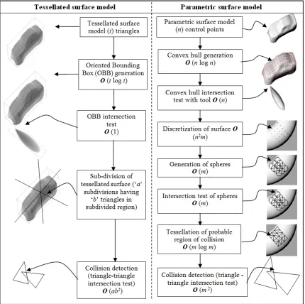
Figure 3.8 Comparison of steps for collision detection for tessellated model with proposed algorithm. ... 53
Figure 3.9 Comparison of total computations required in the worst case scenario for collision detection of tessellated model versus the B-spline model using proposed algorithm. ... 55
Figure 3.10 Maintaining lower number of computations required for collision detection by changing resolution of the surface. ... 56
xvii
surface patches. ... 64
Figure 4.3 (a) B-spline surface patches that are to be merged together (b)
Discretized points on the surface, as generated by using the blending matrices. ... 65
Figure 4.4 The effect of multiple knots at the common edge of the merging
surfaces. ... 67
Figure 4.5 (a) Intersecting surfaces to be merged (b) Region of the surface
selected for discretization (The points shown in red are discarded). ... 70
Figure 4.6 (a) Initial B-spline surface patches of order 4×4 and 5×6
respectively (b) Merged surface of order 5×6 with C4 connectivity
in v direction, generated by proposed algorithm. ... 72
Figure 4.7 (a) Initial multiple B-spline surface patches (b) Merged surface
with C2 connectivity generated by proposed algorithm. ... 74
Figure 5.1 Voigt model of mass spring damper system. ... 77
Figure 5.2 Flow chart for mass spring mesh generation and its integration with
collision detection algorithm. ... 80
Figure 5.3 (a) B-spline surface deformable model (b) Discrete points as nodes
for the mass spring system. ... 81
Figure 5.4 Generation of mass spring system. ... 83
Figure 5.5 A tool colliding with a deformable B-spline surface model. ... 84
Figure 5.6 Mapping of the sculpting force acting on B-spline surface to nodes
of mass spring system. ... 84
Figure 5.7 Hexahedral mesh and the node (mass) spring representation. ... 85
xviii
(spring stiffness = 13 MN/m2, density = 2500 kg/m3) while
applying different forces (F). ... 88
Figure 5.10 The deformation of the model with different spring stiffness, and
constant force (30 N) while pulling out the nose of the artifact. ... 89
Figure 6.1 Primitives (plane and sphere) and B-spline surfaces (a donut and a
distorted donut) for calculating time of collision detection. ... 92
Figure 6.2 Variation of the computational time of collision detection for a
point, sphere, and plane with respect to the number of control points used. ... 95
Figure 6.3 Variation of the computational time (ms) of collision detection for
a B-spline surface with another deformable B-spline surface for different number of control points. ... 97
Figure 6.4 A sphere colliding with (a) A tear shaped B-spline surface (b) A
deformed tear shaped B-spline surface. ... 98
Figure 6.5 Variation of the computational cost of collision detection for a
point, sphere, and plane with respect to the maximum number of
points generated. ... 99
Figure 6.6 Variation of the computational time(ms) of collision detection for a
B-spline surface with another deformable B-spline surface with
respect to the maximum number of points generated. ... 100
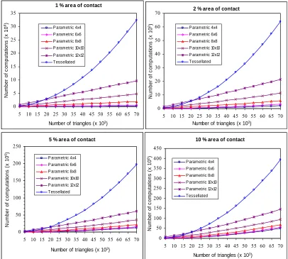
Figure 6.7 Variation of the computational time (ms) of collision detection for
a spline surface with a sphere, plane, and another deformable
B-spline surface for different percentage area of contact. ... 102
Figure 6.8 Variation of the computational time (ms) of collision detection for
a B-spline surface with a sphere, a plane, and another deformable B-spline surface for different percentage area of contact, when
xix
connectivity generated by Rhino® (c) Merged surface with C2
connectivity generated by proposed algorithm (d) Merged surface
with C0 connectivity generated by proposed algorithm. ... 105
Figure 6.10 (a) Initial B-spline surface patches (b) Merged surface with C2
connectivity generated by Rhino® after matching the surfaces (c)
Merged surface with C2 connectivity generated by proposed
algorithm (d) Merged surface with C0 connectivity generated by
proposed algorithm (e) Point set deviation for the C2 surface
generated by Rhino® after matching the surfaces (f) Point set
deviation for the C2 surface generated by proposed algorithm. ... 107
Figure 6.11 (a) Initial B-spline surface patches (b) Merged surface with C2
connectivity generated by Rhino® with increased knots (c) Merged
surface with C2 connectivity generated by proposed algorithm (d)
Merged surface with C0 connectivity generated by proposed
algorithm. ... 110
Figure 6.12 (a) Initial B-spline surface patches (b) Merged surface with C2
connectivity generated by the proposed algorithm. ... 111
Figure 6.13 (a) Initial B-spline surface patches (b) Merged surface with C2
connectivity generated by proposed algorithm. ... 111
Figure 6.14 (a) Initial B-spline surface patches (b) Merged surface of order
5×6, with C4 connectivity in v direction, generated by Rhino® with
increased knots (c) Merged surface of order 5×6 with C4
connectivity in v direction, generated by proposed algorithm (d)
Merged surface of order 4×4 with C2 connectivity generated by
proposed algorithm. ... 113
Figure 6.15 (a) Initial B-spline surface patches (b) Merged surface with C2
xx
different sizes. ... 120
Figure 6.17 (a) Deformable B-spline model (b) Points for collision detection (c)
Mass spring mesh. ... 121
Figure 7.1 Integration of various modeling techniques proposed in this thesis
to develop B-spline surface based interactive design module for various applications in virtual reality environment. ... 124
Figure 7.2 Photograph of typical commercially available spoons. Product
designs mainly focus on contemporary style, ease of use, and comfort of the user. ... 126
Figure 7.3 Generally accepted motions (a) Holding a spoon and (b) Rotating
wrist while eating (c) Rheumatoid arthritis restricts movements of fingers and wrist, modified picture from [Joint, Pain Solutions, 2010]. ... 127
Figure 7.4 Different methods to generate initial design represented as a
B-spline surface. ... 128
Figure 7.5 Parts of a spoon. ... 129
Figure 7.6 (a) Handle of spoon from the initial design (b) A plane is used to
fix nodes on one side of the plane (opposite to the direction of normal vector) and a sphere is used to apply force. ... 130
Figure 7.7 (a) Mass spring mesh for the spoon handle (b) Fixed nodes (green)
and the nodes colliding with the sphere tool (red) (c) Side view the
B-spline model showing fixed and colliding nodes. ... 131
Figure 7.8 Deformation of handle under the application of external force with
one end fixed. ... 132
Figure 7.9 Modified shape of spoon to accommodate lack of wrist movement. ... 133
Figure 7.10 Modifying the shape of spoon handle to grip it with all the fingers
xxi
model of a of spoon. ... 135
Figure 7.12 Investigation of different shapes of a spoon for eating food to
accommodate impaired wrist movements or weak grip of fingers. The original design is shown in (a) and design modifications are
presented from (b) to (d). ... 136
Figure 7.13 Investigation of different shapes of a serving spoon to
accommodate impaired shoulder movements. The original design is
shown in (a) and design modifications are presented in (b) and (c). ... 137
Figure 7.14 (a) B-spline model representing food (jelly) (b-c) Mass spring mesh
to incorporate material properties to the model. ... 138
Figure 7.15 Simulation of food (jelly) in a spoon without tilting it. ... 139
Figure 7.16 Simulation of food (jelly) in a spoon when the bowl is tilted by ten
degree. ... 140
Figure 7.17 Simulation of food (jelly) in a spoon when the bowl is tilted by
twenty degree. ... 141
Figure 7.18 Simulation of food (jelly) in a spoon when the spoon is tilted by
different degrees. ... 143
Figure 7.19 Simulation of food (jelly) in a spoon when the spoon is tilted by
CHAPTER 1 INTRODUCTION
1.1 Problem Statement
During the normal design phase, the designer has the freedom to generate and explore ideas without being constrained by parameters that exist at later design stages. At the conceptual stage, if a large number of ideas can be created, modified or analyzed; there will be more chances of finding the best possible design.
analysis. The objective of this thesis is to develop tools for a framework for an interactive design module in virtual reality environment. This will enable a designer to have natural and haptic modes of human-computer interaction for modeling and validating the conceptual designs. The proposed technique provides rapid verifications of the early design, before exchanging the information with commercially available CAD/CAM software to carry out detailed analysis and generate the final design.
Figure 1.1 shows the basic architecture of a typical physics-based haptic system. The haptic device works as an interface between the real and the virtual worlds. A collision detection algorithm then provides the contact information of the virtual tool with the object. The haptic device takes the force exerted by the user, converts it into appropriate signals and transmits the signal to the virtual object so as to make it deform (deformable bodies) or show resistance (rigid bodies). The force exerted by the user and position of interaction with the object are used by a physics-based model to calculate the deformation of the object and reactive forces to be sent back to the user.
Collision detection is an active research topic in engineering, computer graphics and virtual reality (VR) [Jimenez, 2001]. Collision detection is the necessary step before haptic interaction can be achieved. An efficient collision detection algorithm plays a very significant role towards achieving real-time haptic interaction. Most of the collision detection algorithms, available in literature, are mostly for rigid bodies. These rigid bodies are mostly represented as lower order implicit surfaces (spheres, cylinders, cones etc.) or tessellated surfaces. For applications in haptic-based modeling, mostly tessellated bodies are used, and many constraints are imposed on how the virtual model can deform.
Shape modification of a virtual object can be simulated using either geometric- or physics-based algorithms [Basdogan, 1998]. Geometric techniques only adjust the vertices of the underlying mesh model in response to external forces. The reaction force is typically determined using Hooke’s law where the depth of haptic tool penetration is calculated based on the current and home positions of the node that is nearest to the contact point. The concept was originally suggested by [Sederberg, 1986] and was further extended by [Basdogan, 1998; Basdogan, 2004] for applications in medical simulation. This technique, though computationally efficient, cannot determine real behavior of a multiple-material or non-homogeneous material virtual model. Physics-based models, on the other hand, are able to both estimate the direction and magnitude of nodal movement based on realistic material properties and the external forces introduced to the model through the haptic tool.
1.2 Basic Terminology
Conceptual Design is the early identification and generation of ideas for a design
solution. Virtual Reality (VR) is a technology that allows a user to interact with a
computer simulated environment representing a real or imaginary word. Haptics means
pertaining to touch. Haptic technology allows the user to interact with a virtual model via
a Haptic Device which works as an interface between real and virtual world. The user
feels the sense of touch through the application of force, vibrations, motion and resistance via a haptic device. Haptics has applications in the field of medicine (training for laparoscopic surgery), games, art, shape design and user training.
There are three distinct features that any haptics-based interactive design module
must have. The Haptic Rendering System is used for the visualization of the model and
the tool. Haptic Rendering includes graphics animation and haptic feedback. Through
haptic rendering, a user can feel and manipulate a virtual object using a haptic device. A
Collision Detection algorithm calculates the position and extent of the interference of the
virtual model(s) and the tool. A Physics-Based System uses the information provided by
the collision detection algorithm to determine the deformation of the model(s) and the
resultant reactive forces to be fed back to the user. Force Feedback is provided through
haptic devices. The nature and amount of force feedback depends upon the haptic device used, and the underlying algorithm used to calculate the force feedback.
1.3 Virtual Reality (VR) Environment
The goal of efficiently integrating sensory-motor functionalities and skills within a VR system poses extraordinary challenges for researchers and engineers in the field. There are many bottlenecks in efficient use of the virtual reality environment. Firstly, the real-time rendering of the complex word during simulation is not advanced enough for industrial applications. In the real word, people can use vision to estimate the distance between objects, and if, these are far or closer to them. The quality of the graphics has improved, of late, but still it has not reached the point of maturity.
The second bottleneck is in the implementation of collision detection algorithms. At present most of the algorithms are limited to particular applications. Most of these algorithms are for rigid bodies. When applied to deformable objects having complex surface, it may not be possible to get real-time interaction.
The third bottleneck is in providing physical properties to the virtual models. The sense of touch and force feed mechanisms allow the user, a rich experience in virtual world. However, to simulate the behavior of a real object, the simulation must include object rigidity/strength, mass, friction, surface texture, and heat transfer. Adding these physical characteristics to virtual objects require powerful computing hardware and efficient algorithms.
However, virtual reality development is a fast growing area in computer graphics and engineering. Already, it is being used for training for laparoscopic surgery and games. The interactive design through virtual reality promises to be very intuitive, creative, and cost effective method. With better integration with existing CAD/CAM software, it can provide a very effective way for the industrial designers and engineers to exploit their creativity. One way to achieve it is by using B-spline surfaces to represent virtual model and tool. The development of efficient collision detection and mass spring system to incorporate physical properties is described later in this thesis.
1.4 Haptics-based Interactive Design
user gets real-time visual and force feedback, while interacting with the virtual model. Haptics allows the user to benefit from the natural way of working with the model, without the constraints imposed by commercially available CAD/CAM software.
During traditional concept design phase, prototypes are sometimes built for conceptualization and preliminary validation of the idea which increases the time and the cost of the concept design phase and leads to the wastage of natural resources. The 3D visualization capabilities and the ability to directly interact with physics-based models using haptic tools suggest that Virtual Reality (VR) environments can provide new opportunities to assist the creative design process. Interactive modeling techniques, using the virtual reality, have rapidly evolved in recent times. This provides the designer, an insight to the physical characteristics of the concept, which can be evaluated before going in for a detailed design.
Figure 1.2 shows the schematic representation of a general framework for a haptic interaction with a virtual object.
There are three distinct features to enable any haptics interaction with a virtual object. As the user interacts with virtual object, the relative positions of the virtual tool
and the object are calculated. The collision detection system provides the information
regarding the details of the contact of the tool with the model and the tool penetration.
The physics-based system uses the information provided by the collision detection
algorithm to determine the deformation of the model(s) and the resultant reactive forces
to be fed back to the user. The haptic rendering system is used for the visualization of the
model and the tool.
1.5 Outline of the Thesis
The literature review, on virtual reality-based concept design, haptic interaction, virtual sculpting, surface representation techniques, collision detection and basic geometric- and physics-based modeling approaches, is discussed in Chapter 2. The chapter also summarises the approaches for haptics based shape design and development of deformable surface and solid models. The techniques discussed in the chapter includes collision detection of rigid and deformable bodies; implicit, tessellated and NURBS surface representation of virtual models; mass spring damper systems and finite element methods. The chapter also presents various types of surface representations of virtual models along with their relative merits and demerits and reasons of choosing B-spline surface representation for the haptic-based interactive design framework.
Chapter 3 introduces the collision detection algorithm for B-spline surface patches.
The algorithm is evaluated for its efficiency using the Big O notation for worst case
CHAPTER 2 LITERATURE SURVEY
2.1 Introduction
In addition to realistic three dimensional graphics, a virtual reality environment based interactive design must support visual object collision detection, physics-based modeling,
and haptic manipulation. The collision detection sub-system provides detailed
information about when and how multiple virtual objects make contact and interact
within the VR space. The physics-based sub-system uses the information provided by the
collision detection algorithm to determine the reactive forces to be fed back to the user
and degree of deformation of any non-rigid elastic and plastic objects. Finally, the haptic
rendering sub-system is used for tactile and visual interaction with virtual objects and tools used during the creative design exercise.
This chapter discusses the related research work involved in various aspects of a interactive design module. To better understand the idea behind the development of techniques for VR based interactive design and specific contribution of this thesis, it is necessary to review previous techniques used and their relative merits and demerits. Much of the work in rendering, sculpting, and collision detection has been in the field of computer graphics with applications in games and medical field in mind. Most of these techniques use tessellated surfaces for representing rigid bodies or deformable bodies with several constraints. The algorithms for rendering, collision detection, haptic interaction, and physics based system depend upon the type of surface representation of the models and tools in virtual reality environment.
2.2 Virtual Reality in Concept Design
systems concerns multimodal (real-time) sensory-motor interaction between the human operator (user) and the virtual environment. Such a natural and intuitive human/computer interaction should involve all the sensory channels of the human being.
During conceptual design, product specifications are not fully established and designers have significant freedom to change and modify the product configuration so as to meet the design requirements. Industrial designers tend to make extensive use of physical models created with their hands as it is natural and intuitive process. Unfortunately, current CAD and geometric modeling systems lack a natural and intuitive human-computer interface.
Initially, VR-enhanced 3D visualization and analysis systems were used, such as Virtual Design II [Astheimer, 1995], and ISAAC [Mine, 1997]. In these systems, the product models are initially created in existing 3D CAD systems and then appropriately translated into a VR environment. Such systems only permit designers to visualize and analyze CAD objects in a 3D virtual environment. Designers cannot directly create or modify pre-existing CAD models and so when any change or modification is required, they must go back to the conventional CAD systems.
and CUP [Anthony, 2001]. The 3DM allows the designer a better feel for the object's appearance in VR environment through a head mounded display. 3DM includes several grid and snap functions. It however lacks many other aids and constraints that are necessary to accomplish precise work. All of these techniques provide the designer with real-time interaction with the virtual object. However, each of these VR-based interaction techniques for CAD applications has its own potential and limitations. There is a limitation on the size of the model. When geometries get complex, a time lag sets into the system. Fully immersive design systems can create a more realistic environment but these often tend to make the system infrastructure more complex, cause uncomfortable intrusive viewing problems and make the system computationally expensive.
The Loughborough University Conceptual Interactive Design (LUCID) system [Ye, 2005; Ye, 2006a] was developed to integrate VR-based Human-Computer Interfaces (HCIs) into the design process in order to maximize its interactivity and efficiency so as to provide better support to conceptual design. It used a six degree of freedom (DOF)
SpaceMouse Classic® input device from 3Dconnexion Corp. to create a two-handed
operation mechanism. A 3D Phantom Desktop® haptic device from SensAble
Technologies Inc. was used to implement haptic interaction. A NuVision GX60®
stereoscopic display toolkit from MacNaughton Inc. was used to offer a stereoscopic display interface. A universal computer-supported speaker-based auditory system was employed to provide a sound feedback interface. This system can allow users to
experience 3D haptic force feedback from the 3D Phantom Desktop® haptic device and
navigate the virtual model through six DOF SpaceMouse Classic® input device.
Weidlich et al. [Weidlich, 2007] focused on integrating VR as a user interface into
the process of geometric modeling and detailing. It presents three paths towards a
solution: VRAx®, Navigation Interface for Modeling (NavIMode), and Construct|Tool.
Most of the preliminary work focused on the user interfaces and the modeling tools
for the designers. Sener et al. [Sener, 2002] conducted several case studies that pointed
CAD systems do not fulfill these expectations. Robinson et al. [Robinson, 2007] evaluated Co-Star, an immersive stereoscopic system for cable harness design. Overall, the results obtained and the positive experience of the participants indicated that 3D immersive design and direct body motion tracked interfaces did provide a very intuitive, easy to use, and useful addition to the technologies available to design engineers. Bourdot
et al. [Bourdot, 2010], presented an approach for the integration of Virtual Reality (VR) and Computer-Aided Design (CAD) by developing a VR-CAD framework. The framework allowed intuitive and direct 3D edition on CAD objects within virtual reality environments by combining the VR-CAD framework with multimodal immersive interaction (using 6 DoF tracking, speech, and gesture recognition systems) to gain direct and intuitive deformation of the objects' shapes within a VR environment. There are more research groups [Duriez, 2006; Gironimo, 2006] using virtual reality for concept design. Overall there is high demand for a virtual concept design tools in industry.
2.3 Haptic Interaction with Virtual Model
In the context of virtual reality applications, haptics is a force feedback technology which allows a user to use his/her sense of touch while interacting with a virtual model. By using haptics devices, the user can interact with a virtual model by feeding and receiving information through tactile/kinaesthetic sensation.
Figure 2.1 Haptic interaction with a virtual model through a haptic device (PHANTOM® Omni of SensAble Technologies, 2008) located at the University of Western Ontario.
method, which unfortunately implies potential under-sampling artifacts and storage problems. McCormack and Sherstyuk [McCormack, 1998] addressed this weakness by employing a new kernel function, called Cauchy function, and were able to deduce analytical solutions for several useful primitives, namely, points, line segments, polygons, arcs, and planes.
Field-based implicit surfaces have become an increasingly popular modeling approach [Bloomenthal, 1997a; Cani-Gascuel, 1997]. Their implicit representations, which have smooth-blending properties, make them convenient for modeling and animating smooth objects of complex topology that may change over time. Examples of such objects are liquids, clouds, plants, sea-life forms, and other organic shapes. In addition to object modeling, implicit surfaces have gained acceptance in other applications, namely, shape morphing [Turk, 1999b], surface reconstruction [Savchenko, 1995], natural phenomena simulation [Dobashi, 2000; Nishita, 1997], and space deformation [Jin, 2000]. Since implicit surface can produce visually striking special effects, they have become a powerful tool for animators.
Witkin et al. [Witkin, 1998] used a physically based particle approach to sample and
control implicit surfaces. On the other hand, Raviv and Elber [Raviv, 2000] presented an interactive sculpting algorithm that used a set of uniform trivariate B-spline functions as
the underlying representations. Martin et al. [Martin, 2001] used a trivariate spline based
mathematical framework to represent and extract volumetric attributes. Park and Kunwoo [Park, 1997] used high dimensional NURBS representation for analyzing and visualizing
fluid flow data. Schmitt et al. [Schmitt, 2001] presented an approach to constructive
modeling of FRep solids defined by real-values functions using 4D uniform rational cubic B-spline volumes as primitives. The first three coordinates are used to represent the spatial component of the volume to be sculpted and the fourth coordinate corresponds to
volume density. Knopf and Sangole [Knopf, 2002] investigated the Self Organization
Zhong et al. [Zhong, 2005] presented a methodology for solid modelling in a virtual reality (VR) environment in an intuitive manner through constraint-based manipulations. The data model integrates a high-level constraint-based model for precise object definition, a mid-level Constructive Solid Geometry/Boundary representation (CSG/Brep) hybrid solid model for hierarchical geometry abstractions and object creation, and a low-level polygon model for real-time visualization and interaction in the VR environment.
2.4 Virtual Sculpting
Mathematically, virtual sculpting refers to the dynamic manipulation of virtual object by the user to generate different shapes. Galyean and Hughes [Galyean, 1991] presented interactive modeling technique based on the notion of sculpting a solid material. A sculpting tool is controlled by a 3D input device and the material is represented by voxel data. The tool acts by modifying the values in the voxel array and particular attention was made to prevent aliasing when tool was re-sampled into the field grid. The tool was able to remove material as well as smoothen the surface through convolution. Wang and Kaufman [Wang, 1995] further extended haptic interaction to carving and sawing. The affected regions are indicated directly on the 2D projected image of the 3D model. The carving tools are pre-generated using a volume sampling technique and stored in a volume raster of 20 × 20 × 20 resolution. Avila and Sobierajski [Avila, 1996] used a force feedback articulated arm to command a tool in a similar context. However, the tool size was limited to 3-5 voxels because in order to meet the requirements of the system, the contents of each voxel must contain a large number of physical properties. This includes a scalar value for density, values for material classification and shading properties, as well as values for mechanical properties such as stiffness, and viscosity.
Multi-resolution surfaces have also been used to reduce computational cost of haptic interaction, particularly of collision detection. Baerentzen [Baerentzen, 1998] proposed an octree-based representation to accelerate ray-casting. The algorithm can be extended by allowing voxels to be inserted at different levels in the octree. This way, a sparsely
represented voxel raster with dynamic resolution, can be obtained. Raviv and Elber
[Raviv, 2000] proposed a hierarchical approach based on the combination of trivariate B-spline volumes to represent the field. This allows sculpting at different levels of details and arbitrary orientations. The presented approach provides the user with intuitive sculpting abilities in an interactive speed for modeling arbitrary geometries and/or
topologies. Ferley et al. [Ferley, 2001] proposed a sculpture metaphor based on a
multi-resolution volumetric representation. It allows the user to model both precise and coarse features while maintaining interactive updates and display rates. The modeled surface is an iso-surface of a scalar field, which is sampled on an adaptive hierarchical grid that dynamically subdivides or un-divides itself. Gao and Gibson [Gao, 2006] used multi-resolution B-spline surfaces to reduce the computational cost of haptic interaction. Though the multi-resolution techniques reduce the computation cost of haptic interaction, the haptic force to be fed back to the user is not realistic.
2.5 Surface Representations
A variety of techniques is available for representing the surface of a virtual object representing a model or tool. Each technique has its advantages and disadvantages with respect to other techniques. Before selecting any particular type of representation, it is necessary to compare the characteristics of these techniques and how these would fit in the overall picture of concept generation. Some of the prominent techniques are discussed in detail in the following subsections.
2.5.1 Implicit surfaces
generated using analytical, variational and multi-level partition of unity (MPU) approach. Implicit surfaces use 3D volumetric methods, 3D implicit primitives (e.g. blobby), level sets and radial basis functions to represent surfaces by superposition of weighted basis function. A consistent, smooth and water-tight surface can be represented using this approach.
An implicit surface consists of those points in three dimensional space that satisfy a
certain requirement represented mathematically by a function 'f ' whose argument is a
point 'p'. By definition, a point 'p' would lie on the surface if, f (p) = 0. The function 'f '
may contain any mathematical expression. These expressions can be polynomials or may include transcendental expressions such as trigonometric or exponential expressions. For
a continuous function 'f ', its value at any point 'p' is often a measure of proximity
between the point 'p' and the surface [Bloomenthal, 1997b]. This property is unique to the
implicit surfaces and can be very useful for collision detection. However the intersection test for implicit surfaces of degree higher than 3 is computationally very intensive.
An implicit surface naturally describes an object’s interior. The ability to enclose volume and to represent blends of volumes provides a straightforward implicit alternative
to fillets, rounds, and other ‘free-form’ parametric surfaces that require care in joining so
that geometric continuity is established along the seams [Charrot, 1984]. Consequently, animations of organic shapes commonly employ implicit surfaces. Several types of implicit surfaces have been described in the literature. They include metaballs, [Wyvill, 1989], distance surfaces [Bloomenthal, 1990], convolution surfaces [Bloomenthal, 1991], R-functions [Pasko, 1995], variational surfaces [Savchenko, 1995], and blob trees [Wyvill, 1999].
easier to draw, tessellate or to perform any operation that requires a knowledge of 'where' of the surface [Rockwood, 1989].
Manipulation of an implicit surface is complex because properties like surface point and its normal are not easily specified. Turk and O’Brien [Turk, 1999a] first presented the concept of variational implicit surfaces to handle this problem. Variational implicit surface facilitate direct specification of both the location of points on the surface and surface normals and are defined with additional interior and exterior constraints. They demonstrated the use of variational implicit surfaces for shaped transformation [Turk, 1999b]. This approach can successfully generate interpolating implicit surfaces [Turk, 2002]. Bloomenthal [Bloomenthal, 1999] used skeltonization as effective way for storing and manipulation and projected this technique for applications involving animation. Shen
et al. [Shen, 2004] developed a generalized approach of generating interpolating or
approximating implicit surface from polygonal data with moving least squares (MLS)
approach and iteratively fitted normal constraints. Implicit surfaces with sharp features are modeled by kernel approximation [Reuter, 2004] and dual-primal mesh optimization
[Ohtake, 2002]. Reuter et al. [Reuter, 2004] used MLS methods and integrated sharp
edges by specifying the implicit equation of half space that cuts the sharp edge with discontinuous implicit surface. Implicit surfaces are extensively used for character animations [Cani-Gascuel, 1997]. Implicit surfaces are generally used as an extra layer coating for any kind of structure that moves and deforms over time.
2.5.2 Tessellated surfaces
Tessellated surface modeling schemes attempt to interpolate the point clouds by mapping a flat 3D triangulated domain to generate 3D triangulated surface model. Delaunay and its derived methods are frequently used for generating triangulated surfaces. In Delaunay
triangulation, each triangle is generated from three points in the point set 'P' in such a
way that no other point from the data set 'P' lies within the circum-circle of the
because of inherent simplicity of triangle-triangle collision detection and advantage of hardware compatibility with tessellated models for rendering and graphical representations. However, there are many disadvantages of using tessellated surfaces while representing deformable surfaces. The most significant disadvantage of using tessellated model is that graphical rendering, collision detection and the number of nodes for mass spring system are all dependent upon the number of triangles used to represent a model.
The resolution of the surface cannot be changed during haptic interaction. A low resolution model can be used to decrease computation time. Conversely, a high resolution model can be used to increase accuracy of collision detection and better graphical representation. However, this trade off cannot be used during haptic interaction. Furthermore, as a tessellated surface model deforms during interaction with the tool or other model, the quality of the triangles deteriorate. This makes collision detection computationally extensive and inefficient. Other drawbacks of this approach include its incapability of modeling very smooth surfaces, and inability to represent smooth boundary edges.
2.5.3 Parametric surfaces
A parametric surface is a surface in the Euclidean space R3 which is defined by an
equation with two parameters. In other words a parametric surface is a function with
domain R2 and range R3. Typically variables u and v are used for the domain and x, y, and
z for the range. These notations have been used in this thesis. These surfaces require
fewer geometric parameters for their definitions. However, geometrically and topologically complex freeform surfaces cannot be represented with simple analytical surfaces (planes, quadrics, spheres, cones and cylinders etc.).
for surface representation. However, this modeling scheme has not emerged as an effecting modeling tool for B-spline based shape modifications mainly because of the computationally expensive collision detection and complexity involved in estimating controls points from for the deformed surface.
The general form of the parametric representation of a surface is p = p(u, v) = [x(u, v)
y(u, v) z(u, v)]T. There are many types of synthetic parametric surfaces such as, Bilinear
surfaces, Coons surface patches, Bicubic patches, Bezier surfaces, B-spline surfaces and NURBS surfaces [Farin, 1997; Piegl, 1997]. Of all these types of the surfaces, B-spline surfaces are the most widely used.
Over the past decade, B-spline representation has become the standard for CAD/CAM systems. Thus it is imperative that any haptic interactive design module should utilize a B-spline surface to represent the virtual model in order to streamline the exchange of the information with existing CAD/CAM systems. A major obstacle in using the B-spline surface to represent a deformable model is the absence of an efficient algorithm to detect collision between two or more B-spline surfaces having a complex surface. A collision detection algorithm must be capable of tackling complex surfaces, a large area of contact, multiple contacts, and high deformation.
2.6 Collision Detection
how the model representation leads to different collision detection algorithms. These algorithms were grouped into four approaches: space–time volume intersection, swept volume interference, multiple interference detection and trajectory parameterization.
In this chapter, the collision detection algorithms have been grouped mainly as rigid body algorithms and deformable model algorithms. Most of these algorithms fall in the former category and there are not many efficient collision detection algorithms for deformable bodies having complex surface. This section briefly discusses some of the important algorithms.
2.6.1 Collision detection of rigid bodies
Ho et al. [Ho, 1999] proposed a Neighbourhood Watch algorithm that was capable of
handling rigid bodies with both convex and concave surfaces. The Neighbourhood Watch
algorithm took advantage of pre-computed connectivity information for detecting collisions between the end effector of a force-reflecting robot and polyhedral objects in VR environment. Using this method and a haptic interface device, the users can manually explore and feel the shape and surface details of virtual objects. Mirtich [Mirtich, 1997] employed two phased approach to detect collision of rigid, polyhedral geometries. For the broad phase, an algorithm using axes-aligned bounding boxes (AABB) and a hierarchical spatial hash table was described. For the narrow-phase, primarily, the Lin-Canny algorithm [Lin, 1991] was used. Various bounding geometries and spatial geometries
help in performing a rejection test when two virtual objects are apart. Some of the
decomposition is used to perform a rejection test for decomposed/subdivided parts of the
objects. Gregory et al. [Gregory, 2000a] used a pre-computed hybrid hierarchical
representation, consisting of uniform grids and trees of tight-fitting Oriented Bounding Box Trees (OBB Trees). At run time, these hybrid hierarchical representations exploit frame-to-frame coherence for fast proximity queries. Ehmann and Lin [Ehmann, 2001] presented a unified approach to perform a set of proximity queries for general, rigid polyhedral objects. Hubbard [Hubbard, 1995] used simple four-dimensional geometry to approximate motion, and hierarchies of spheres to approximate three-dimensional surfaces at multiple resolutions. For time-critical algorithms, such as interruptible collision detection, there are distinct advantages in using hierarchies of spheres, known as sphere-trees. Quinlan [Quinlan, 1994] described an efficient algorithm for computing the distance between non-convex objects. Objects were modeled as the union of a set of convex components. From this model a hierarchical bounding representation based on
spheres was constructed. Bradshaw and O'Sullian [Bradshaw, 2002] also presented work
in Sphere-Tree construction and medial axis approximation using the Veronoї diagrams
[Okabe, 2000]. Hoffmann and Hopcroft [Hoffmann, 1987] approximated the object as the union of several cuboids enclosed by a single cuboid. The bounding geometry techniques work very well with rigid bodies but when applied to deformable bodies, the cost of updating these geometries, as the object deforms, slows down the collision detection response. If these bounding geometries are not updated in each frame to reduce the
computational cost, the overlapping of bounding volumes make the rejection test
inefficient.
2.6.2 Collision detection of deformable bodies
Larsson and Möller [Larsson, 2001] proposed and evaluated suitable bounding volume trees for deforming bodies that can be pre-built and then updated during simulation. The technique was used to address the collision detection problem in applications where deformable bodies are used, which change their overall shape at every time step of the simulation. Several heuristics for updating the trees due to deformations were compared to each other. Deformable objects are very challenging for BVH (Bounding Volume Hierarchies) because hierarchy structures (trees) have to be updated
when an object deforms itself. Teschner et al. [Teschner, 2005] presented various
approaches based on bounding volume hierarchies, distance fields, and spatial partitioning for deformable bodies and used the techniques for surgical and cloth simulations. Various bounding volumes were considered, in particular, OBBs and k-DOP's, and investigated for their efficiencies.
For parametric surfaces, Herzen et al. [Herzen, 1990] developed an algorithm to
detect geometric collisions between pairs of time-dependent parametric surfaces. It used the Lipschitz condition on a surface to create sets of bounding volumes that are guaranteed to bound the parametric surface. A surface-surface intersection test for a Bezier and B-spline surface by subdividing the surface patch till the sub-patches are sufficiently plane has also been proposed [Hughes, 1996]. The method constructed an AABB tree for each surface and used the pseudo-normal patch and Gauss map to detect self-collisions and the sweep-and-prune method to detect other collisions. However, the method needed to update the Axis Aligned Bounding Box (AABB) tree for each sub-patch and to find the solution of many algebraic equations for testing self collision. This made the algorithm computationally expensive. For complex surfaces, the number of levels needs to be high, further escalating the cost. As the model is deformable, the sub-patches that were plane initially may deform into curved surfaces and may no longer remain plane.
Thompson et al. [Thompson, 1997] used a tracing algorithm, supporting the
rendering of NURBS surface, which traced the closest point on a NURBS patch to the tool point. The system linked an advanced CAD modeling system with a Sarcos force-reflecting exo-skeleton arm. Initially a rough check for surface proximity was done using
order approximation to the closest point on the surface. Dachille et al. [Dachille, 2001] used a polyhedral representation which makes it easier to search for the nearest point on the surface, unlike the complicated NURBS surface intersection task proposed by Thompson [Thompson, 1997]. In this case the nearest point on the surface did not need to be updated too frequently, so the system could compute the distance from the cursor to all the vertices of the polyhedral representation. In both of the techniques, the interaction with the virtual model was only at a point through a point based tool. This limits the utility of the approaches, particularly in the area of 3D free form shape design where the sculpting activity is required to be done by hands or other surface based tools. Another shortcoming of point-surface interaction is the difficulty in anticipating results in advance. The user often does not know exactly if the deformation is going to be highly curved or flatter. Gao and Gibson [Gao, 2005; 2006] used a B-spline patch to represent the surface of a virtual model and an implicit surface to represent the virtual tool. Nodes were generated on the B-spline surface by discretization. These were used to incorporate a mass spring system and to detect collision by inputting these nodes in the equation of the implicit surface of the tool. This technique cannot be used when two or more B-spline surfaces are present in the virtual environment and are interacting with each other. Only rigid and lower degree (up to 2) implicit surface tools had been used and the collision detection technique did not allow a point based tool which further limited the scope of sculpting.
Galoppo et al. [Galoppo, 2007] used a two-level layered model representation. Low
resolution layer was used for the collision detection and the force response while the high resolution tetrahedral mesh was used to show deformation.
Recently specialized graphics processing units (GPUs) have been used for
processing bounding volume generation. Lauterbach et al. [Lauterbach, 2009] presented
two parallel algorithms for rapidly constructing bounding volume hierarchies on multi-core GPUs. This Linear Bounding Volume Hierarchy (LBVH) algorithm is focused on minimizing the cost of construction, while still producing BVHs of good quality. The algorithm was implemented in CUDA on an NVIDIA GeForce 280 GTX GPU to compute axis-aligned bounding boxes (AABBs). The algorithm was used for ray tracing
various approaches which use General-Purpose Processing on Graphics Processing Unit (GPGPU) and more recently using multi-core computers.
In general if the model is represented as a tessellated surface, the cost of updating the bounding box during deformation is very high. In case of a parametric representation of a deformable model, the collision detection techniques for B-spline intersection require to calculate computationally intensive blending functions. Hence the intersection test of two parametric surfaces is complex as compared to the simplicity and efficiency of triangle-triangle intersection test. The method proposed in this thesis uses the best of parametric representation of surface and efficiency of triangle-triangle intersection test.
2.7 Force and Deformation Modeling Techniques
Various techniques have been developed to generate fairly smooth surfaces and volumes that satisfy multiple constraints in deformable modeling. Shape modification of a virtual object can be simulated using either geometric- or physics-based algorithms. Sederberg and Parry [Sederberg, 1986] introduced free-form deformation by allowing object to change shape independent of its structure by embedding it in easily-parameterized domains. The scheme was based on trivariate Bernstein polynomials, and provided the
designer with an intuitive appreciation for its effects. Terzopoulos et al. [Terzopoulos,
1987] pioneered the work on physically-based deformable models in computer graphics. It applied the Lagrangian equations of motion using finite difference scheme to simulate elastic objects with regular parameterizations. This framework was further extended to include inelastic behaviours [Terzopoulos, 1988a] and to handle stiff rotating bodies using linearized equations [Terzopoulos, 1988b]. Physics-based deformation models give the designer, more opportunities to try different types of materials during the interactive design phase and validate product models in real-time. Major techniques and relevant research is presented in the following sub-sections.
2.7.1 Geometric deformation techniques
Computer Aided Geometric Design (CAGD), mostly parametric curves and surface patches such as Bezier, B-spline, Rational B-spline, and non-uniform rational B-spline (NURBS) are used to represent a model. The model can be deformed by moving the control points, adding or deleting the control points or changing weights of the control points. The model can also be deformed by changing the knot vector. However, this is a cumbersome process and a perceptually simple change may require significant and simultaneous adjustments of several control points.
Free-from deformation is a general geometric-based deformation method to deform objects. This method deforms the space in which the virtual model lies, thereby, deforming the model. Barr [Barr, 1984] presented this hierarchical solid modeling operations, which could simulate twisting, bending, tapering, or similar transformations of geometric objects. He used geometric mappings of three-dimensional space to examine model deformation. This mapping causes the objects to twist about z-axis. More complex deformations can be constructed by composing mappings. These operations extend the conventional operations of rotation, translation, Boolean union, intersection and difference. This technique can be applied to different graphical representations such as, points, polygons, splines, parametric patches, and implicit surface. Barr's method provides a powerful design tool, but the possible regions and types of deformation are limited. The user cannot control the deformations intuitively. Sederberg and Parry [Sederberg, 1986] introduced the term Free-Form Deformation (FFD). They generalized Barr's approach by embedding an object in a lattice of grid points of some standard geometry, such as a cube or cylinder. Manipulating nodes of the grid induces deformation on the space inside the grid, and these deformations transform the underlying primitives
that for the object. FFD involves a mapping from R3 to R3 through a trivariate tensor