ISSN(Online): 2319-8753 ISSN (Print): 2347-6710
I
nternational
J
ournal of
I
nnovative
R
esearch in
S
cience,
E
ngineering and
T
echnology
(A High Impact Factor, Monthly, Peer Reviewed Journal)
Visit: www.ijirset.com Vol. 8, Issue 1, January 2019
Dynamic Response Analysis of Centrifugal
Blower with Different Material
Md Adul Yakub Pasha 1, M G Mahesh 2,P Divakara Rao 3, D Bharath Reddy 4
Final year M.Tech Student, Department of Mechanical Engineering, J B Institute of Engineering Technology,
Moinabad, Hyderabad, India 1
Assistant Professor, Department of Mechanical Engineering, J B Institute of Engineering Technology, Moinabad,
Hyderabad, India 2
Head of Department (HOD), Department of Mechanical Engineering, J B Institute of Engineering Technology,
Moinabad, Hyderabad, India 3
M. Tech Student, Department of Mechanical Engineering, Newton’s Institute of Science and Technology, Macherla,
Guntur, India 4
ABSTRACT: Centrifugal blowers are utilized widely for on-board naval applications have high commotion levels.
The commotion created by a turning segment is primarily because of irregular stacking power on the blades and occasional cycle of approaching are with the blades of the rotor. The contemporary blades in naval applications are comprised of aluminum or steel and create commotion that makes disturbance to the general people working close to the blower.
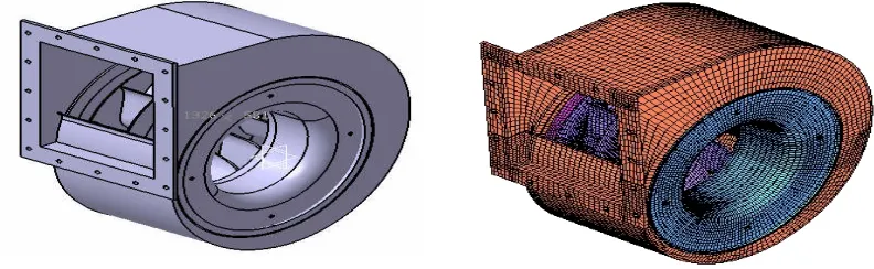
The present work aims at examining the choice of composites as an alternative to metal for better vibration control. Composites, known for their superior damping characteristics are more promising in vibration reduction compared to metals. The modeling of the blower was done by using solid modeling software, CATIA V5 R20. The blower is meshed with a three dimensional hex8 mesh is done using HYPERMESH 17.
It is proposed to design a blower with composite material, analyze its strength and deformation using FEM software. In order to evaluate the effectiveness of composites and metal blower using FEA packaged (ANSYS). Modal analysis is performed on both Aluminum and composite blower to find out first 6 natural frequencies.
KEYWORDS: BLOWER, CATIA, ANSYS, Natural frequency, Harmonic Analysis.
I. INTRODUCTION
Blowers are one of the mechanisms utilized routinely in submarines. They are introduced in ventilation and cooling systems in every single submarine compartment. Ventilation systems typically exhibited by focal systems incorporate supply and fumes fans, serve for ventilation of settlement and other than convenience regions with climatic air with synchronous ventilation of capacity batteries and for air cooling and refinement from unsafe and smelling polluting influences. Cooling systems are exhibited by neighborhood, compartment gathering and single channel systems. These systems are utilized to give agreeable conditions as far as air temperature and stickiness for the group in settlement territories and other convenience regions, air purging in galleys, arrangement rooms, and clean regions and furthermore for air blending in compartments.
ISSN(Online): 2319-8753 ISSN (Print): 2347-6710
I
nternational
J
ournal of
I
nnovative
R
esearch in
S
cience,
E
ngineering and
T
echnology
(A High Impact Factor, Monthly, Peer Reviewed Journal)
Visit: www.ijirset.com Vol. 8, Issue 1, January 2019
expansive piece of submarine mechanisms, they should normally meet the accompanying obligatory necessities for all mechanisms:
1. Minimum weight-dimensional parameters. 2. Reliable operation at submarine motions. 3. Vibration and impact resistance.
4. Convenience of mountings, repairs and easy access to lubrication points. 5. Keeping of service life at transportation and changes in climate.
II. CAUSES OF NOISE GENERATION IN CENTRIFUGAL BLOWER
1. Tonal noise caused by rotational frequency and fan cutting edge passing frequency (BPF) and their harmonics. These are typically the overwhelming noise source.
2. Broadband aerodynamic noise created via wind current at the delta and outlet of the cooling fan.
3.Mechanical noise caused by contact in course and seals, vibration because of engine fan static and dynamic uneven pivoting masses, full vibration of engine fan housings, engine fan mounting and misalignment, and so forth. 4. Electromagnetically produced noise caused by changing of electromagnetic field in the electric engine.
Noise control techniques
Environmental noise generally does not exude specifically from the vitality source rather; it transmitted along mechanical or fluid ways before it at long last emanates from some vibrating surface into the encompassing condition. The ways to deal with treating pump noise for the most part incorporate the accompanying:
1. Modify the fundamental design or working condition to limit the age of acoustic vitality.
2. Prevent sources from producing airborne noise by interfering with the way between the vitality source and the audience. This methodology may run from separation mounts at the source to physically expelling the audience.
III. ROLE OF COMPOSITE MATERIALS IN NOISE SIGNATURE CONTROL
Composite material is a framework that is made by the synthetic gathering of at least two materials. The material comprises of fiber of high quality and modulus installed in a tar with particular interfaces between them. They create a blend of properties that can't be accomplished with both of the constituents acting alone. Composite materials have high quality, modulus. The most well-known shape in which fortified composites are utilized in auxiliary application is known as an overlay and it is gotten by stacking various thin layers of fibers and lattice and combining them into the ideal thickness. Fiber introduction in each layer and stacking grouping of different layers can be controlled to get a wide scope of physical and mechanical properties for the composite cover. These materials are found to have high damping co-effective. The damping property of a material speaks to its ability to decrease transmission of vibration caused by mechanical unsettling influences to a structure. The proportion of damping of a material is its damping factor. Expanding the estimation of ή is alluring for decreasing the reverberation sufficiency of vibration in a structure.
Damping factor esteem relies upon various components, including fiber and tar types, fiber introduction point, and stacking grouping.
IV. TYPES OF BLOWERS
Blowers can accomplish a lot higher weights than fans, as high as 1.20 kg/cm2. They are additionally used to create negative weights for mechanical vacuum systems. The centrifugal blower and the positive relocation blower are two principle sorts of blowers, which are depicted underneath.
Centrifugal blowers
ISSN(Online): 2319-8753 ISSN (Print): 2347-6710
I
nternational
J
ournal of
I
nnovative
R
esearch in
S
cience,
E
ngineering and
T
echnology
(A High Impact Factor, Monthly, Peer Reviewed Journal)
Visit: www.ijirset.com Vol. 8, Issue 1, January 2019
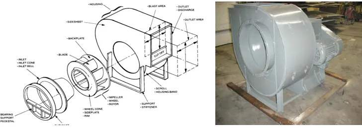
V. PRINCIPLE OF CENTRIFUGAL BLOWER
Working principle is a blend of two effects: Centrifugal force which creates progressively static pressure and again avoidance of the air flow by the blades, however here the diversion is from a radially outward heading into a winding flow pattern. In the event of forward bended blades the air deflections impact the flow pattern and on the execution.
Flow pattern in centrifugal blower
The air flow enters the blower unit pivotally, equivalent to in a hub flow fan, yet then spreads out in a channel formed pattern, transforming 900 into different radially outward headings previously meeting the blades. The blades at that point avoid these individual air streams into a winding pattern to a relatively circumferential course. All these air streams are at last gathered by parchment lodging and are brought together into a solitary air stream that leaves the unit at a correct edge to the axis.
Fig 1 Parts of centrifugal blower
Disadvantages of blower
Most noise issues can be displayed as source way beneficiary systems. It is most attractive to lessen the quality or number of the sources. For instance, supplanting either of the metal contacts with milder material, for example, nylon or solid tough plastic may diminish the noise from the effect of two metal machine parts in punch press. Be that as it may, it is at times hard to lessen the noise at a source without broad redesign. Sound waves have a successful range in water more noteworthy by a few requests of greatness than electromagnetic waves.
VI. OVERVIEW OF COMPOSITE MATERIALS
Fiber reinforced composite material comprises of fibers of high quality and modulus inserted in or attached to a matrix with unmistakable interfaces between them. In this shape, the two fibers and matrix hold their physical and compound personalities, yet they create a mix of properties that can't be accomplished with both of the constituents acting alone. All in all, fibers are the foremost load conveying individuals; while the encompassing matrix keeps them in wanted area and introduction, goes about as a load exchange medium among them and shields them from environmental harms because of lifted temperatures and moistness. Along these lines, despite the fact that the fibers give reinforcement to the matrix, the last likewise serves various helpful capacities in a fiber reinforced composite material.
Each layer may vary from the other in
a) Relative volumes of the constituent materials
ISSN(Online): 2319-8753 ISSN (Print): 2347-6710
I
nternational
J
ournal of
I
nnovative
R
esearch in
S
cience,
E
ngineering and
T
echnology
(A High Impact Factor, Monthly, Peer Reviewed Journal)
Visit: www.ijirset.com Vol. 8, Issue 1, January 2019
E Glass /Epoxy
Ultimate Strength =380MPa Ultimate compressive Strength
= 350MPa
Ultimate Transverse Tensile Strength
= 380MPa Ultimate Transverse Compressive strength
= 350MPa
Ultimate Inplane Shear =54MPa Ultimate strength in Z direction
= 62MPa
Ex = Ey = 14Gpa Ez = 8.8Gpa
NUXY = 0.13 NUYZ=NUZX = 0.39
Gxy = 4.7Gpa Gyz=Gzx = 4.2Gpa
VII. PROBLEM FORMULATION
In the present problem, metal blower is used for air conditioning and ventilation purpose in naval defence applications causes vibration and noise during its operation which causes mental imbalance to the people working near the blower on ship. Therefore reducing vibration from a source is very important and critical task. Hence the objective of this project is to reduce the vibration level produced by metal air blower. It can be effectively reduced by the modifying the shape of blades.
Scope of the project
The scope of the project is as follows:
a) To analyze the displacement and stresses of composite blower and compared with Aluminium blower. b) Comparing natural frequencies of both Aluminium and composite blower.
c) To study the vibration reduction due to composite blower instead of Aluminium blower.
ISSN(Online): 2319-8753 ISSN (Print): 2347-6710
I
nternational
J
ournal of
I
nnovative
R
esearch in
S
cience,
E
ngineering and
T
echnology
(A High Impact Factor, Monthly, Peer Reviewed Journal)
Visit: www.ijirset.com Vol. 8, Issue 1, January 2019
Material properties of the blower
Table 2: Metallic blower and Composite bloweri) Material properties of metallic blower: (aluminium)
Material properties of Aluminium
blower:
Material properties of composite blower: (Glass/epoxy)
Young’s modulus (E) = 70000 MPa Young’s modulus Ex ,Ey = 14Gpa, Ez = 8.8Gpa
Poisson’s ratio NUXY =0.34 Poisson’s ratio NUXY 0.13, NUYZ=NUZX = 0.39 Mass density =2700 kg/m3 Mass density =1750 kg/m3
Damping co-efficient =0.006 Damping co-efficient =0.02
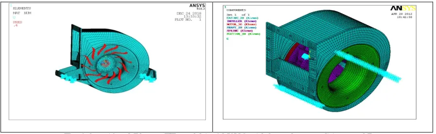
Boundary conditions and loads in ansys
The centrifugal blower is fixed at support plates on the casing so all DOF condition is applied to the nodes near the support plates. An UX is constrained to the shaft because for 3D elements rotation is not possible to apply. Pressure is applied to the total blower which is obtained from the CFD analysis. The boundary conditions and pressures are as shown below.
Fig.4 Centrifugal Blower FE model in ANSYS with boundary conditions and Pressures
Analysis of centrifugal blower
The analysis of centrifugal blower has been carried out by using ANSYS 11.0 general purpose FEM software. The following analysis were done on the blower
1) Modal analysis 2) Harmonic analysis
VII. RESULTS & DISCUSSIONS
Centrifugal blower made of Aluminum and another one made of composite material is chosen for FE analysis. In this work the results of modal and harmonic analysis are presented using ANSYS software.
First six natural frequenies of composite blower
ISSN(Online): 2319-8753 ISSN (Print): 2347-6710
I
nternational
J
ournal of
I
nnovative
R
esearch in
S
cience,
E
ngineering and
T
echnology
(A High Impact Factor, Monthly, Peer Reviewed Journal)
Visit: www.ijirset.com Vol. 8, Issue 1, January 2019
Table 3: Natural frequencies of Composite blower
No. of modes Natural frequencies of Composite
blower in Hz
No. of modes Natural frequencies of Composite
blower in Hz
1 178.695 4. 228.332
2. 178.716 5. 288.078
3. 189.216 6. 297.619
ISSN(Online): 2319-8753 ISSN (Print): 2347-6710
I
nternational
J
ournal of
I
nnovative
R
esearch in
S
cience,
E
ngineering and
T
echnology
(A High Impact Factor, Monthly, Peer Reviewed Journal)
Visit: www.ijirset.com Vol. 8, Issue 1, January 2019
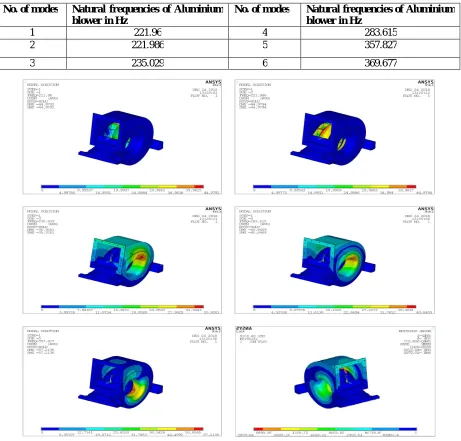
Table 4: Natural frequencies of Aluminium blower
No. of modes Natural frequencies of Aluminium
blower in Hz
No. of modes Natural frequencies of Aluminium
blower in Hz
1 221.96 4 283.615
2 221.986 5 357.827
3 235.029 6 369.677
ISSN(Online): 2319-8753 ISSN (Print): 2347-6710
I
nternational
J
ournal of
I
nnovative
R
esearch in
S
cience,
E
ngineering and
T
echnology
(A High Impact Factor, Monthly, Peer Reviewed Journal)
Visit: www.ijirset.com Vol. 8, Issue 1, January 2019
Table 5: Comparison of natural frequency of aluminum and composite blower
VIII. OBSERVATIONS
The following conclusions are drawn from the present work
1. The natural frequency of composite blower is reduced because of high stiffness and the lay up sequence in the blower.
2. The First mode of Aluminum is 128.11 and First mode is composite is 94.466.From above values we can say composite is more stable than the Aluminum.
3. Up to 3 modes the Natural Frequency of Aluminum and Composite are stable and after that Aluminium is gradually increasing more than the composite materials as shown in the Figure 6.23.
4. The weight of the Composite blower is 15 kg which is less than the aluminium blower with a weight of 20 kg.
IX. CONCLUSION
The natural frequency of E-Glass blower is reduced by 26.6% to 47.7% because of high stiffness and the lay-up sequence in the blower. The weight of the E-Glass blower is 15 kg which is less than the Aluminium blower with a weight of 20 kg. From the results of harmonic analysis, damping effect is more in E-Glass blower which controls the vibration levels. From the above results we can conclude that E-Glass blower is preferable than Aluminium blower and based up on frequency values can be reduced.
X. FUTURE SCOPE OF WORK
In Future work blower can be done the harmonic analysis is carried out for both aluminum and composite blower and response is compared. The aerofoil blade profile may be used for impeller blade and further solution is required. However, all those papers mostly concentrated on aero acoustics only. So the future work concentrates on structural vibration due to the flow inside the blower by using CFD results obtained in Fluent.
REFERENCES
1. Huang Chen-Kang and Hsieh Mu-En, “Performance analysis and optimized design of Backward curved airfoil centrifugal blowers”, American society of Heating, Refrigerating and Air Conditioning Engineers, May 1, 2009
2. Preseli Jurij and Carolina Mirko, “Identification of noise sources in centrifugal blower with acoustic camera”, The Journal of Acoustical Society of America, Volume 123, Number 5, p. 3824, May 2008.
3. J.B. Moreland, “Housing effect on centrifugal blower noise”, Journal of Sound and Vibration, Volume 36, Number 2, pp. 191-205,22 September 1974.
4. G. H. Koopmann and W. Neise, “The use of Resonators to silence centrifugal blower”, Journal of Sound and Vibration, Volume 82, Number 1, pp. 17-27, 8 May 1982.
5. Renjing Cao and Jun HU, “A cluster design approach to noise reduction in centrifugal blower”, International Journal of Ventilation, Volume 3, Number 4, pp. 345-352, 2005.
No. of modes Natural frequencies of Aluminum
blower in Hz
Natural frequencies of Composite blower in Hz
%Variation
1 221.96 178.695 19.492
2 221.986 178.716 19.492
3 235.029 189.216 19.492
4 283.615 228.332 19.492
5 357.827 288.078 19.492
ISSN(Online): 2319-8753 ISSN (Print): 2347-6710
I
nternational
J
ournal of
I
nnovative
R
esearch in
S
cience,
E
ngineering and
T
echnology
(A High Impact Factor, Monthly, Peer Reviewed Journal)
Visit: www.ijirset.com Vol. 8, Issue 1, January 2019
6. T. F. W. Embleton, “Experimental study of noise reduction in Centrifugal Blowers”, The Journal of Acoustical Society of America, Volume 35, Number 5, pp. 700-705, May 1963.
7. Q. Datong, Mao Yijun, Liu Xiaoliang and Yuan minjian, “Experimental study on the noise reduction of an industrial forward-curved blades centrifugal fan”, Applied Acoustics, Volume 70, Number 8, pp. 1041-1050, August 2009.
8. Sandra velarde, Rafael Ballesteros, Carlos Santolaria and Bruno pereiras, “Reduction of aerodynamic Tonal Noise of a forward curved centrifugal fan by modification of the volute tongue geometry”, FEDSM2005-77436, 2005 ASME Fluids Engineering Division Summer Meeting and Exhibition June 19-23, 2005, Houston, TX, USA
9. Michel Tournour, Zoubida El Hachemi, Alex Read, Fred Mendonca, Fabio Barone and Paolo Durello, “Investigation of tonal Noise radiated by subsonic fans using the Aero-Acoustic analogy”, FAN NOISE 2003 International Symposium Senlis, 23-25 September 2003.
10. Raymond A. Loew, Joel T. Lauer, Joseph McAllister and Daniel L. Sutliff, “Advanced noise control Fan”, Twenty-Fifth Aerodynamic Measurement Technology and Ground Testing Conference sponsored by the American Institute of Aeronautics and Astronautics, San Francisco, California, June 5- 8, 2006.
11. Jeon Wan-Ho and Lee Duck-Joo, “A numerical study on the flow and sound fields of centrifugal impeller located near a wedge”, Journal of sound and vibration, Volume 266, Number 4, pp. 785-804, 2003
12. Christopher L. Banks and Sean F. Wu, “Prediction and reduction of centrifugal blower noises” Journal of Acoustical Society of America, Volume 103, Number 5, pp. 3045-3045, May 1998.
13. Jianfeng MA, Datong QI and Yijun MAO, “Noise reduction for centrifugal fan with non-isometric forward-swept blade impeller”, Energy Power Engineers, Volume 2, Number 4, pp. 433–437, 2008.
14. M. Carudina, “Noise generation in vane axial fans due to rotating stall and surge”, Journal of Mechanical Engineering Science, Volume 215, Number 1, pp. 57-64, 2001.