Multi-turn track fitting for the COMET
experiment
Yao Zhang1,*,Yohei Nakatsugawa1, Haibo Li1, Ye Yuan1, and Tianyu Xing1 1Institute of High Energy Physics, CAS, China
Abstract. The reconstruction of multi-turn curling tracks is a big challenge for the drift chamber of the COMET [1] experiment. A method of deterministic annealing filter that implements a global competition between hits from different turns is introduced. This method assigns the detector measurements to the candidate track based on the weighted mean of fitting quality on different turns. We present here the study of multi-turn track fitting based on the simulated tracks. We found that the algorithm can successfully distinguish the hits from different turns.
1 Introduction
1.1 Overview of the COMET experiment
The observation of charged-lepton flavour violation (CLFV) would imply the need for an ambitious extension of the SM. The COMET experiment is designed to search for a CLFV transition through a neutrino-less muon to electron conversion in the presence of a nucleus
N> eN. The event signature of muon to electron conversion is a 105 MeV mono-energetic electron generated in the field of an Al nucleus. The search for this process will reach the sensitivity of 3.1x10⁻¹⁵ for the COMET Phase-I. The experiment will take place at the J-PARC laboratory in Tokai, Japan using a pulse bunched 8 GeV proton beam slow-extracted from the J-PARC main ring. Due to the feature of a pulsed beam, the prompt beam backgrounds can be eliminated by looking at tracks that are delayed by several hundred nanoseconds from the prompt beam flash.
1.2 Cylindrical drift chamber for the COMET experiment
The Cylindrical Detector system (CyDet) for the COMET Phase-I consists of a Cylindrical Drift Chamber (CDC) and a set of trigger hodoscope counters. Fig. 1 shows a schematic
layout of the CyDet. It is located at the end of the muon transport section, surrounded by a 1 Tesla superconducting detector solenoid that surrounds the stopping target. The muon-stopping target is placed in the centre of the detector solenoid. The configuration and dimensions of the muon-stopping target have been optimised, resulting in a system of 17 thin flat circular disks with 100 mm radius, 200 mm thickness, and 50 mm disk spacing.
Fig. 1. A schematic layout of the CyDet.
The CDC is designed with a large inner radius to be able to withstand the large flux of charged particles during the burst of "beam flash" particles; more details are in Table 1. The CDC is arranged in 20 concentric sense layers (including two guard layers) with alternating positive and negative stereo angles. The stereo angle is set to 64~75 mrad to achieve a longitudinal spatial resolution in the direction to the beam axis of about 3 mm. In total there will be 4,986 sense wires and 14,562 field wires. The CDC with only stereo layers is adopted to provide a good momentum resolution. The chamber gas is filled with He : iso-butane (10 : 90) to reduce the energy loss. The cell size is 16.8 mm wide and 16.0 mm in height and nearly constant over the entire CDC region. Square cells are well-suited to the low momentum tracks which can enter the drift cells at large angles with respect to the radial direction.
Table 1. Main parameter of the CDC.
Length Spacing Thickness
Inner wall 1495.5 mm 496.0~496.5 mm 0.5 mm
Outer wall 1577.3 mm 835.0~840.0 mm 5.0 mm
2 Multi-turn track fitting of the COMET experiment
Track reconstruction of the CDC of COMET is challenging due to features of the signal tracks and design of the tracking detector. The reasons for the challenge include: 1) Transverse momentum cannot be calculated analytically due to the all-stereo wire design. So the estimation of transverse momentum and longitudinal momentum must be achieved iteratively. 2) More than one third of the signal tracks are multi-turn tracks and hits from different turns are close to each other, and some even overlap. Thus the quality of tracking is strongly related to the efficiency and purity of clustering for the hits from the same turn.
3) The 105 MeV/c signal tracks are curled in the CDC which adds more complication to the tracking compared with straight tracks. 4) The track primary vertex position has a large range from -400 mm to 400 mm in Z and the maximum 100 mm in radial.
A method to determine the CDC multi-turn track reconstruction will be introduced in this paper. At first, we need to find the series of hits corresponding to the tracks, and to form groups of sense wires included in each track, collectively called track finding. After track finding, the momenta of electrons are estimated by track fitting of these wire groups with Kalman filtering [2] under the magnetic field. Track candidates which come from the same particle will be fitted simultaneously and the assignment of the shared hits to the tracks is made during track fitting.
2.1 Multi-turn track finding
The initial track parameter estimation for track fitting is designed as follows: First we take the closest points between the hits from adjacent layers and do a rough circle estimation by Hough transform. Once the circle parameter is given, the 3-dimensional positions of hits can be calculated using the wire angle. The linear fitting is performed in φ-Z space by picking up 6 hits from entrance and exit parts of the track with the circle parameter kept free. By made a 2-dimensional histogram of line parameters for all combinations of 6 hits, peaks corresponding to each turn can be found. After peak-finding in the line parameter space, all initial helixes are available for each turn and the hits close to the helix are selected. Fitting with an ideal helix model is performed for selected hits and the helix parameters are updated.
2.2 Multi-turn track fitting
It has been shown that parameters of isolated tracks can be estimated through an iterated non-linear filter with the Deterministic Annealing Filter (DAF) [3] while outlier hits are rejected, i.e. separate out the hits corresponding to different turns and noise. According to a previous study of adaptive multi-track fitting [4] for the Transition Radiation Tracker (TRT) in ATLAS, for overlapping pairs of tracks the Elastic Arms algorithm (EAA) one can solve the hit assignment problem by introducing a global competition between tracks and hits at each detector layer. The multi-turn track fit is proposed to be an iterative procedure of DAF or EAA. Starting with the track candidates from different turns from the track which mainly differ in the initial position in the first layer of each turn. We take the parameters of one track for a certain turn as one track candidate. We compute the initial assignment probabilities of all candidate hits to all candidate tracks from different turns from the initial track parameters. These assignment probabilities are used as weights in the estimation of all track parameters. A hit which has a small assignment probability with respect to a certain candidate track thus contributes very little to the estimate of this track’s parameters. We now define the scheme for hit competition and a method for computing the assignment probabilities.
2.2.1 Hit competition
y = Hx +
where H is the liner function between measurement y and track parameter x, is the wire measurement error which is assumed to be normal with zero mean and covariance matrix V.
As a preparation for computing the assignment probability pij between hit i and track candidate j we set up the following matrix , which has a row for each hit and a column for each track candidate:
()ij = ij = (yi; Hxj ,V
where (yi; Hxj ,Vis the multivariate normal probability density with mean vector μ and covariance matrix V.
2.2.2 Hit assignment probability
Since one hit could be shared by different turns of tracks, there is the competition between all tracks for each hit. For drift chamber and drift tube the competition between a hit and its mirror hit (from further left-right ambiguity) should be considered as well. The assignment probabilities are computed separately for each of pair of hit and mirror hit. If (i1, i2) is such a pair, the assignment probabilities are computed according to
(3) Where c is the normalization constant which sum all the related elements in the respective probability submatrix plus a constant. The constant c is a cut to make the assignment probability quickly drop to 0 when the probability summation is larger than c. All hits with non-zero assignment probability are combined to a single track point by a weighted mean, the weights being proportional to the respective assignment probabilities. The combined track point is then used in the Kalman filter estimation of the track parameter of all the track hypotheses from different turns. The procedure is carried out with annealing iterated until the assignment probabilities have converged to their final value.
2.3 Implementation of multi-turn track fitting with GENFIT2
GENFIT [5] is a generic track-fitting toolkit for track fitting and is independent of the event topology, detector setup, ormagnetic field arrangement. GENFIT contains the track fitting algorithms, the track representations and the representations of detector hits. The basic functionalities of GENFIT are to extrapolate the tracks to the positions of the hits in the detectors, and calculate the distances between hits and tracks. Detectors which measure a drift time relative to a wire past which the particle passed tangentially, like drift chambers or straw tubes, are supported. The GENFIT2 [6] package is a major upgrade of GENFIT with a deterministic annealing filter implemented. GENFIT2 is chosen to be used for CDC and Straw Tracker fitting for the COMET. The multi-turn track fitting implementation is based on GENFIT2 package.
y = Hx +
where H is the liner function between measurement y and track parameter x, is the wire measurement error which is assumed to be normal with zero mean and covariance matrix V.
As a preparation for computing the assignment probability pij between hit i and track candidate j we set up the following matrix , which has a row for each hit and a column for each track candidate:
()ij = ij = (yi; Hxj ,V
where (yi; Hxj ,Vis the multivariate normal probability density with mean vector μ and covariance matrix V.
2.2.2 Hit assignment probability
Since one hit could be shared by different turns of tracks, there is the competition between all tracks for each hit. For drift chamber and drift tube the competition between a hit and its mirror hit (from further left-right ambiguity) should be considered as well. The assignment probabilities are computed separately for each of pair of hit and mirror hit. If (i1, i2) is such a pair, the assignment probabilities are computed according to
(3) Where c is the normalization constant which sum all the related elements in the respective probability submatrix plus a constant. The constant c is a cut to make the assignment probability quickly drop to 0 when the probability summation is larger than c. All hits with non-zero assignment probability are combined to a single track point by a weighted mean, the weights being proportional to the respective assignment probabilities. The combined track point is then used in the Kalman filter estimation of the track parameter of all the track hypotheses from different turns. The procedure is carried out with annealing iterated until the assignment probabilities have converged to their final value.
2.3 Implementation of multi-turn track fitting with GENFIT2
GENFIT [5] is a generic track-fitting toolkit for track fitting and is independent of the event topology, detector setup, or magnetic field arrangement. GENFIT contains the track fitting algorithms, the track representations and the representations of detector hits. The basic functionalities of GENFIT are to extrapolate the tracks to the positions of the hits in the detectors, and calculate the distances between hits and tracks. Detectors which measure a drift time relative to a wire past which the particle passed tangentially, like drift chambers or straw tubes, are supported. The GENFIT2 [6] package is a major upgrade of GENFIT with a deterministic annealing filter implemented. GENFIT2 is chosen to be used for CDC and Straw Tracker fitting for the COMET. The multi-turn track fitting implementation is based on GENFIT2 package.
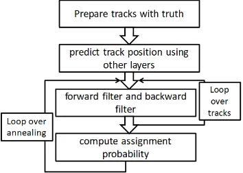
The flowchart of this algorithm is shown in Fig. 2. The flow of the algorithm contains the following points: 1) Prepare several candidate track seeds for each turn a track enters into the drift chamber. Take status (position, momentum, charge) of first hits from each turn (1st and 2nd turn only) from Monte-Carlo truth and form the seed tracks with smearing
of the momentum and position. 2) Find hits on road of candidate tracks and create track points including competition hits within certain range in detector space. The same hit can be assigned to more than one track point. And one hit can be shared by multiple candidate tracks. 3) Do Kalman filter iteratively with annealing scheme. The assignment probability for each hit is calculated from the residual of the distance to the track. Compute assignment probabilities between all tracks and all hits after the fitting of all the track candidates which tend to come from the same track. Hits close to each other are taken into account at the same time in the fitting by using their weighted mean. Several hits make contributions to one update of each track. One contribution of a hit can be shared by several candidate tracks. Hits from the wrong ambiguity, form the wrong turn or noise will be suppressed during iteration. 4) Repeat the iteration until the maximum annealing time is reached or the fits of all the tracks have converged with no further changes in 2 of fitting.
Fig. 2. Flow chart of fitting multi-turn track candidates
2.4 Preliminary performances
Samples with signal tracks without noise hits generated using Monte Carlo simulation are considered for this study. To validate the algorithm we use the single-turn track to do the fitting without competition between hits from different turns. The results are shown in Fig. 3. It shows for single-turn tracks, the momentum resolution is consistent with original GENFIT2. The result from the double-turn tracks shows similar resolution with the fitting when hits only from first turn are used. However, there exists a high momentum tail. The reason for the tail still needs to be investigated.
Fig. 3. Left histogram shows the momentum resolution for the single-turn tracks with multi-turn fitting algorithm. Right histogram shows the momentum resolution for the double-turn tracks with multi-turn fitting algorithm.
3 Summary and outlook
found to be promising. The method to pick the hits along the track road should be studied and the annealing scheme should be optimized.
References
1. COMET collaboration, COMET Phase-I Technical Design Report, arXiv:1812.09018 2. R. Frühwirth, NIMPRA 262 (1987) 444