International Journal of Research (IJR)
e-ISSN: 2348-6848, p- ISSN: 2348-795X Volume 2, Issue 11, November 2015Available at http://internationaljournalofresearch.org
Designing, Dynamic and Meshing Analysis of Planetary Gears
Assembly
1
L. Mohana Rao &
2Bhukya Swarnalatha
1. ASSISTANT PROFESSOR Bomma Institute of Technology and Science,Allipuram, Khammam, Telengana, INDIA - 507318
2. M.Tech, Bomma Institute of Technology and Science,Allipuram, Khammam, Telengana, INDIA – 507318
ABSTRACT:
A Machine consists of a power source and a power transmission system, which provides control
application of the power. Often transmission refers simply to the gear box that uses gears and gears
trains to provide speed and torque conversions from a rotating power source to another device The main
aim of our project is to focus on the mechanical design and analysis on assembly of gears in Planetarium
gear box. Analysis is also conducted by varying the materials for gears, i.e., Titanium Alloy and cast iron.
Presently used materials for gears and gear shafts are Cast Iron. In this project to replace the materials
with Titanium Alloy for reducing weight of the product decrease deformation and stress factor. Total
Model and Static analysis is completely analyzed by considering weight reduction in the gear box. The
design is done by using CATIA software. Modeling and assembly is done in CATIA. And following gear
design is imported in ANSYS and under static structure analysis, behavior of gears is studied.
INTRODUCTION
Planetary gear trains are one of the main
subdivisions of the simple epicyclic gear train
family. The epicyclical gear train family in general
has a central “sun” gear which meshes with and is
surrounded by planet gears. The outermost gear,
the ring gear, meshes with each of the planet
gears. The planet gears are held to a cage or carrier
that fixes the planets in orbit relative to each other.
Planetary gear is a widely used industrial product
in mid-level precision industry, such as printing
lathe,
automation
assembly,
semiconductor
equipment and automation system. Planetary
gearing could increase torque and reduce load
inertia while slowdown the speed. To compare
with traditional gearbox, planetary gear has
several advantages. One advantage is its unique
combination of both compactness and outstanding
power transmission efficiencies. A typical
International Journal of Research (IJR)
e-ISSN: 2348-6848, p- ISSN: 2348-795X Volume 2, Issue 11, November 2015Available at http://internationaljournalofresearch.org
Finally, we hope our product can be used in
industry in the future.
2.Planetary gear generation
By using SolidWorks software to build the 3D model of planetary gear, there are some things to do first, such as keeping a constant velocity ratio between two adjacent gear teeth, generating involute curve and set parameters of spur gear.
2.1 Constant Velocity Ratio
To get a constant velocity ratio, the common normal to the tooth profiles at the point of contact must always pass through a fixed point (the pitch point) on the line of centers. In figure 1, although the two profiles have different velocities at the contact point K, their velocities along N1N2 that is passing through the pitch point P are equal in both magnitude and direction. Otherwise the two tooth profiles would separate from each other. Therefore, we get the velocity ratio, which is equal to the inverse ratio of the diameters of these two tooth profiles. This is called fundamental law of gear-tooth action. For each two mating gearing tooth profiles, they should satisfy the fundamental law to get a constant velocity ratio.
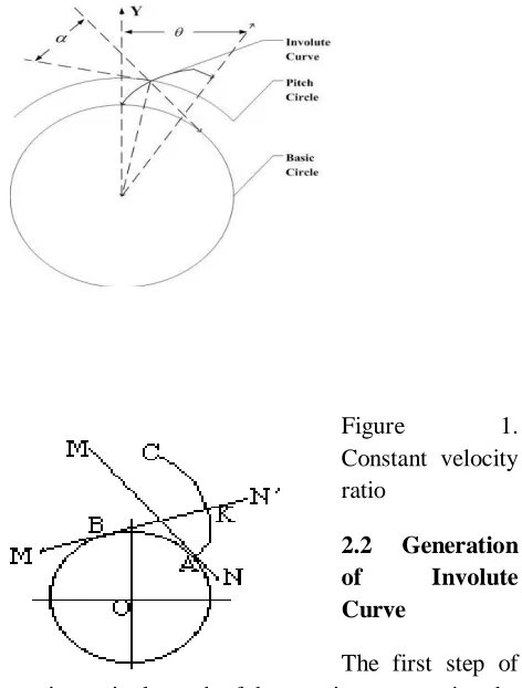
Figure 1. Constant velocity ratio
2.2 Generation
of Involute
Curve
The first step of generation a single tooth of the gear is to generating the involute curve. This involute curve is the path traced by a point on a line as the line rolls without slipping on the circumference of a circle. In Figure 2, let line MN roll in the counterclockwise direction on the circumference of a circle without slipping. When the line has reached the position M'N', its original point of tangent A has reached the position K, having traced the involute curve AK during the motion. As the motion continues, the point A will trace the involute curve AKC.
International Journal of Research (IJR)
e-ISSN: 2348-6848, p- ISSN: 2348-795X Volume 2, Issue 11, November 2015Available at http://internationaljournalofresearch.org
Usually we use the involute curve to generate a spur gear . The involute has important advantages -- it is easy to manufacture and the center distance between a pair of involute gears can be varied without changing the velocity ratio. Thus, we generate the involute curve to generate a spur gear
To generate a spur gear, some terminologies of the gear should be taken into consideration. The most important parameters in modeling we need to set the planetary gear are numbers of tooth, module, pitch circle diameter, pressure angle, basis circle diameter, addendum and dedendum. Figure 3 shows these terms. And Table 1 lists the standard tooth system for spur gears. circle and the dedendum circle to cut the two involute curves, and add the curve between them, extrude them to the certain width, then we have one tooth. Use the symmetry to arrange the tooth to the entire circle, and we have done with the gear model. The process of generating gears can be shown in Figure 4. Generating gears
2.5 Gears Generated
Based on the above method and parameter, we generated our planetary gear system, which contains one ring gear, two sun gears and four planet gears
3.The Gearbox design
The gearbox focused on, and used for model validation in this report is a 2 stage planetary gearbox made by Atlas Copco. The exploded view shows the components of the gearbox that will be explained in this chapter.
1. gear rim that functions as ring wheel
2. the planetary holder stage 2 complete assembly with planetary wheels
3. thin distance washer between stage 1 and 2
4. planetary holder stage 1 also acting sun wheel stage 2
5. needle bearing
6. planetary wheel stage 1
7. o-ring
8. thick washer or endplate stage 1
9. circlip to keep the thick washer in place
10. ingoing shaft from electric motor with sun wheel
The gearbox is made from hardened steel and has a gear ratio of 35 times in order to convert a high rotational speed into a large torque.
International Journal of Research (IJR)
e-ISSN: 2348-6848, p- ISSN: 2348-795X Volume 2, Issue 11, November 2015Available at http://internationaljournalofresearch.org
planetary holder (2) stage 2 which has 35 times lower rotational speed than the electric motor.
The thin washer (3) is used as a distance between the planetary holders stage 1 and 2. It has a smooth surface since the planetary holders has different speeds.
Theory of the gearbox and power losses
Epicyclic gear or more commonly named planetary gear is a form of gear setup typically used in applications where high gear ratio and/or small dimensions are sought after. There
are several different kinds of epicyclical gears available, the most common being the three and four wheel types. The gearbox in this thesis uses a three wheel design implementing three planetary gears in two stages. A three wheel design must however not use three planetary gears as three refer to the number of different sized wheels not the number of planetary wheels. A single stage can achieve a ratio of approximately ten, although sometimes an even higher ratio is required. In order to achieve this higher ratio two or more stages can be paired in an enclosure creating a gearbox with variable gear ratio and axis rotational direction.
The three wheel planetary gear stage consists of four parts.
1. Sun gear (center) S
2. Planetary gears (the three gears rotating around the Sun gear)
3. Planetary carrier (holds the planetary gears in place so the gear doesn’t jam) C
4. Ring wheel (the outer gear rim)
CONCLUSION
Designing Planet gear box is one of the difficult
task, major part of our project is done in CATIA
v5, which includes designing spur gears with
involute teeth with required dimensions and
assembly of messing gears Dynamic analysis is
done by using ANSYS on planet and sun gear
using different material, static analysis is done on
meshing assembly of sun and planet gears using
different material Now a days cast iron is widely
used for gears, we analyzed on titanium alloy, the
reason to chose these materials are high tensile
strength, low density and high frequency handling
properties we conclude that titanium alloy have
good properties when compared to present using
material (cast iron) Comparing to both material,
titanium alloy has both good static and dynamic
analysis features
REFERENCE
[1]
J. J. Uicker, G. R. Pennock and J. E.
Shigley, 2003, Theory of Machines and
Mechanisms, Oxford
University
Press,
New York.
[2]
B. Paul, 1979, Kinematics and Dynamics
of Planar Machinery, Prentice Hall.
[3]
Wright, M. T. (2007). "The Antikythera
Mechanism
reconsidered" (PDF).Interdisciplinary
science
reviews 32 (1).
Retrieved 20
May 2014.
[4]
JJ Coy, DP Townsend, EV Zaretsky,
International Journal of Research (IJR)
e-ISSN: 2348-6848, p- ISSN: 2348-795X Volume 2, Issue 11, November 2015Available at http://internationaljournalofresearch.org
[5]
Chad Randl, "Revolving architecture: a
history of buildings that rotate, swivel, and
pivot", p19
[6]
L. Meirovitch: Elements of Vibration
Analysis, McGraw-Hill, New York, 1986.
[7]
John M. Miller (May 2006). "Hybrid
electric
vehicle
propulsion
system
architectures of the e-CVT type". IEEE
Transactions on Power Electronics 21 (3):
756–767.doi:10.1109/TPEL.2006.872372.
[8]
P.
A.
Simionescu
(1998-09-01). "A
Unified Approach to the Assembly
Condition of Epicyclic Gears". ASME
Journal of Mechanical Design 120 (3):
448–453.doi:10.1115/1.2829172.
[9]
Lynwander, P., 1983, Gear Drive Systems:
Design and Application. Marcel Dekker,
New York
[10]
Smith, J. D., 1983, Gears and
Their Vibration: A Basic Approach to
Understanding
Gear
Noise.
Marcel
Dekker, New York and MacMillan,
London
[11]