Numerical simulation of fatigue failure of
composite materials under compression
Mark Petrov1, *
1Aeronautical research institute named after S. A. Chaplygin, Department of strength of materials and
structural components, 630051 Novosibirsk, Russia
Abstract. The process of fatigue fracture of carbon fibres reinforced
plastic under compressive loads is considered from the standpoint of the theory of reaction rates. Numerical simulation is based on rheological structural models of the material, which reproduce thermodynamic processes of local plastic deformation and failure occurring in time. The prediction of longevity of composite materials under compressive loads is similar to the solution of the problem for metal alloys under tensile loads when temperature and stresses are arbitrary functions of time.
1 Introduction
Fracture under variable loads, called fatigue, and the solution of the problem of assessing the longevity of materials under these conditions is a special case in the general problem of strength. Variable loads do not always lead to fatigue failure. Everything is determined by temperature and time loading conditions. But principles of fracture do not depend on how and under what conditions structures are loaded [1]. The composite material (CM) can be considered as a heterogeneous medium, which has same properties as any other material, but at the same time it is necessary to take into account peculiarities of its behaviour as a structure.
Considering various cases of failure of materials, we use instead of tens of various theories of creep, plasticity and fatigue one – the theory of reaction rates and one criterion of fracture – Bailey's criterion. It means the achievement of a threshold concentration of damages (microcracks, pores) in any volume of a solid body, which translates the failure process to the next dimensional level [2]. W. Kauzmann was the first to apply the theory of reaction rates to the flow of solids [3].
For example, by solving the same differential creep equation for different loading cases, it is possible to obtain many "plasticity theories" that take into account in each material peculiarity of its structural heterogeneity and its changes during the flow. Prediction of fracture as a thermodynamic process is based on a mathematic description of local micro-plastic strains and the general flow of the material occurring in time and its accompanying. This is an alternative approach that eliminates the conditionality and incompatibility of existing ones.
Failure at variable compressive loads in metal alloys is a damped process, but creates damages that reduce the longevity under tensile loads. Fracture from tensile loads with simultaneous action of both is faster compared to the accumulation of damage from compressive. Therefore, compression damages can be neglected.
In CM it is the opposite. Fibers cannot work in compression, and only the binder forces them to bear some kind of load, but much less than they can withstand during tension. Therefore, it is proposed to use a similar approach, assuming that compressive loads in CM lead to the same as tensile loads in metals. A tensile stresses with a predominance of compressive can also be neglected. The solution of the problem is based on the same principle, which connects the rate of inelastic deformation of the material with the rate of failure that have the same connection at fracture as a result of creep. Similar mathematical models were previously used, but they were built on a purely mechanical representation about the mechanisms of internal friction [4].
Thus, it is required to model the structural heterogeneity of the material, which is quantitatively expressed by the field of internal stresses that occur during loading, and the distribution of fracture and flow processes over the volume of the material in accordance with its structural heterogeneity.
2 Experimental results
As is required in the study of properties of any material, carbon fibre reinforced plastic were first tested for compression at different temperatures and loading speeds. According to test results, the initial activation energy of the failure process was determined.
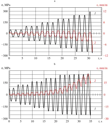
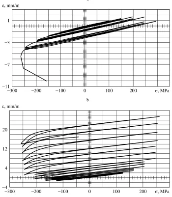
A feature of the behaviour of CM is individual deformation properties of each specimen with the same scheme of laying differently oriented layers. Figure 1 shows diagnostic results of two identical specimens loaded by a symmetrical cycle with stepwise increasing amplitude, and figure 2 shows characteristics of their inelastic behaviour. The final fracture of both specimens occurred from compression at almost same stress values, and residual strains at the same time had opposite signs. The probable reason for this is a different initial stretch of fibres in the manufacture. In the last half-cycle of compression, the increment of the longitudinal strain of 2nd specimen already corresponded to the direction of stress action.
The first specimen demonstrated "classical" behaviour. Each stage of loading consisted of three equal in amplitude cycles, and each transition to the next stage gave a significant increase in inelastic strain, which decreased in subsequent cycles. The strain grew in the direction of compression. Having sustained at the next stage of the stress +293 MPa, worked out by the test machine, the specimen was fractured, reaching a maximum stress of only −264.1 MPa.
The second specimen was deformed with the increase of positive residual strains. On the last step of loading, after the stress maximum +261.6 MPa, the increase of strains in the direction of stretching is reduced, and in the half-cycle of compression he collapsed after the maximum stress value −257.2 MPa. That is, test results are almost identical with fundamentally different deformation properties of specimens. Note that the final fracture of specimens occurs, as a rule, at the stage of unloading, since the residence time at maximum cycle stresses is small.
a
0 5 10 15 20 25 30
−300 −150 0 150 300
−12 −6 0 6 12 σ, MPa
1
t, s ε, mm/m
2
b
0 5 10 15 20 25 30 35
−300 −150 0 150
−30 −15 0 15 σ, MPa
1
t, s ε, mm/m
2
Fig. 1. Loading of specimen 1 (a) and specimen 2 (b): 1 – change in stress over time, 2 – change in longitudinal strain.
An increase in the average rate of inelastic deformation equal to the increment of the inelastic hinge opening due to the plastic hysteresis h to the average value of the cycle
a
−300 −200 −100 0 100 200
−11 −7 −3 1 ε, mm/m
σ, MPa
b
−300 −200 −100 0 100 200
−4 4 12 20 ε, mm/m
σ, MPa
Fig. 2. Inelasticity of specimen 1 (a) and specimen 2 (b) at step increase of loading amplitude.
In the study of fatigue life of metal alloys, a mathematical model for predicting fatigue failure was constructed using the relationship of deformation and fracture processes. This relationship is similar to that observed in failure under constant stress. When the structure of the material does not undergo significant changes, the longevity is inversely proportional to the rate of steady-state creep [2].
10−5 10−4 10−3 10
103 τ, s
ΔεhN/τ, s−1
1
2 3
4
Fig. 3. Statistics of connection of inelasticity and longevity of specimens from carbon fiber reinforced plastic Torayca T700 with different reinforcement schemes : 1, 2 – eight-layer unidirectional composite, 3 – the same composite with the addition of seven intermediate layers with perpendicular and diagonal stacking.
0 20 40 60 80 100
−0.1 0.2 0.5 0.8 dS, mm
Pa, kN
1 2 3
Pa0
4
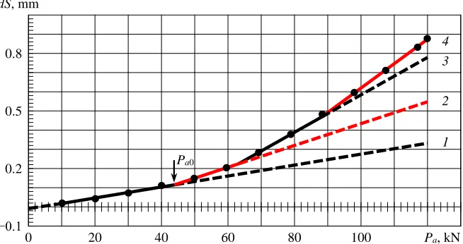
Fig. 4. Amplitude dependence of the disclosure of the inelasticity loop of one of specimens from carbon fiber reinforced plastic Torayca T700 with orthogonal laying: 1 – relaxation type inelasticity,
2-4 – addition of inelasticity loop disclosure due to the appearance of local plastic strains appearing in different places of the material structure.
Inelastic strain dS was calculated according to the displacement of the stroke relative to the length of the working part of the specimen of 287 mm, which was enshrined in hydraulic grips of the test machine MTS-50. There are no plastic deformations in the structure of the material at the initial stage of loading up to the amplitude of Pa0 (line 1, coming out of the beginning of the coordinates and extrapolated to the amplitude of 120 kN by the dashed line), and inelastic deformation is associated with local viscous currents in the material. The strain at these amplitudes only lags behind the stress phase. Fatigue fracture in this region of amplitudes is usually not observed. Only point defects that cannot be detected by anything can lead to failure after a very long time of operation [2].
3 Numerical simulation of failure process
Mathematical model for carbon fiber reinforced plastic Torayca T800, which had half longitudinally oriented layers, was built on the basis of experimental data for symmetrical loading cycle. As a connection between deformation and failure, the one that should be with the identity of the composite manufacturing technology (as shown in figure 2a) was adopted. The amplitude dependence of the damage per cycle (1/N) for these specimens is shown in figure 5. It has two characteristic areas. Under monotonic compression loading, the failure of specimens under study occurs on average at stresses equal to −360 MPa (at tensile load stresses equal to 1,083.4 MPa). The amplitude a0 303 MPa corresponds to the "fatigue limit" for the symmetric loading cycle – a conventional value, the limit is not essentially, since it depends on loading conditions and temperature [2].
300 305 310 315 320 325 330 335 340 345
−0.0002 0.0004 0.0010 0.0016 1/N, cycle−1
σa, MPa
1 2
Fig. 5. The amplitude dependence of the damage per cycle of specimens from carbon fiber reinforced plastic Torayca T800: 1 – for the failure probability of 0.5, 2 – for the failure probability of 0.0228.
Further, using the relationship of damage during the loading cycle with the disclosure of the plastic hysteresis loop, the parametric identification of the material model with the corresponding change in the sign of stresses and strains was carried out. This made it possible to use the same software that was developed for metal materials [2].
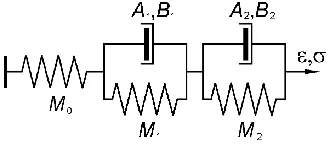
Fig. 6. Rheological model of a solid body with two elements plastic flow (M0 is the elastic modulus
of Hooke's body).
1 0 1ln exp[ ( 0 0 )] [1 exp( BDt)] D AM Dt M B B Dt M
.
At D = 0 it takes the form:
B M ABMt
B
M ln exp[ ( )]
1 1
0 0
0
.
In these solutions A0exp[Q0/(RT)] and B/(RT)
,
where R is the universal gas constant and the product 0, the initial activation energy Q0 and the activation volume are determined by the parametric identification of the model by the amplitude dependence of the inelasticity associated with damage during the loading cycle. Since the absolute temperature T is included in equations explicitly, these solutions allow us to numerically reproduce any arbitrary temperature-force loading process in the form of a piecewise linear dependence.In the product 0 (0 is characteristic Debye’s frequency [1]) is the deformation contribution, depending on the stress, and hence the asymmetry of loading. To take into account the asymmetry of loading, necessary data were not available, so parameters of structural elements of the material model had constant values.
a b
102 104 106
10 10 10 2 4 6 Ne, cycle
Nc, cycle
1 2
3 4
102 103 104 105 10 10 10 2 4 6 Ne, cycle
Nc, cycle
1 2
3 4
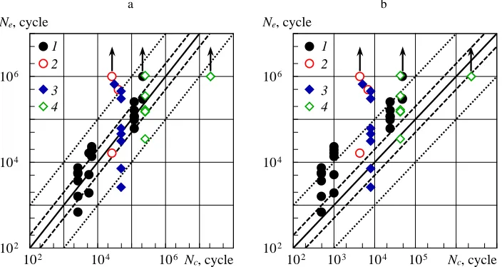
Fig. 7. Comparison of calculated Nc and experimental Ne endurance values of Torayca T800 carbon
fiber reinforced plastic specimens for fracture probability of 0.5 (a) and 0.0228 (b); m, MPa: 1 – 0
(a = 0), 2 – −50 (a = −0.177 and −0.231), 3 – −110 (a = −0.419 and −0.493), 4 – −166.5 (a = −1 and −1.129).
Verification calculations of longevity for those loading modes for which parametric identification of the model was carried out were performed. Summation of damages was carried out on structural elements of the material model independently. Then, all other modes of asymmetric loading were calculated in time for each frequency (3 and 5 Hz) at which tests were carried out. Figure 7 shows a comparison of the calculation and experimental data. The actual scatter in the experiment is shown. The endurance of specimens without fracture is marked by arrows. Only one mode with a large value of the asymmetry (the ratio of the mean stress of the cycle to the amplitude a = m/a = −1.947)
material model that take into account the loading asymmetry, calculations correctly reflect the dependence of endurance on mean stresses of the cycle and the loading amplitude up to a = −1. The main part of results falls into a two-fold corridor of deviations from their calculated estimates obtained for the probability of failure of 0.5, and for the probability of failure of 0.0228 is located on the lower boundary of the scatter.
If it is necessary to fulfil required conditions of safe operation of structures, calculations are usually carried out according to data for a given probability of failure. In figure 5, this corresponds to the fact that results of the experiment from mean logarithmic values of endurance are subtracted, for example, two mean square deviations. And according to data indicated by the piecewise linear dependence 2, the repeated parametric identification of the material model is made. If necessary, it is possible to calculate the "fatigue limit" for each load asymmetry.
Calculations were performed by time steps, and then recalculated into the number of cycles. We also made estimates of the longevity under program loading, which usually replace the real process, distorting its spectral composition. They were then converted into blocks of loading, which demonstrates the principle of the development of equivalent programs of structure testing, taking into account the temporary nature of the process of fatigue fracture. The "equivalence" of loading calculated by existing methods based on the "ideology of the cycle", as it turned out, leads to obvious errors.
4 Conclusions
So, the sequence of actions in the construction of the structural model of the material should be as follows. The first step is to obtain the amplitude dependence of inelasticity, for example, in a symmetric loading cycle. Further, in each plot of the increase in the disclosure of the loop of inelasticity are selected two loading amplitudes. Then longevity tests are carried out at any loading frequency at two values of mean cycle stresses for each of loading amplitude. And, finally, parameter identification of material model performs, with data for inelasticity. The test temperature and the frequency at each loading mode may differ, therefore, must be recorded, as taken into account in the processing of experimental data.
In the case of the predominance of tensile loads, the problem of simulation the fracture process of CM is similar to that solved for metal alloys, and is based on identical dependencies linking the inelastic behaviour of the material with the accumulation of damage in it [2]. In numerical simulations of thermodynamic deformation and fracture processes occurring within a material, no defining relationships used in solid mechanics are required. Applied calculation procedures were tested according to standard realizations of Society of Automotive Engineers [8] and according to own experiments [2]. They showed the same quite satisfactory result for CM at compressive loads.
References
1. V. A. Petrov, A. Y. Bashkarev, V. I. Vettegren, The physical basis of prediction of longevity of structural materials (Polytechnics, S. Petersburg, 1993)
2. M. G. Petrov, Strength and longevity of structural components: an approach based on models of material as a physical medium (LAP, Saarbrücken, 2015)
5. L. N. Stepanova, M. G. Petrov, V. V. Chernova, et al., Deform. Mat. Fract., 5, 37 (2016)
6. L. N. Stepanova, M. G. Petrov, V. V. Chernova, Monit. Diagn., 8, 18 (2017) 7. M. G. Petrov, J. Appl. Mech. Tech. Phys. 39, 104 (1998)