LASER HARP
Manas Dawda
1, Shraddha Kadam
2, Sushrut K
3,
Neha Raina
4, Pravin Annadate
51,2,3,4
BE Electronics,
5Assistant Professor, Department of Electronics,Vidyalankar Institute of Engineering, Mumbai University (India)
ABSTRACT
Modern time calls for innovation and thinking outside the box. As the name suggests, here we have LASERs
replacing the conventional strings in a harp. Instead of plucking the strings one just needs to place hands in the
path of beams. Different lasers are used for different notes and every laser creates multiple pitches depending
upon the position of the hand. Various tones could be created by hitting proper chords as every point is
intercepted differently. Here we have a perfectly calibrated harp. The lasers are just for visually guiding the
user and act as visual strings. The main purpose of strings is served by photo diodes and proximity sensors.
Different set of diodes and sensors act as individual strings which are calibrated to produce different notes. On
single set the proximity sensor act as frets producing unique pitch at unique location. AT mega is programmed
to give desired output. Tuning is adjusted in the program itself. For this project we are using AT mega 16, photo
diodes, laser transmitters, LCD.
Keywords: ATMEGA16, Lasers, Photo Diodes, LCD Display, Speaker with Amplifier, Music
Instrument
I. INTRODUCTION
The Laser Harp is an electronic harp using laser beams instead of conventional strings. The user will be able to
play notes by breaking the beams with his/her hands. The Laser Harp is a new musical instrument where notes
are selected and played by breaking the beams of 7 separate lasers, representing each of the major and minor
notes in a musical octave. The harp itself is rectangular in shape, approximately 3 feet wide and 4 feet tall, with
7 parallel 532nm (red) laser beams pointing vertically spaced evenly across it, each pointed towards a
phototransistor. When the user breaks a beam (by placing their hand in it), the corresponding note is played out
through external speakers. The harp also determines the vertical height of the user’s hand along the harp, and the
tone of the played note is modulated accordingly. Each phototransistor circuit is fed into a microprocessor,
which detects which string has been broken, and thus which note must be played.
II. INITIAL USAGE SCENARIO
The Laser Harp is meant to be commercialized as a musical toy. The design of the harp will be as simple as
possible, thus will come with little instructions. We envisioned one ON/OFF button and 3 teacher toggle
buttons, one for each preset song. The Laser Harp would have an automatic power-off function. To operate the
unit, the user would break the beams with any object, most likely their fingers; as soon as the beam is broken,
the appropriate note will be played, through a built-in speaker. A user could use the instrument as an educational
tool, taking advantage of the teaching mode feature in order to learn and play simple songs. By pressing a
button, the teaching mode would be activated. While in teaching mode, the Laser Harp would teach a preset
melody by turning off lasers, one note at a time, allowing the child to see what note to play and in what order.
III.
DEVELOPMENT
STAGES
&
PROCESS
The complete development of this system can be divided into the following stages:
Problem definition stage; Designing block diagram;
Implementing circuits and components; Developing algorithm for software; Writing actual code for Microcontroller; Compiling the code;
Burning the hex file into microcontroller with programmer Testing and Running.
IV.
OVERVIEW
OF
THE
BUILDING
BLOCKS.
4.1 Photo Transistor
Fig2. Photo Transistor and Corresponding Circuit
A Photodiode is a p-n junction or p-i-n structure. When an infrared photon of sufficient energy strikes the diode,
it excites an electron thereby creating a mobile electron and a positively charged electron hole. If the absorption
occurs in the junction's depletion region, or one diffusion length away from it, these carriers are swept from the
junction by the built-in field of the depletion region, producing a photocurrent. Photodiodes can be used under
either zero bias (photovoltaic mode) or reverse bias (photoconductive mode). Reverse bias induces only little
widening of the depletion layer (therefore expanding the reaction volume) and strengthening the photocurrent
when infrared falls on it.
4.2 Laser
Fig3. Laser diode
A laser (light amplification by stimulated emission of radiation) is a device which uses a quantum mechanical
effect, stimulated emission, to generate a coherent beam of light from a lasing medium of controlled purity, size,
and shape. The output of a laser may be a continuous, constant-amplitude output (known as CW or continuous
wave), or pulsed, by using the techniques of Q-switching, model locking, or gain-switching. In pulsed operation,
much higher peak powers can be achieved. A laser medium can also function as an optical amplifier
when seeded with light from another source. The amplified signal can be very similar to the input signal in
terms of wavelength, phase, and polarisation; this is particularly important in optical communications. The verb
"to lase" means to give off coherent light or possibly to cut or otherwise treat with coherent light, and is a
back-formation of the term laser.
4.3 Atmega 16
Now the key component is the ATMEGA16 AVR microcontroller.The ATmega16 is a low-power CMOS 8-bit
microcontroller based on the AVR enhancedRISC architecture. By executing powerful instructions in a single
clock cycle, theATmega16 achieves throughputs approaching 1 MIPS per MHz allowing the system designer to
optimize power consumption versus processing speed.
4.4 LM7805 Series Voltage Regulators
A voltage regulator is an electricalregulator designed to automatically maintain a constant voltage level. It may
use an electromechanical mechanism, or passive or active electronic components. Depending on the design, it
may be used to regulate one or more AC or DC voltages. With the exception of shunt regulators, all voltage
regulators operate by comparing the actual output voltage to some internal fixed reference voltage. Any
difference is amplified and used to control the regulation element. This forms a negative feedbackservo control
loop. If the output voltage is too low, the regulation element is commanded to produce a higher voltage. If the
output voltage is too high, the regulation element is commanded to produce a lower voltage. In this way, the
output voltage is held roughly constant
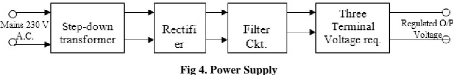
V. POWER SUPPLY DESIGN
Power supply is the first and the most important part of our project. For our project we require +5V regulated
power supply with maximum current rating 500Ma.
Fig 4. Power Supply
5.1 Step Down Transformer
Step down transformer is the first part of regulated power supply. To step down the mains 230V A.C. we require
step down transformer. Following are the main characteristic of electronic transformer.
1) Power transformers are usually designed to operate from source of low impedance at a single freq.
2) It is required to construct with sufficient insulation of necessary dielectric strength.
3) Transformer ratings are expressed in volt–amp. The volt-amp of each secondary winding or windings are
added for the total secondary VA. To this are added the load losses.
4) Temperature rise of a transformer is decided on two well-known factors i.e. losses on transformer and heat
dissipating or cooling facility provided unit.
5.2 Rectifier Unit
Rectifier unit is a circuit which converts A.C. into pulsating D.C. Generally semi-conducting diode is used as
rectifying element due to its property of conducting current in one direction only. Generally there are two types
of rectifier.
1) Half wave rectifier
2) Full wave rectifier.
In half wave rectifier only half cycle of mains A.C. is rectified so its efficiency is very poor. So we use full wave
bridge type rectifier, in which four diodes are used. In each half cycle, two diodes conduct at a time and we get
maximum efficiency at o/p.
Following are the main advantages and disadvantages of a full-wave bridge type rectifier circuit.
Advantages:
1) The need of center tapped transformer is eliminated.
2) The o/p is twice that of center tap circuit for the same secondary voltage.
3) The PIV rating of diode is half of the center tap circuit.
Disadvantages:
1) It requires four diodes.
2) As during each half cycle of A.C. input, two diodes are conducting therefore voltage drop in internal
resistance of rectifying unit will be twice as compared to center tap circuit.
5.3 Filter Circuit
Generally a rectifier is required to produce pure D.C. supply for using at various places in the electronic circuit.
However, the o/p of rectifier has pulsating character i.e. if such a D.C. is applied to electronic circuit it will
produce a hum i.e. it will contain A.C. and D.C. components. The A.C. components are undesirable and must be
kept away from the load. To do so a filter circuit is used which removes (or filters out) the A.C. components
reaching the load. Obviously a filter circuit is installed between rectifier and voltage regulator. In our project we
use capacitor filter because of its low cost, small size and little weight and good characteristic. Capacitors are
VI. SOFTWARE DEVELOPMENT
The model used is Classic Life Cycle Model
The Project team is meeting once a week to discuss the progress made by each member and to share the
relevant information and be documents that have been prepared. The number of meetings may increase
during the final semester as the team members will have more time.
There are reviews being conducted once a week during the team meetings. A complete technical review
will be conducted at the end of the Design Phase. There will be reviews conducted at the completion of
every testing phase.
The major milestones to be achieved are as follows:
1. Results of research of existing system and discussions with the Project leader.
2. Results of interview with experts and team meetings to finalize the requirements of the software.
3. Results of the Design Phase, which include a number of modeling diagrams, like the use cases, class
diagrams, etc.
4. Results of the first coding phase will be an initial code that will be then tested.
Based on the results of the testing, the code will be reviewed in the second coding phase.
VII. RESULT
Fig5. Laser Harp
VIII. CONCLUSION
In this project, the design and implementation of a new kind of electronic musical instrument has been explored.
From the results, it is evident that this kind of device is both practical and relatively inexpensive to construct and
operate. We successfully implemented the requirements we set out to achieve. The fundamentals of this system
are formed, but the overall design, precision and effectiveness can be improved. With further adaptions and
improved methods, the possibilities of this device are endless. It opens up a whole new area to the electronic
musical industry.
REFERENCES
[1] Lasers - http://howthingswork.virginia.edu/lasers.html
[2] All data sheet - Datasheet search site for Electronic Components http://www.alldatasheet.com/
[3] http://www.epemag.wimborne.co.uk/