Implementing Business Process Recovery Patterns
through QVT Transformations
Ricardo Pérez-Castillo, Ignacio García-Rodríguez de Guzmán and Mario Piattini Alarcos Research Group, University of Castilla-La Mancha
Paseo de la Universidad, 4 13071, Ciudad Real, Spain {ricardo.pdelcastillo, ignacio.grodriguez, mario.piattini}@uclm.es Abstract. Traditionally, software maintenance takes only technical information into account to evolve legacy systems. However, business knowledge, which could help to improve the comprehension of legacy systems, is rarely recovered. Probably, that knowledge is not considered due to the fact that business knowledge recovery is a problem with a non trivial solution. This paper contributes to the solution of this problem through the use of a set of patterns and the implementation through QVT transformations, which takes KDM (Knowledge Discovery Metamodel) models concerning the system and obtains BPMN (Business Processes Model and Notation) models to represent the embedded business knowledge. A case study reports that the transformation obtains cohesive and loosely-coupling business processes diagrams; and it is scalable to large systems. As a consequence, the business processes recovery can enhance the maintenance since they provide the business concept location in legacy systems, among other improvements.
Keywords: Maintenance, legacy system, KDM, business process, case study.
1 Introduction
Software is an intangible thing that ages in similar way to any material object, thus it must be maintained, which can produce more ageing. This is known in software engineering as software erosion problem [23]. The difference between software and material things is that software cannot be replaced from scratch, since (i) the entire replacement of an information system is very expensive, which (ii) also stops the achievement of ROI (Return Of Investment) [21]; and finally (iii) the software embeds a lot of business knowledge over time that would be lost if it is replaced [15].
In order to deal with software erosion problem, the evolutionary maintenance is the most appropriate kind of maintenance because it preserves the legacy business knowledge and makes it possible to evolve the systems with an acceptable budget [19]. Nowadays, the software modernization, and specifically the Architecture-Driven Modernization (ADM) proposed by the Object Management Group (OMG) [11], became one of the most successful practice for carrying out evolutionary maintenance. ADM is based on traditional reengineering process but it treats the involved software artifacts as models and establishes model transformations between them according to the Model-Driven Architecture (MDA) principles. In addition, the OMG has defined Knowledge Discovery Metamodel (KDM) [14] together with ADM. KDM allows ADM-based processes to represent as models all the different artifacts involved in a legacy system such as source code, databases, user interfaces.
The reverse engineering stage of any ADM-based process obtains the models that represent the legacy system. The reverse engineering stage can reach three different abstraction levels, which lead to three kinds of ADM-based processes [9]: (i) technical level, which is related to migration to another language, where a physical model of the systems is obtained; (ii) application/data architecture level, which focuses on obtaining a model of the system design at intermediate abstraction level; and (iii) business level, which increases the degree of abstraction since a business architecture model is obtained.
The first and second levels have been addressed in traditional maintenance processes for many years in order to recover technical information about how the computation is done. However, besides that technical information there is a lot of business knowledge like concepts from the business domains and their relations, business rules and constraints, etc. that is rarely recovered to maintain legacy systems reaching the third level. When modernization process reaches the business level, the additional business knowledge helps to comprehend and maintain the system as well as to locate the business logics in the source code and other software artifacts [3].
Recovery business knowledge from legacy systems is a challenge that is addressed frequently in literature but it is still a latent problem since its solution is not trivial. This paper shows MARBLE [16], an ADM-based framework to obtain business knowledge, through a set of business processes, embedded in legacy information systems. MARBLE uses the KDM metamodel to represent a model of the legacy system, and the BPMN (Business Processes Model and Notation) metamodel to represent a business process model. This paper proposes, within MARBLE, a declarative model transformation in order to transform KDM models into BPMN models. The proposed transformation is based on a set of business patterns [17], thus it is implemented in declarative way. The transformation is implemented by means of QVT-Relations, the declarative language of QVT (Query/View/Transformation) [13].
In addition, this paper presents a case study that involves a CRM (Customer Relationship Management) system, which was used to apply the proposed transformation. The case study reports that the transformation is efficient and enables to obtain business process models with specific quality characteristics. The case study is conducted according to the case study protocol proposed by Brereton el al. [2] in order to ensure the greatest rigor and validity of the case study.
The remainder of this paper is organized as follows. Section 2 summarizes the background of business process as well as ADM and KDM standard. Section 3 presents MARBLE, the framework where the proposed transformation is applied. Section 4 presents the proposed declarative model transformation in detail. Section 5 reports the case study conducting to validate the proposal. Section 6 shows the work related to business knowledge recovery. Finally, Section 7 draws the conclusions of this paper.
2 Background
This section presents the background of this paper: firstly, it shows the business process concept; secondly, it introduces ADM and KDM standard.
2.1 Business Process
A business process is a sequence of coordinated activities performed in an organizational environment, which aims at a certain business goal [24]. Interest inside organizations in knowing their business processes has increased because they consider them to be a key asset (i) for their performance since the business processes depict the operations of the organization; (ii) in order to improve their competitiveness, because the business processes can be adapted in order to increase customer satisfaction, reduce costs, distinguish products or services, and so on; and finally, (iii) understanding business processes is an important step for the comprehension and maintenance of the source code, and in general of the information systems.
In order to achieve optimal business process management, it is necessary to represent explicitly the business processes by means of a notation understandable by the different roles involved in its management [8]. The most important notations are the Activity Diagrams of UML 2.0 and the Business Processes Model and Notation (BPMN) [12]. The Business Process Diagram (BPD) of BPMN is the notation used in this work since it is a well-known graphical notation and is easily understood by both system and business analysts.
2.2 ADM & KDM
ADM is the mechanism proposed by OMG to deal with software modernization. ADM is a process for understanding and evolving existing software assets in order to restore the value of existing applications. ADM provides several benefits such as ROI improvement on existing information systems, reducing development and maintenance costs, extending the life cycle of legacy systems and easy integration with other systems [11].
ADM is the concept of modernizing existing systems with a focus on all aspects of the current system architecture and the ability to transform current architectures to target architectures [11]. For this purpose, ADM advocates carrying out reengineering processes that treat any involved artifact as a model at specific abstraction level. Moreover, ADM makes it possible to refine models throughout different abstraction levels transforming the models by means of deterministic model transformations.
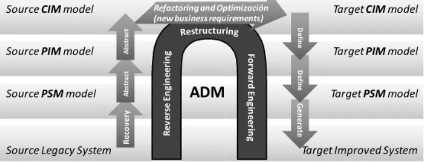
Fig. 1. Horseshoe modernization model
The horseshoe reengineering model has been adapted to ADM and it is known as the horseshoe modernization model [9] (see Fig. 1). The model consists of three
Target Improved System Target PSMmodel Target PIMmodel Target CIMmodel
Source Legacy System Source PSMmodel Source PIMmodel
Source CIMmodel Refactoring and Optimización (new business requirements)
R e v e rs e E n g in e e ri n g Fo rw a rd E n g in e e rin g
ADM
G e n e ra te D e fin e D e fin e R e co v e ry A b st ra ct A b st ra ctstages: (i) reverse engineering identifies the components of the system and their interrelationships, and it builds one or more abstract representations of the legacy system; (ii) restructuring transforms the abstract representation into another system representation at the same abstraction level, which improves the source legacy system but preserving the external behavior of the system; finally (iii) forward engineering generates physical implementations of the target system at a low abstraction level.
In addition, the horseshoe modernization model uses MDA nomenclature to refer to different abstraction levels (see Fig. 1): (i) CIM (Computation Independent Model) is a business view of the system from the computation independent viewpoint at a high abstraction level; (ii) (PIM) Platform Independent Model is a view of a system from the platform independent viewpoint at an intermediate abstraction level, thus a PIM models abstract all implementation details related to the platform; and finally (iii) PSM (Platform Specific Model) is a technological view of a system from the platform specific viewpoint at a low abstraction level.
Moreover, ADM spearheads the definition of several standards related to software modernization. KDM is the cornerstone within this set of standards and has been recognized as standard ISO 19506 [6]. KDM provides a metamodel to represent and exchange information about software artifacts in legacy systems. KDM enables the representation, at different abstraction levels, of all software artifacts like source code, user interfaces, database, business rules, and so on.
KDM can be compared with the Unified Modeling Language (UML) standard; while UML is used to generate new code in a top-down manner, the ADM processes involving KDM start from the existing code and build a higher level model in a
bottom-up manner [10]. Despite this fact, KDM is not only used in reverse engineering stage. It is also used in restructuring and forward engineering stages since provides a common knowledge repository for the whole modernization process.
3. MARBLE
MARBLE (Modernization Approach for Recovering Business Processes from Legacy Systems) is an ADM-based framework for recovering business processes [16]. MARBLE focuses on the reverse engineering stage of the horseshoe modernization model to rebuild the business process embedded in legacy systems. MARBLE defines four abstraction levels (from L0 to L3) that represent four different kinds of models as well as three model transformations between the levels (see Fig. 2).
Firstly, the L0 level represents the legacy information system in the real world as a set of physical artifacts, that is: source code, databases, documentation and so on. Secondly, the L1 level represents a set of PSM models that can depict all the different software artifacts at L0 level according to different metamodels. For instance, a code model according to a Java metamodel, a user interface model according to a UIDL (User Interface Description Language) metamodel, a database model according to the SQL (Structure Query Language) metamodel, and so on. Thirdly, the L2 level integrates all knowledge about legacy software artifacts in a single PIM model represented in standardized way by means of the KDM metamodel. Finally, the L3 level represents the target model of the framework, a business model that represents the underlying business processes embedded in the legacy system. The business model is modeled according to the BPMN metamodel
Fig. 2. MARBLE overview
L0-to-L1 transformation. This transformation analyzes the legacy software artifacts at L0 level and build the PSM models according to the specific metamodels. The analysis can be done by means of different reverse engineering techniques like static analysis which examines the source code files, the dynamic analysis which analyzes the source code in run time, the program slicing that studies the code dividing it into different fragments, among other techniques. Currently, MARBLE supports static analysis of source code of Java-based legacy systems.
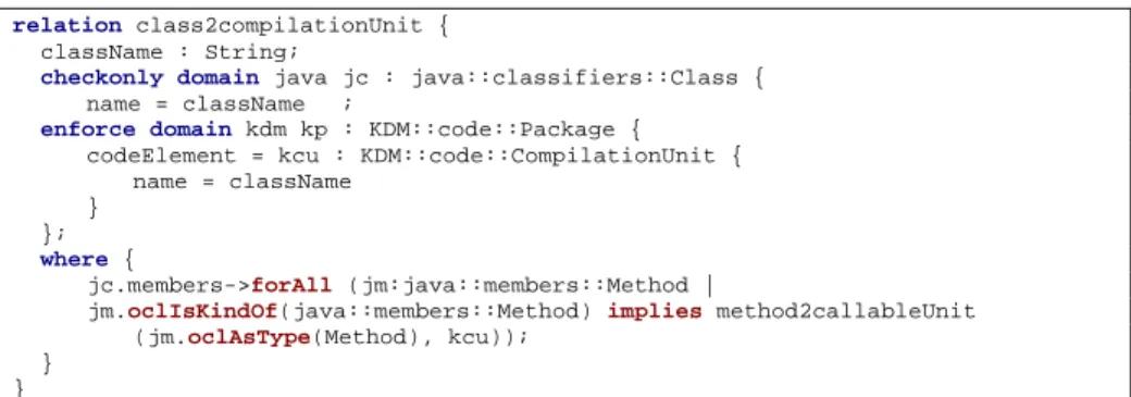
L1-to-L2 transformation. In order to obtain a KDM model, this transformation consists of a model transformation implemented in QVT-Relation. The transformation defines a set of declarative relations to transform instances of meta-classes related to different software artifacts into more abstract elements according to the KDM metamodel. Fig. 3 shows as example a QVT relation within the L1-to-L2 transformation. This relation transforms all instances of the Class meta-class in the Java code model (L1) into instances of CompilationUnit, a more generic meta-class of the KDM model (L2). The relation also examines instances of the Method meta-class that belong to the Class meta-class in order to the method2CallableUnit relation be also triggered.
relation class2compilationUnit { className : String;
checkonly domain java jc : java::classifiers::Class { name = className ;
enforce domain kdm kp : KDM::code::Package { codeElement = kcu : KDM::code::CompilationUnit { name = className
} };
where {
jc.members->forAll (jm:java::members::Method |
jm.oclIsKindOf(java::members::Method) implies method2callableUnit (jm.oclAsType(Method), kcu));
} }
Fig. 3. Example of QVT relation to transform Java code models into KDM models
MARBLE L2. KDM Model
L0. LIS
L1. LIS Models L3. BP ModelReverse engineering techniques applied to different LIS artefacts: static/dinamic analysis, slicing, and so on QVT transformations PSM to PIM
QVT transformations based on pattern matching Business expert refinement
L2-to-L3 transformation. The last transformation of MARBLE has a hybrid nature, since it consists of a model transformation as well as a manual transformation by business experts. Firstly, the model transformation obtains a BPMN model (L3) from the KDM model (L2) according to a set of business patterns that is implemented by means of QVT-Relation. The obtained business process models are preliminary since many of the recovered business process elements are business-independent, which including most of the utilities, input/output, and other auxiliary code. Secondly, manual interventions are done by the business experts in order to refine the preliminary business processes. Business experts could add or remove new business elements in a business process model; join or split a business process model; or even, they could discard a whole model. The next section presents the main contribution of this paper in detail: the declarative model transformation.
4 KDM-to-BPM/ Transformation
The KDM-to-BPMN transformation is a model transformation which is part of the L2-to-L3 transformation of MARBLE. The model transformation takes, as input, a KDM code model and produces, as output, a business process model according to the BPMN metamodel. Basically, the transformation carries out a business pattern matching that is implemented using the QVT-Relation language.
Firstly, this section explain briefly the metamodels used in both kinds of models, the input and output model. Secondly, it presents the set of patterns, which is used to carry out the pattern matching through the model transformation. Finally, it shows the most important implementation details of the model transformation using QVT.
4.1 Involved metamodels
The KDM metamodel is divided into several packages organized in different abstraction layers. The transformation takes a KDM model that considers only the
code and action packages at the program element layer of KDM. The code package enables the representation of code elements of legacy systems and their associations in a technological-independent manner. The action package extends the code package to represent behavior descriptions and control- and data-flow relationships between code elements. Fig. 4 shows the KDM metamodel concerning code and action
packages. A legacy system is represented as a CodeModel element, the root meta-class. A CodeModel is composed of AbstractCodeElements, a meta-class that represents an abstract class for all KDM entities that can be used as CallableUnit,
StorableUnit, etc. The CodeElements are also interrelated by means of AbstractCode-Relationships, a meta-class to represent an abstract class for all KDM relationships that can be used to represent the code such as Flow, Calls, Reads, Writes.
The BPMN metamodel is used to represent the target models obtained after the model transformation. Fig. 5 presents the BPMN metamodel, which enables the representation of business process diagrams. A business process diagram involves four kinds of meta-classes: (i) flow object classes such as Events, Activities and
Gateways; (ii) connecting object classes like SequenceFlows, MessageFlows and
Associations; (iii) artifact classes such as DataObjects, Groups and Annotations; and (iv) swimlane classes for grouping other elements such as Pools and Lanes.
Fig. 4. KDM metamodel (the metamodel fragment related to the code and action packages)
Fig. 5. BPMN metamodel
4.2 Pattern matching to detect business elements in KDM models
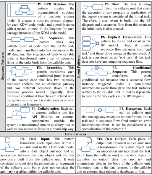
The L2-to-L3 transformation is based on ten business patterns, which identify specific structures of meta-classes in the KDM models and establishes other specific structures of business meta-classes in output models. The patterns are built taking into account business patterns that are usually used by business experts for modeling business processes [1, 25]. The patterns proposed in this paper specify additionally those structures of source code elements (defined through KDM elements) that originate the specific business structures in BPMN models.
Table 1 depicts the ten patterns grouped by category. There are three categories of patterns according to the type of elements managed by the pattern: (i) sequence patterns, (ii) event patterns, and (iii) data patterns.
Table 1. Business patterns implemented in the model transformation S e q u e n c e P a tt e r n s P1. BPD Skeleton. This
pattern creates the organizational structure of a business process model. It creates a business process diagram for each KDM code model and a pool instance with a nested process in the diagram for each package instance of the KDM code model.
E v e n t P a tt e r n s
P5. Start. The task building
from the callable unit that starts the execution of any program or application of the legacy system is considered the initial task. Therefore, a start event is built into the BP diagram and a sequence flow from this event to the initial task is also created.
P2. Sequence. This
pattern takes any callable piece of code from the KDM code model and maps them into task instances in the BP diagram. The sequence of calls to callable units is transformed into a set of sequence flows in the tasks built from the callable unit.
P6. Implicit Termination. This
pattern builds an end event in the BP model. Then, it creates sequence flow instances from ‘end task’ and those flows merge in the end event. A task is considered as an ‘end task’ if this task does not have any outgoing sequence flow.
P3. Branching. This
pattern transforms each conditional jump instance of the source code that has two mutually exclusive choices into an exclusive gateway and two different sequence flows in the business process model. Typically, those exclusive conditional branches are related with the if-then-else or switch statements in several programming languages.
P7. Conditional
Sequence. This pattern
transforms each conditional call instance into a sequence flow instance triggered under a conditional intermediate event through to the task instance related to the callable unit. It makes it possible to create arbitrary cycles in the BP diagram.
P4. Collaboration. Each call
to external callable unit (i.e. API libraries or external components outside the system) is transformed into an auxiliary task as well as two sequence flows in a round-trip way
P8. Exception. Each
call to callable unit that manage any exception is transformed into a task and a sequence flow fired under an error intermediate event. It can be considered as a specialization of the pattern P7.
Data Patterns
P9. Data Input. This pattern
transforms each input data within a callable unit in the KDM code model into a data object instance and an association between the data object and the task previously built from the callable unit. It only considers as input data the parameters or arguments of the callable unit, but it does not consider the auxiliary variables within the callable unit.
P10. Data Output. Each piece of
output data involved in a callable unit is transformed into a data object and an association instance from the task (built from the callable unit) to the data object. It excludes as output data the auxiliary and intermediate data in the body of the callable unit. The output data is the data returned by the callable unit or external data related to databases or files. 4.3 Implementation of the L2-to-L3 transformation
The model transformation is implemented by means of QVT-Relation. QVT-Relation is the selected language to implement the proposed patterns due to the fact that it is a declarative language, and therefore it facilitates the definition of declarative constraints that must be satisfied by the meta-class instances of the input and output models.
A model transformation defined through QVT-Relation language consists of a set of relations that specify two (or more) domains. A domain is a distinguished typed variable that can be matched in the type of a given model element. Input domains define a set of meta-classes of the input metamodel and a set of constraint bounded to
X
those meta-classes that must be satisfied. These domains are usually tagged with the
checkonly keyword. Moreover, outputs domains define a template of meta-classes and their properties that must be located, modified, or created in the output model to satisfy the relation. These domains are tagged with the enforce keyword.
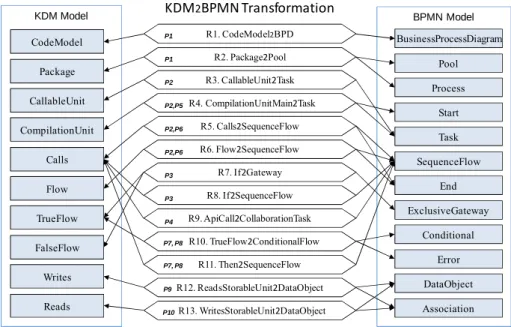
Fig. 6. Model transformation overview, relations and supported patterns.
The model transformation consists of thirteen relations. Fig. 6 shows an overview depicting: (i) each relation and its involved elements, as well as (ii) the patterns supported for each relation.
Due to the space limitation, this paper does not show all the relations, but the most significant ones in charge of model the sequence flows in the target business processes: relations R1, R2 and R4. Fig. 7 shows the relations R1 that implements the P1 pattern. R1 takes any instance of the CodeModel meta-class and generates a
BusinessProcessDiagram with the same name. In addition, it triggers the R2 relation in the where clause for each Package element belonging to the input domain.
top relation CodeModel2BPD { xName : String;
checkonly domain kdm cm : code::CodeModel { name = xName
};
enforce domain bpmn bpd : BusinessProcessDiagram { Name = xName
}; where {
cm.codeElement->forAll (pk:code::AbstractCodeElement | pk.oclIsKindOf(code::Package) implies Package2Pool(pk,bpd));
} }
Fig. 7. Relation R2.CodeModel2BPD to support partially the P1 pattern
R1. CodeModel2BPD R2. Package2Pool R3. CallableUnit2Task R4. CompilationUnitMain2Task R12. ReadsStorableUnit2DataObject R13. WritesStorableUnit2DataObject R5. Calls2SequenceFlow R6. Flow2SequenceFlow R7. If2Gateway R8. If2SequenceFlow R9. ApiCall2CollaborationTask R10. TrueFlow2ConditionalFlow R11. Then2SequenceFlow BPMN Model KDM Model CodeModel Package Flow CallableUnit CompilationUnit Writes Reads Calls Pool Association Process Start Task SequenceFlow DataObject End P1 KDM2BPMN Transformation TrueFlow FalseFlow Conditional Error BusinessProcessDiagram P1 P2 P2,P5 P2,P6 P2,P6 P3 P3 P4 P7, P8 P7, P8 P9 P10 ExclusiveGateway
relation Package2Pool { xName : String;
checkonly domain kdm pk : code::Package { name = xName
};
enforce domain bpmn bpd: BusinessProcessDiagram { Pools = p : Pool { name = xName, ProcessRef = pr : bpmn::Process { Name = xName } } }; where {
pk.codeElement->forAll (c:code::AbstractCodeElement | c.oclAsType(code::CompilationUnit) .codeElement>forAll(m:code::AbstractCodeElement |(m.oclIsKindOf(code::CallableUnit) and m.oclAsType (code::CallableUnit).name='main') implies CompilationUnitMain2Task(c,m, pr))); pk.codeElement->forAll (c:code::AbstractCodeElement | c.oclAsType(code::
CompilationUnit).codeElement->forAll(m:code::AbstractCodeElement|( m.oclIsKindOf (code::CallableUnit) and m.oclAsType (code::CallableUnit).name<>'main') implies CallableUnit2Task (m, pr)));
} }
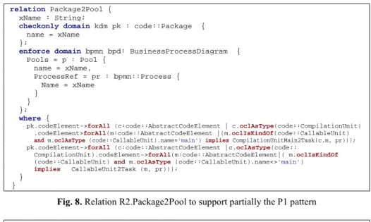
Fig. 8. Relation R2.Package2Pool to support partially the P1 pattern relation MethodUnit2Task {
xName : String;
checkonly domain kdm m : code::CallableUnit { name = xName
};
enforce domain bpmn pr : bpmn::Process { GraphicalElements = t : Task { Name = xName, Status = StatusType::Ready } }; where { ...
m.codeElement->forAll (a:code::AbstractCodeElement | a.oclIsKindOf(action:: ActionElement) and a.oclIsUndefined() implies ApiCall2CollaborationTask(a, t, pr));
...
m.codeElement->forAll (a:code::AbstractCodeElement | a.oclAsType(action:: ActionElement).actionRelation->forAll (w:action::AbstractActionRelationship | (w.oclIsKindOf(action::Writes)) and w.oclAsType(action::Writes).to.oclIsKindOf (code::StorableUnit) implies WritesStorableUnit2DataObject (w, t, pr))); ...
} }
Fig. 9. Relation R4.CallableUnit2Task to support partially the P2 pattern
The R2 relation defines the set of Package instances as input domain and instances of the BusinessProcessDiagram meta-class as output domain (see Fig. 8). R2 enforces the creation of a Pool and a nested Process instance, which will contain the remaining of business elements obtained through the proposed transformation. Also, R2 triggers the relations R3 and R4 that will define the Task instances of the business process.
Another important relation is R4.CallableUnit2Task (see Fig. 9). It defines the set of CallableUnit instances as input domain and enforces the creation of a Task instance in the process according to the argument in the call to this relation. In addition, the
where clause (that can be understood as post-conditions of the relation) triggers the remaining of relations in order to fill the business process with elements obtained from another elements within callable units. Moreover, the R4 relation shows the calls to relations R9.ApiCall2CollaborationTask and R13.WritesStorableUnit2DataObject.
5 Case Study
The presented case study applies the KDM2BPMN transformation to a legacy system, which is based on the case study protocol of Brereton et al. [2]. Next subsections show the case study details according to the protocol: design, case selection, case study procedure, data collection and analysis.
Design
This case study applies the proposed model transformation to a legacy system. Data related to transformation is registered and then analyzed. The unit of analysis of the study is the code packages of legacy system, thus it considers multiple units of analysis. In addition, the case study establishes the following research questions to analyze the obtained results:
Q1. Are the obtained business process models cohesive?
Q2. What is the degree of coupling of the business process models? Q3. Is the execution of the transformation efficient?
Questions Q1 and Q2 are related to the quality of the obtained business process diagram, which is measured by means of cohesion (1) and coupling (2) metrics proposed by Rolón et al. [20]. Moreover, question Q3 is related to the time spent on executing the transformation that is analyzed with respect to the total number of elements built into the business process model.
ܥܱܪܧܵܫܱܰ = ܰݑܾ݉݁ݎ ݂ ݐܽݏ݇ݏ
ܰݑܾ݉݁ݎ ݂ ݏ݁ݍݑ݁݊ܿ݁ ݂݈ݓݏ ܾ݁ݐݓ݁݁݊ ݐܽݏ݇ݏ (1) ܥܱܷܲܮܫܰܩ =ܰݑܾ݉݁ݎ ݂ ݑݐݑݐ ݀ܽݐܽ ܾ݆݁ܿݐݏ
ܰݑܾ݉݁ݎ ݂ ݐܽݏ݇ݏ (2)
Case selection
In order to select an appropriate case under study, the most suitable legacy system, the following criteria are defined: (i) the system should be a real-life system; and (ii) it should be an enterprise system.
After the application of those criteria, the selected case was an open source CRM system: Source Tap CRM [22]. It provides a powerful sales management system to improve a sales organization's productivity, allowing management to plan ahead of economic changes in order to effectively manage any market condition. This system, written in Java, consists of 170 source code files divided into 27 packages, and the size of the system is 49.6 KLOC.
Case study procedure
The execution procedure of the case study consists of four stages: firstly, (i) the source code is analyzed and the KDM code models are generated (the first and second MARBLE transformation); secondly (ii) the KDM code models are transformed into BPMN models by the proposed transformation that is executed through MediniQVT, a model transformation engine for QVT Relation; thirdly, (iii) the BPMN models are inspected and several measures are taken; and finally, (iv) the conclusions of the case study are obtained by means of the analysis of the measured values.
Data Collection
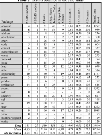
Table 2 summarizes the data collected after the execution of the transformation: the
package column represents the source code package which is transformed into a business process model; #KDM models and #BPM: models represent the number of
those models obtained; #Tasks, #Seq. Flows between Tasks and #Output Data Objects
are the three base metrics to calculate COHESIO: (1) and COUPLI:G (2) metrics;
#Elements represents the total number of elements; and finally Transf. time (ms)
represents the milliseconds spent to obtain each BPMN model. Table 2. Results obtained in the case study
Package # K D M m o d el s # B P M N m o d el s # T as k s # S eq . F lo w s b et w ee n T as k s # O u tp u t D at a O b je ct s C O H E S IO N C O U P L IN G # E le m en ts T ra n sf . ti m e (m s) account 4 1 31 48 7 0,65 0,23 163 1292 activity 6 1 34 56 9 0,61 0,26 210 959 address 2 1 8 12 4 0,67 0,50 59 276 attachment 3 1 13 18 2 0,72 0,15 76 300 chart 1 1 26 48 9 0,54 0,35 164 2899 code 5 1 13 18 1 0,72 0,08 66 604 contact 6 1 20 26 1 0,77 0,05 109 337 customization 14 1 18 44 7 0,41 0,39 237 1948 event 1 1 13 6 1 2,17 0,08 50 293 forecast 2 1 7 8 3 0,88 0,43 33 194 issue 4 1 15 26 1 0,58 0,07 95 450 lead 11 1 32 54 12 0,59 0,38 195 679 note 2 1 9 14 1 0,64 0,11 50 314 opportunity 10 1 40 76 19 0,53 0,48 289 1167 party 3 1 15 18 2 0,83 0,13 65 252 product 1 1 6 16 0 0,38 0,00 41 172 replication 14 1 17 28 1 0,61 0,06 105 545 report 1 1 7 12 9 0,58 1,29 111 4572 role 0 1 - - - - - 0 98 security 6 1 18 20 11 0,90 0,61 126 627 sql 1 1 5 6 3 0,83 0,60 30 168 ui 19 1 100 210 41 0,48 0,41 667 5841 user 3 1 20 42 1 0,48 0,05 115 1222 util 9 1 66 48 17 1,38 0,26 261 1088 view 0 1 - - - - - 0 95 multipartrequest 2 1 2 0 0 0 0,00 8 129 entity 1 1 5 0 0 0 0,00 10 129 Total 131 27 540 854 162 16,92 6,95 3335 26650 Mean 4,85 1,0 21,60 34,16 6,48 0,74 0,28 123,5 987,04 Std Deviation 4,94 0,0 21,54 41,71 8,98 0,38 0,29 135,4 1385,9 Analysis
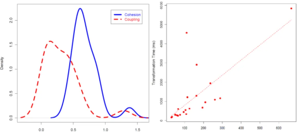
A set of 27 BPMN models was obtained after the execution. Then, the collected data is analyzed in order to draw conclusions. In order to respond to questions Q1 and
Q2, Fig. 10 (left side) shows the density charts of the Coupling and Cohesion. Both density functions follow a normal distribution, approximately. Cohesion has a mean of 0.74 that is more close to 1.0. Coupling has a mean of 0.28 that is close to zero. Thus, the transformation can obtain cohesive and loosely coupled BPMN models.
Additionally, the transformation time is analyzed in order to answer question Q3. The 27 BPMN models were obtained with an average size of 21.6 tasks per diagram and an average time of 0.99 seconds. In addition, the feasibility of the time values for systems that are larger than Source Tap CRM must be evaluated. Fig. 10 (right side) shows the scatter chart of size/time which reports a linear relationship between the size and time spent on the execution. Due to the fact that the size/time relationship is not exponential, the time increase for large systems will be predictable.
Fig. 10. Density chart cohesion/coupling (left side) and the scatter chart size/time (right side)
6 Related Work
There are a lot of works in literature related to the recovery of business knowledge from legacy information systems. Cai et al. [3] propose an hybrid approach that combines the requirement reacquisition with dynamic and static analysis technique in order to extract complex business processes that are triggered by external actors. Firstly, a set of use cases are recovered by means of interviewing the users of the legacy system. Secondly, according to those use cases, the system is dynamically traced. Finally, the traces are statically analyzed to recover business processes.
Zou et al [26] developed a framework based on the MDA approach that uses the static analysis of source code as technique for extracting business processes by means of a set of heuristic rules to transform code entities into business entities. Moreover, the legacy source code is not the only artefact analyzed to obtain business processes.
Di Francescomarino et al consider user interfaces [4]; this work proposes a technique for recovering Business Processes by means of a dynamic analysis of the GUI-forms of the Web applications that are exercised throughout the user navigation. The database is another artefact used to recover business knowledge. Paradauskas et al.
[15] present a framework to recover business logic through the analysis of the data stored in databases. Also, Perez-Castillo et al. [18] propose a reengineering framework to extract business logic from relational database schemas. In other cases, documentation is also used to recover process. Ghoseet al [5] propose a set of text-based queries in source code and documentation for extracting business knowledge from systems.
Despite the fact that business process recovery or business knowledge has been widely studied for many years, the proposals lack of the model-based formalization, standardization and interchange common format that provide ADM and KDM.
Izquierdo, J. L. C. and J. G. Molina [7] propose a domain specific language for extracting models in ADM-based processes using Gra2MoL. In addition, Perez-Castillo et al. propose MARBLE [16], the ADM-based framework using KDM presented in this paper.
7 Conclusion
This paper proposes the KDM2BPMN model transformation within MARBLE, an ADM-based framework to rebuilt business processes embedded in legacy systems in order to facilitate and improve the evolutionary maintenance. For instance, when a new modification is requested, MARBLE facilitates the source code location of those business process concepts related to the required modification.
The KDM2BPMN transformation focuses on transform KDM code model into BPMN models that represents the business processes. The transformation is implemented by means of QVT-Relation, since it facilitates the implementation of the set of business patterns. The patterns define what parts of legacy code are transformed into specific business elements. The obtained business processes are undoubtedly preliminary, since there is a lot of business knowledge that is not embedded in source code. In a desirable scenario, the obtained business processes should be refined by the business experts as proposed in MARBLE. Despite this fact, the business processes obtained through the transformation help maintainers and business experts to comprehend the system in the business environment.
In addition, the case study reported that the proposed transformation can obtain BPMN models in a cohesive and non-coupling manner. Also, it reports that the transformation can be scalable to large legacy systems, since the business process models were obtained in linear time with respect to the size of the models.
The future extensions of this work will focus on addressing case studies with enterprise legacy systems, where system and business experts will assess the extent to which business processes represent faithfully the company’s operation. Moreover, these case studies may also help to detect new business structure needs that will provide the definition of more refined patterns.
Acknowledgement
This work was supported by the FPU Spanish Program; by the R&D projects funded by JCCM: ALTAMIRA (PII2I09-0106-2463), INGENIO (PAC08-0154-9262) and PRALIN (PAC08-0121-1374); and the PEGASO/MAGO project (TIN2009-13718-C02-01) funded by MICINN and FEDER.
References
[1] Aalst, W.M.P.v.d., A.H.M.t. Hofstede, B. Kiepuszewski, and A.P. Barros., "Workflow Patterns".Distributed and Parallel Databases, 2003. 14(3): p. 5-51.
[2] Brereton, P., B. Kitchenham, D. Budgen, and Z. Li. "Using a protocol template for case study planning". in Evaluation and Assessment in Software Engineering (EASE'08). 2008. Bari, Italia p. 1-8.
[3] Cai, Z., X. Yang, and W. Wang. "Business Process Recovery for System Maintenance - An Empirical Approach". in 25 th International Conference on Software Maintenance
(ICSM'09). 2009. Edmonton, Canada: IEEE CS p. 399-402.
[4] Di Francescomarino, C., A. Marchetto, and P. Tonella. "Reverse Engineering of Business Processes exposed as Web Applications". in 13th European Conference on Software
Maintenance and Reengineering (CSMR'09). 2009. Fraunhofer IESE, Kaiserslautern,
[5] Ghose, A., G. Koliadis, and A. Chueng. "Process Discovery from Model and Text Artefacts". in IEEE Congress on Services (Services'07). 2007 p. 167-174.
[6] ISO/IEC, ISO/IEC DIS 19506. Knowledge Discovery Meta-model (KDM), v1.1
(Architecture-Driven Modernization). http://www.iso.org/iso/catalogue_detail.htm?
csnumber=32625. 2009, ISO/IEC. p. 302.
[7] Izquierdo, J.L.C. and J.G. Molina. "A Domain Specific Language for Extracting Models in Software Modernization". in Proceedings of the 5th European Conference on Model
Driven Architecture - Foundations and Applications. 2009. Enschede, The Netherlands:
Springer-Verlag p. 82-97.
[8] Jeston, J., J. Nelis, and T. Davenport, Business Process Management: Practical Guidelines
to Successful Implementations. 2008, NV, USA: Butterworth-Heinemann (Elsevier Ltd.).
[9] Khusidman, V. and W. Ulrich, Architecture-Driven Modernization: Transforming the
Enterprise. DRAFT V.5. http://www.omg.org/docs/admtf/07-12-01.pdf. 2007, OMG.
[10] Moyer, B. (2009) Software Archeology. Modernizing Old Systems. Embedded Technology Journal, http://adm.omg.org/docs/Software_Archeology_4-Mar-2009.pdf
[11] OMG. ADM Task Force by OMG. 2007 9/06/2009 [cited 2008 15/06/2009]; Available from: http://www.omg.org/.
[12] OMG, Business Process Model and :otation (BPM:) 2.0. 2008, Object Management Group: Needham, MA 02494 USA. p. 34.
[13] OMG, QVT. Meta Object Facility (MOF) 2.0 Query/View/Transformation Specification.
http://www.omg.org/spec/QVT/1.0/PDF. 2008, OMG.
[14] OMG, Architecture-Driven Modernization (ADM): Knowledge Discovery Meta-Model
(KDM), v1.1. http://www.omg.org/spec/KDM/1.1/PDF/. 2009, OMG. p. 308.
[15] Paradauskas, B. and A. Laurikaitis, "Business Knowledge Extraction from Legacy Information Systems".Journal of Inf. Tech. and Control, 2006. 35(3): p. 214-221. [16] Pérez-Castillo, R., I. García-Rodríguez de Guzmán, O. Ávila-García, and M. Piattini.
"MARBLE: A Modernization Approach for Recovering Business Processes from Legacy Systems". in International Workshop on Reverse Engineering Models from Software
Artifacts (REM'09). 2009. Lille, France: Simula Research Laboratory Reports p. 17-20.
[17] Pérez-Castillo, R., I. García-Rodríguez de Guzmán, O. Ávila-García, and M. Piattini. "Business Process Patterns for Software Archeology". in 25th Annual ACM Symposium on
Applied Computing (SAC'10). 2010. Sierre, Switzerland: ACM p. 165-166.
[18] Pérez-Castillo, R., I. García-Rodríguez de Guzmán, I. Caballero, M. Polo, and M. Piattini. "PRECISO: A Reengineering Process and a Tool for Database Modernisation through Web Services ". in 24th ACM Symposium on Applied Computing. 2009. p. 2126-2133. [19] Polo, M., M. Piattini, and F. Ruiz, Advances in software maintenance management:
technologies and solutions. 2003: Idea Group Publishing.
[20] Rolón, E., F. Ruiz, F. García, and M. Piattini. "Evaluation measures for business process models". in 21th ACM Symposium on Applied Computing. 2006. p. 1567-1568.
[21] Sneed, H.M., Estimating the Costs of a Reengineering Project. Proceedings of the 12th Working Conference on Reverse Engineering. 2005: IEEE Computer Society.
[22] Source Tap, Source Tap CRM. http://sourcetapcrm.sourceforge.net/. 2009.
[23] Visaggio, G., "Ageing of a data-intensive legacy system: symptoms and remedies".
Journal of Software Maintenance, 2001. 13(5): p. 281-308.
[24] Weske, M., Business Process Management: Concepts, Languages, Architectures. 2007, Leipzig, Alemania: Springer-Verlag Berlin Heidelberg.
[25] Zdun, U., C. Hentrich, and S. Dustdar, "Modeling process-driven and service-oriented architectures using patterns and pattern primitives".ACM Trans. Web, 2007. 1(3): p. 14. [26] Zou, Y., T.C. Lau, K. Kontogiannis, T. Tong, and R. McKegney. "Model-Driven Business
Process Recovery". in Proceedings of the 11th Working Conference on Reverse