DBM series
DBM 2030/2040
DBM 2540/2550
DBM 3050/3060/3080
DBM
series
Multi-purpose Double Column
Machining Center
Product Preview Basic information Broad Range of Machining Capabilities High-Precision, High-Speed Mold Machining Performance Convenient Machining Functions Machine Information Standard/Optional Specifications Machine Specifications Customer Support
DBM
series
The DBM series is a multi-purpose double column machining center without W-axis for applications such
as heavy duty machining of large parts and high precision dies and molds. Designed with the highest
specifications in its class, the DBM series provides a broad range of machining capabilities and optional
equipment, together with many convenient functions for the operator.
Contents
02
Product Preview
Basic information
04
Broad Range of Machining
Capabilities
12
High-Precision, High-Speed Mold
Machining Performance
14
Convenient Machining Functions
Machine Information
16
Standard/Optional Specifications
24
Machine Specifications
26
Customer Support
Broad Range of Machining Capabilities
A variety of different ram spindle specifications
and a wide range of auto-change attachments
support many types of machining applications
such as dies/molds to heavy duty cutting.
High-Precision, High-speed Mold
Machining Performanc
e
Adoption of the DSQ I/II/III functions,
speed rapid traverse and cutting feedrate,
high-load table capacity, high-precision/highspeed
head attachments, X/Y/Z axes linear scale, or
X/Y/Z axes ball screw shaft cooling as options
enables the machining of high-accuracy and
high-speed molds and general parts.
Convenient Machining Functions
The DBM series provides a support system for
5 face machining of large and heavy
workpieces, easy pattern cycles, work load
counter control, automatic feed control, and
process monitoring function.
Structure temperature sensors Spindle temperature sensor
Designed for large work
pieces, the machine
enables long-term,
heavy-duty cutting
with stable machining
accuracy.
rigidity,
High-precision Structure
Equipped with roller
LM Guideways for
increased rigidity and
a cooling system as
a standard feature
to minimize thermal
displacement at X/Y axis
Feed Axis
Bed and Column Structure
• The structure of the DCM series
minimizes the effects of vibration on
workpieces under loads produced by
both vertical and horizontal cutting
during machining of 5 faces. Symmetrical
structure design and the application of
effective compensation reduces thermal
displacement during machining.
• The bed is made of an M-type cast
structure excellent for vibration
absorption to ensure a high level of
machining accuracy.
• The cross beam has a guideway
structure of the I-shaped to have high
accuracy and rigidity.
• Thermal compensation
Z-axis nut-housing cooling as Standard
Minimized thermal impact to the ram
spindle.
High rigidity / Accuracy
Stable and Fast Feed Shaft Structure
Thermal compensation as standard
• Structure thermal compensation
Multiple thermal sensors are attached
to minimize and compensate thermal
displacement of the spindle and the
structure.
Ball screw bearing housing cooling and
Z-axis dual ball screw
• Minimized axes displacement to apply
ball screw bearing housing cooling
• High speed,
high accuracy control
with Z-axis dual ball screw
Cross-beam Structure
Product Preview Basic information Broad Range of Machining Capabilities High-Precision, High-Speed Mold Machining Performance Convenient Machining Functions Machine Information Standard/Optional Specifications Machine Specifications Customer SupportCross-beam Structure
Wide Machining
Specifications
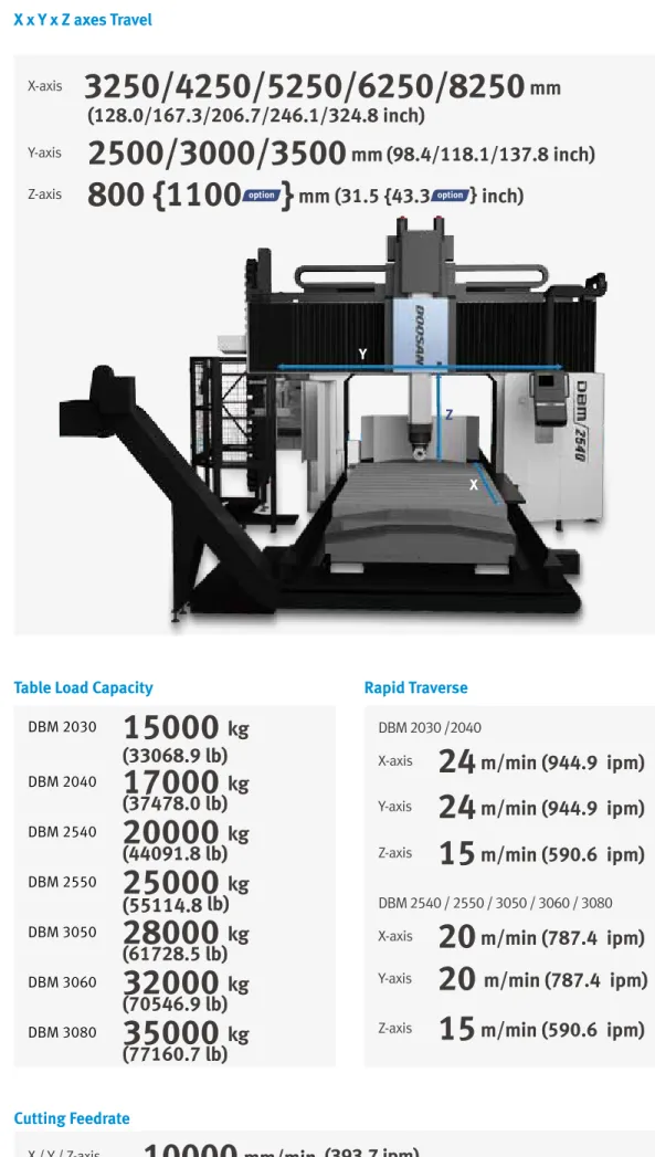
X x Y x Z axes Travel
※ Specifications and delivery of DBM 2540/2550should be reviewed in detail before contract.
Cutting Feedrate
Y
X
Z
X-axis
3250/4250/5250/6250/8250
mm
(128.0/167.3/206.7/246.1/324.8 inch)
Y-axis
2500/3000/3500
mm
(98.4/118.1/137.8 inch)
Z-axis
800 {1100 }
mm (31.5 {43.3
} inch)
X / Y / Z-axis
10000
mm/min (393.7 ipm)
Table Load Capacity
Rapid Traverse
DBM 2030
15000
kg
(33068.9 lb)
DBM 2040
17000
kg
(37478.0 lb)
DBM 2540
20000
kg
(44091.8 lb)
DBM 2550
25000
kg
(55114.8 lb)
DBM 3050
28000
kg
(61728.5 lb)
DBM 3060
32000
kg
(70546.9 lb)
DBM 3080
35000
kg
(77160.7 lb)
DBM 2030 /2040
X-axis
24
m/min (944.9 ipm)
Y-axis
24
m/min (944.9 ipm)
Z-axis
15
m/min (590.6 ipm)
DBM 2540 / 2550 / 3050 / 3060 / 3080
X-axis
20
m/min (787.4 ipm)
Y-axis
20
m/min (787.4 ipm)
Product Preview Basic information Broad Range of Machining Capabilities High-Precision, High-Speed Mold Machining Performance Convenient Machining Functions Machine Information Standard/Optional Specifications Machine Specifications Customer Support
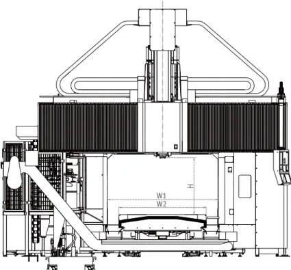
Effective width between columns W1
Workpiece height H
Table size in Y and X axis W2 x L
W1 H W2 W1 H W2
Wide Machining
Specifications
L2000/2500/3000
mm
(78.7/98.4/118.1 inch)
W2
1500/2000/2500
mm
(59.1/78.7/98.4 inch)
L
3000/4000/5000
mm
(118.1/157.5/196.9 inch)
6000/8000
mm
(236.2/315.0 inch)
1000
{1300 }
mm
(39.4{51.2
}inch)
Adoption of ram spindle and saddle structure to support heavy-duty cutting
The highly rigid, square type box guideway ram has a cross section of 380 x 380mm(14.96 x 14.96 inch),
which is the biggest in its class. This ensures optimum heavy duty machining capability in both vertical and
horizontal applications.
X + direction X + direction Y + direction Y + direction
Stress analysis of ram spindle unit
The ram spindle unit is designed to maintain ideal conditions under any load through stress analysis.
Ram
spindle
Saddle
High rigidity & speed
machining with high
power ram spindle.
High Power Ram Spindle
6000 r/min
8000 r/min
Spindle Power – Torque Diagram
Product Preview Basic information Broad Range of Machining Capabilities High-Precision, High-Speed Mold Machining Performance Convenient Machining Functions Machine Information Standard/Optional Specifications Machine Specifications Customer SupportSpindle speed : r/min
0 350 380 900 1,030 1,900 3,000 6,000 553 (408.1) 1009 (744.6) 653 (481.9) 37 (49.6) 55 (73.8) 45 (60.3) S3 25% S2 30% Continuous 500 LOW HIGH 26 (34.9) 37 (49.6) 186 (137.3) 22 (29.5) 226 (166.8) 276 (203.7) Po w er : kW (H p) To rq ue : N ·m (f t-lb s)
Spindle speed : r/min
0 350 380 900 1,030 1,900 3,000 8,000 553 (408.1) 1009 (744.6) 653 (481.9) 37 (49.6) 55 (73.8) 45 (60.3) S3 25% S2 30% Continuous 500 LOW HIGH 22 (29.5) 26 (34.9) 37 (49.6) 186 (137.3) 226 (166.8) 276 (203.7) Po w er : kW (H p) To rq ue : N ·m (f t-lb s)
6000
r/min
Spindle speed
Spindle power
55/37
kW
(73.8 / 49.6 Hp)
1009
N.m
Spindle torque
(744.6 ft-lbs)
8000
r/min
Spindle speed
Spindle power
55/37
kW
(73.8 / 49.6 Hp)
1009
N.m
Spindle torque
Diverse head attachments for a wider range of machining applications
Features Standard Dummy Cover Extension 90° Angle
Spindle Air Curtain Standard Standard
-Flood Coolant / Air Blow Standard Standard Standard
Head Attachment Tool Unclamp Standard Standard Standard
Head Attachment Spindle Air Purge Standard Standard Standard
TSC (Through Spindle Coolant)
※ The provided utility line could be different as choosing the head attachment.
※ When 10/15/30/45 degree angle attachment, or U-frame universal head is considered for purchase, please contact Doosan for detailed specifications.
A diverse range of auto-change head attachments enables the machining of a variety of complex shapes, from 5 axis
simultaneous processing of Molds to angled faces using 1 degree indexing, as well as 5 face machining. Head indexing
is achieved by C axis control through the ram
Various Auto-Change
Head Attachments
Various utilities are available to keep the same level of performance even when the head attachment is changed.
Provides numerous utilities to ensure the same performance provided by the original ram spindle even after
changing a Head Attachment
U frame simultaneous 5-axis universal head Head attachment
General parts machining Mold, complex shape machining Universal head 90° Angle
Standard Dummy Cover
Extension
10°/15°/ 30°/45° Angle
290 250 106 350 456 Ø220 400/600 Ø210 600
F Frame Head Attachment
U Frame Simultaneous 5-Axis Universal Head
High speed 90° angle
• 6000 r/min, 15 kW (20.1 Hp), min. 5/1° indexingExtension
• 6000 r/min, 22 kW (29.5 Hp)90° angle
• 4000 r/min, 22 kW (29.5 Hp), min. 5/1° indexing
High-speed extension
• 6000~12000 r/min, 15/11 kW (20.1/14.8 Hp)10° / 15° / 40° Angle
Standard Dummy Cover
Unit: mm (inch)
High-speed, high-precision built-in driven universal
head 15000 r/min
• B axis 0.001° Continuous • C axis 0.001° Continuous Product Preview Basic information Broad Range of Machining Capabilities High-Precision, High-Speed Mold Machining Performance Convenient Machining Functions Machine Information Standard/Optional Specifications Machine Specifications Customer SupportAutomatic Head
Attachment Changer
(AAC)
Swing AAC-2 Stations
Two types of head attachment including dummy cover and 90° angle are equipped as a standard feature to
minimize the time required to change a head attachment.
Up-Down AAC-1 Stations
High-speed, High-precision Contouring Control
The linear scale feedback system provides
high positioning accuracy in the X, Y, Z,
and W axes.
The heat generated in the ball screw is
removed by a high-efficiency cooler to
minimize thermal deformation of the ball
screw.
For faster removal of frictional heat, a
hollow ball screw shaft through which the
coolant oil flows is equipped.
X/Y/Z-axis Linear Scale Feedback System
X/Y/Z-axis Ball Screw Shaft Cooling
High-Precision Mold
Machining
*
DSQ : Doosan Super QualityCutting condition R1 R2 R3 R4 R5 R6 R7 R8 R9 R10
Quality Normal Excellent
Tool life Long Normal
Application High-speed roughing High-precision finishing
• Use the R code in the program to change the cutting condition by up to 10 steps. - Improved productivity (high-speed roughing, high-precision finishing)
• Various servo-related NC parameters such as acceleration and deceleration time constants and maximum cutting feed can be set automatically.
Cutting condition selection function
• DSQ
I
(AICC
II
_ 200 Block + Machining condition selection function)
• DSQ
II
(DSQ
I
+ Data server [1GB])
• DSQ
III
(DSQ
II
+ High speed processing _ 600 Block)
High-precision, High-speed Head Attachments and Universal Head Specialized for
Mold Machining
Optimized mold machining can be achieved by selecting various head attachments and ram
spindles specialized for diverse mold shapes and high-speed mold machining.
High-speed 90° angle 6000 r/min, 15 kW (20.1Hp), min 5/1° indexing 290 250 106 350 456 Ø220 400/600 Ø210 600 297 247 200 250 585 835 300 246 220 290 800 1090 408 358 408 395 523 918
High-speed, high-precision built-in driven 5-axis
simultaneous universal head 15000r/min B axis 0.001° Continuous C axis 0.001° Continuous 290 250 106 350 456 Ø220 400/600 Ø210 600 297 247 200 250 585 835 300 246 220 290 800 1090 408 358 408 395 523 918 High-speed extension 6000~12000 r/min, 15/11 kW (20.1/14.8 Hp) 290 250 106 350 456 Ø220 400/600 Ø210 600 297 247 200 250 585 835 800 1090 395 523 918
Verification sample VASE
DSQ applied DSQ not applied
Product Preview Basic information Broad Range of Machining Capabilities High-Precision, High-Speed Mold Machining Performance Convenient Machining Functions Machine Information Standard/Optional Specifications Machine Specifications Customer Support
5-face machining support system
Convenient Machining
Supporting functions for 5-face machining
• 3-dimentional-work coordinates
conversion system
• Tool end point shift within work
coordinate system
• AAC control and head attachment
position control by M-Code
• ATC is applicable for various head
attachments.
※ These functions are provided as a standard package when the 5 face machining head attachment is supplied.
Programming time can be dramatically reduced by
creating cutting programs and inputting the major
parameters of the cutting pattern cycle required for
parts cutting. The function is embedded in the CNC for
convenient use in the field. Up to 22 complex pattern
cycles including basic 5 patterns are available.
Easy Pattern Cycle
DOOSAN CONVERSATION MACHINING
Example) Milling pattern
Example) Hole pattern
• Automatic head attachment offset measurement(G120)
Y Y Y Z Z Z X X X X X Y Y Z Z Extension head attachment
(G100 X Y Z … )
90° angle head attachment 270° indexing (G100 C270 X Y Z … )
90° angle head attachment 180° indexing (G100 C180 X Y Z … )
90° angle head attachment 90° indexing (G100 C90 X Y Z … ) 90° angle head attachment
0° indexing (G100 C0 X Y Z … )
If customer selects proper M-Code according to weight of the work piece, the machine can decide
itself the best movin g pattern of the table. And machining can progress by this decision.
M-Code Weight of work piece DBM2540 DBM2550
M380 5 tons(11023.0 lb) or less • •
M381 10 tons(22045.9 lb) or less • •
M382 15 tons(33068.9 lb) or less • •
M383 20 tons(44091.8 lb) or less • •
Work load counter control
Adaptive Feedrate Control(AFC)
with M-CODE Feedrate Time without M-CODE Product Preview Basic information Broad Range of Machining Capabilities High-Precision, High-Speed Mold Machining Performance Convenient Machining Functions Machine Information Standard/Optional Specifications Machine Specifications Customer Support
If tool overload is detected during operation, the feed rate is controlled to prevent the tool from
being damaged.
without AFC with AFC
In-process monitoring minimizes the risk of damage to the workpiece during cutting
Process monitoring function and manual operation screen
Tool load monitoring
During cutting operation, abnormal load caused by wear and tear of the tool is detected and an alarm is triggered to prevent further damage.
ATC manual
operation
screen
Tool management
This function controls information on the tools in the tool magazine pots.
Convenient Machining
Left-right-up-down pull type pendant arm operation panel.
Enhanced operator’s convenience
• In order to increase the brightness around the ram spindle to improve the workability, 2 to 3 work lights at the
bottom of the cross rail and 2 work lights at the bottom of the ram saddle are provided as standard according
to the model. (
▒
mark)
• The pulse handle, manual handle (portable MPG) or others enabling easy setup of work pieces for the
operator's convenience are provided as a standard feature or option.
Manual handle
Portable MPG handle Manual Portable 3 MPG
Manual handle
MPG with LCD display
Manual operation panel HMOP(Handy Machine
Operator’s Panel)
▒
▒
NO Division Description DBM series
1 Electric cabinet light
2 Electric cabinet air conditioner
3
High-quality machining (DOOSAN SUPER QUALITY)
DSQ I : AICCII+MACHINING CONDITION SELECTION
4 DSQ II : DSQ I+DATA SERVER (1GB)
5 DSQ III : DSQ II+HIGH SPEED PROCESSING_600 Block)
6 Tool management
7 Tool shank BT50
8 CAT50
9 DIN50
10 Tool magazine 40 tools
11 60 tools
12 90 tools
13 120 tools
14 Work load counter control
15 Electric leakage breaker
16 Electric line filter
17
Ram spindle
6000 r/min (Built-in) 55/37 kW (FANUC)
18 8000 r/min (Built-in) 55/37 kW (FANUC)
19 Spindle Cooling device
20 Bearing Housing Cooling
21 Spindle thermal compensation
22 Linear scale feedback system X / Y / Z-axis
23
Lift-up chip conveyor
HINGED PLATE
24 MAGNETIC SCRAPER
25 Components for installation eveling blocks and anchoring bolts
26 Hydraulic power unit
27 Bellows cover for axis Y-axis
28 Sliding covers for axes X-axis
29 Easy pattern cycle
30
Automatic tool length measurement TS27R_RENISHAW
31 NC4_RENISHAW
32 Automatic workpiece measurement OMP60_RENISHAW
33 RMP60_RENISHAW
34 Master tool for automatic tool length measurement CALIBRATION BLOCK
35 Automatic attachment changer (AAC) LINEAR TYPE (2-ST)
Swing AAC-2 Stations
Up-Down AAC-1 Stations
36 Auto power on
Various Optional Equipment
Various options to
satisfy the customers’
requirements can be
selected and applied.
Product Preview Basic information Broad Range of Machining Capabilities High-Precision, High-Speed Mold Machining Performance Convenient Machining Functions Machine Information Standard/Optional Specifications Machine Specifications Customer Support Standard Optional X Not applicable
NO Division Description DBM
series
38 Work light LED lamps : 4EA
39 Operator call lamp
(Red/Yellow/Green)
40 Tool load monitoring
41
Coolant tank
500L (118.9 galon)
42 1000L (264.2 galon)
43 Periodical checking function
44 Main operation panel(pendent type) POLE TYPE
45 Max. tool weight 30KG(66.1 lb)
46 Max. tool length 400mm(15.7 inch)
47
Chip & coolant protective cover CHIP COVER
48 SEMI GUARD
49 Coolant FLOOD (1.8kw)
50 Coolant gun
51 Coolant level switch : Sensing level - Low
52 Test bar BT50
53 Table T-slot 24H8
54 28H8
55 Chip bucketRotary type (380L) (100.4 galon)
56 Lift type (380L) (100.4 galon)
57 High column +300mm (11.8 inch)
58 AIR AIR BLOWER
59 AIR PURGE
60 AIR CURTAIN
61 AIR GUN
62 AIR DRYER
63 CS control BZ sensor
64 Display unit 10.4" COLOR LCD
65 15" COLOR LCD
66 Head attachment DUMMY HEAD
67 EXTENSION HEAD (L400/6K R/MIN)
69 EXTENSION HEAD (L600/6K R/MIN)
70 EXTENSION HEAD (L600/12K R/MIN)
71 90D ANGLE HEAD (L350/4K R/MIN)
73 90D ANGLE HEAD (L350/6K R/MIN)
75 90° head attachment indexing angle 5˚
76 1˚
NO Division Description DBM series 77 MPG PORTABLE TYPE 1-MPG
78 MPG WITH LCD DISPLAY
79 PORTABLE TYPE 3-MPG
80 HMOP(Handy Machine Operator's Panel)
81
NC Controller
FANUC 31i
82 HEIDENHAIN TNC640
83 SIEMENS 840D
84 Oil skimmer BELT TYPE
85 Pull stud MAS 403 P50T-1 (45˚)
86 MAS 403 P50T-2 (60˚)
87 TSC NONE
88 1.5 kW_2.0 MPa
89 TSA(Through Spindle Air) 0.5 Mpa
90 U frame universal head UNIVERSAL CONTOURING HEAD (15K R/MIN)
91
2-side chip conveyor (in machine to tank)
HINGED PLATE
92 MAGNETIC SCRAPER
93 5-face machining support system
94 Rotary TablePACKAGE #1 : ONLY WIRING
95 PACKAGE #2 : HYD. & CONTROL READY
96 PACKAGE #3 : FULL OPT.
97
Installation Type
UNDER GROUND FL-960 INSTALL (TABLE TOP_FL0)
98 GROUND FL0 INSTALL
(TABLE TOP_FL-960)
Automatic Tool Changer (ATC)
One arm performs the changes for both the horizontal and vertical spindle. The next tool to be used, regardless of the spindle location,
is brought to the standby position during cutting. The most reliable ATC and magazine with its servo motor & Hyd minimize downtime.
Horizontal ATC
operation with a
90° head attach
mounted.
Max. No. of tools 40 [ 60, 90] EA
Max. tool diameter 130 [near pot empty: 250] mm (5.1 [near pot empty: 9.8] inch)
Max. tool length 400mm (15.7 inch)
Max. tool weight 30 kg (66.1 lb)
Tool selection type Fixed address
Tool changing time (T-T) 5.5 s
※ Picture-Vertical ATC in operation
Horizontal type
Vertical type
Automatic Tool measurement
NC4
TS27R
Tool length can be measured in the vertical and horizontal
directions. The length of tool set up on the spindle is measured
automatically, and the tool offset data of the tool number are
entered automatically.
Product Preview Basic information Broad Range of Machining Capabilities High-Precision, High-Speed Mold Machining Performance Convenient Machining Functions Machine Information Standard/Optional Specifications Machine Specifications Customer SupportOptional chip conveyors are available to discharge chips and improved
to prevent chips and coolant from falling on the floor.
Forklift type
The bottom of the chip bucket has a space into which forks can be inserted to allowtransportation by a forklift .
Rotation type
The chip bucket is fitted with a rotating joint for tilting and emptying the bucket.
Chip Bucket
Forklift type
Lift-up chip conveyor
Chip Conveyor
Semi-guard
The semi-guard covers the entire cutting area to prevent chips and coolant from
flying off during cutting operation.
Rear cover to prevent chips and coolant from flying off
Chip protective door for the operator
Door opens when the ATC and AAC operate
Front cover to prevent chips and coolant from flying off
※ The hinged-plate chip conveyor and the magnetic scraper chip conveyor are optional features.
※ The discharge direction can be selected forward or backward. However, DBM 2030 can only be selected from the front.
Top View
Front View
External Dimensions
C D E A F H(TABLE to SPD.) W(BETWEEN COLUMNS) FL.O Product Preview Basic information Broad Range of Machining Capabilities High-Precision, High-Speed Mold Machining Performance Convenient Machining Functions Machine Information Standard/Optional Specifications Machine Specifications Customer Support LIFT UP CHIP CONVEYOR COOLANT TANK ATC DOOR ATC & MAGAZINEHYD.UNIT OIL COOLER
CONTROL BOX AAC
Side View
Installation precautions
1. Test for bearing capacity of soil should be taken more than four areas.(In particular, places for bed and column where the loads are concentrated must be tested.) 2. Basically, the bearing capacity of soil should exceed the values determined by Doosan.
(Test for bearing capacity of soil should follow Doosan's standards.)
3. Our engineering team may be available even during the foundation work at customer's request. 4. Please comply with our company’s installation guideline, such as ground condition and anchoring, in order to achieve the maximum precision and performance of the machine. Installation & test run
On-site installation and commissioning will be conducted according to a '5-week' schedule. [Excluding the concreted surface curing period (3rd week)]
Checking the strength of ground
Packing and shipping
Test operation
Concreted surface curing (0.5t – 2nd week) Temporary installation
and assembly (0.5th week)
Accuracy check & adjustment /User training
(3th week)
Complete installation & test run within 3 weeks (In case of the standard DBM2540)
※ The installation plan may vary according to the size of the machine, optional devices, and the conditions and environment of the site.
※ The dimensions above are the standard type for each model.
Model A B C D E F H W
DBM 2030
STD 5100 (200.8) 8600 (338.6) 6730 (265.0) 3510 (138.2) 2602 (102.4) 960 (37.8) 1000 (39.4) 2000 (78.7) Z axis 1100 mm
(+300 RAISING & Z-axis extend) 5700 (224.4) 8600 (338.6) 6730 (265.0) 3510 (138.2) 2602 (102.4) 960 (37.8) 1300 (51.2) 2000 (78.7) DBM 2040
STD 5100 (200.8) 11000 (433.1) 6730 (265.0) 3510 (138.2) 2602 (102.4) 960 (37.8) 1000 (39.4) 2000 (78.7) Z axis 1100 mm
(+300 RAISING & Z-axis extend) 5700 (224.4) 11000 (433.1) 6730 (265.0) 3510 (138.2) 2602 (102.4) 960 (37.8) 1300 (51.2) 2000 (78.7) DBM 2540
STD 5100 (200.8) 11000 (433.1) 7430 (292.5) 3760 (148.0) 2852 (112.3) 960 (37.8) 1000 (39.4) 2500 (98.4) Z axis 1100 mm
(+300 RAISING & Z-axis extend) 5700 (224.4) 11000 (433.1) 7430 (292.5) 3760 (148.0) 2852 (112.3) 960 (37.8) 1300 (51.2) 2500 (98.4) DBM 2550
STD 5100 (200.8) 13000 (511.8) 7430 (292.5) 3760 (148.0) 2852 (112.3) 960 (37.8) 1000 (39.4) 2500 (98.4) Z axis 1100 mm
(+300 RAISING & Z-axis extend) 5700 (224.4) 13000 (511.8) 7430 (292.5) 3760 (148.0) 2852 (112.3) 960 (37.8) 1000 (39.4) 2500 (98.4) DBM 3050
STD 5100 (200.8) 13000 (511.8) 8600 (338.6) 4010 (157.9) 3102 (122.1) 960 (37.8) 1000 (39.4) 3000 (118.1) Z axis 1100 mm
(+300 RAISING & Z-axis extend) 5700 (224.4) 13000 (511.8) 8600 (338.6) 4010 (157.9) 3102 (122.1) 960 (37.8) 1000 (39.4) 3000 (118.1) DBM 3060
STD 5100 (200.8) 15000 (590.6) 8600 (338.6) 4010 (157.9) 3102 (122.1) 960 (37.8) 1000 (39.4) 3000 (118.1) Z axis 1100 mm
(+300 RAISING & Z-axis extend) 5700 (224.4) 15000 (590.6) 8600 (338.6) 4010 (157.9) 3102 (122.1) 960 (37.8) 1000 (39.4) 3000 (118.1) DBM 3080
STD 5100 (200.8) 19500 (767.7) 8600 (338.6) 4010 (157.9) 3102 (122.1) 960 (37.8) 1000 (39.4) 3000 (118.1) Z axis 1100 mm
(+300 RAISING & Z-axis extend) 5700 (224.4) 19500 (767.7) 8600 (338.6) 4010 (157.9) 3102 (122.1) 960 (37.8) 1000 (39.4) 3000 (118.1) Unit: mm (inch)
Unit: mm (inch)
Maximum tool weight
Various tooling applications
400 (15.75) MAX. Moment=35.28 Nm(26.0 ft-lbs) 120 (4.7) 400 (15.75) ø130 (ø5.12) (ø9.84) ø69.85 ø250 ø69.85 35 5 5 30 30˚ 45˚ ø23 (ø0.91) [Passage Width] [Passage Height] B G [Width] E A C D F [X-axis] [Y-axis] H [Z-axis] [W-axis] H G J 300 300 J I 18 42 42 OPERATOR SIDE T-SLOT M M CROSS SLOT M M A A A A A A A A A A A A A A A (ø2.75) (ø2.75) (1.38) (0.2)(0.2) 45 (1.77) (1.18) 17 (0.67) (11.81) (11.81) (0.71) (1.65) (1.65) (0.59) 28H8 (1.10H8) / 32H8 (1.26H8) also applicable 24H8 (0.94H8) 28H8 (1.10H8) / 32H8 (1.26H8) also applicable 24H8 (0.94H8) [Table Top] 15 400 (15.75) MAX. Moment=35.28 Nm(26.0 ft-lbs) 120 (4.7) 400 (15.75) ø130 (ø5.12) (ø9.84) ø69.85 ø250 ø69.85 35 5 5 30 30˚ 45˚ ø23 (ø0.91) [Passage Width] [Passage Height] B G [Width] E A C D F [X-axis] [Y-axis] H [Z-axis] [W-axis] H G J 300 300 J I 18 42 42 OPERATOR SIDE T-SLOT M M CROSS SLOT M M A A A A A A A A A A A A A A A (ø2.75) (ø2.75) (1.38) (0.2)(0.2) 45 (1.77) (1.18) 17 (0.67) (11.81) (11.81) (0.71) (1.65) (1.65) (0.59) 28H8 (1.10H8) / 32H8 (1.26H8) also applicable 24H8 (0.94H8) 28H8 (1.10H8) / 32H8 (1.26H8) also applicable 24H8 (0.94H8) [Table Top] 15
Without adjacent tools
• Standard: 30 kg × 120 mm
• The center of gravity must be within 120 mm from the gauge line.
With an adjacent tool
• Any type of tooling is applicable.
• Please contact our engineering team if necessary
35 5 5 45 (1.77) 30 30˚ 45˚ ø23 ø17 (0.67) 35 5 5 45 (1.77) 30 30˚ 30˚ ø23 ø17 (0.67) (1.18) (ø0.91) (1.18) (ø0.91) 35 5 5 45 (1.77) 30 30˚ 45˚ ø23 ø17 (0.67) 35 5 5 45 (1.77) 30 30˚ 30˚ ø23 ø17 (0.67) (1.18) (ø0.91) (1.18) (ø0.91)
Pull Stud : MAS 403 P50T-I (45°)
Pull Stud : MAS403 P50T-II (60˚)
Tool Dimensions
Product Preview Basic information Broad Range of Machining Capabilities High-Precision, High-Speed Mold Machining Performance Convenient Machining Functions Machine Information Standard/Optional Specifications Machine Specifications Customer Support46 400 ø130 (ø5.12) (ø9.84) ø69.85 46 400 ø250 ø69.85 35 5 5 30 30˚ 45˚ ø23 (ø0.91) H G J 300 300 J I 18 42 42 OPERATOR SIDE T-SLOT CROSS SLOT (15.75) (1.81) (1.81) (15.75) (ø2.75) (ø2.75) (1.38) (0.2)(0.2) 45 (1.77) (1.18) 17 (0.67) (11.81) (11.81) (0.71) (1.65) (1.65) (0.59) 28H8 (1.10H8) 24H8 (0.94H8) 28H8 (1.10H8) 24H8 (0.94H8) 15 E [Y-axis] [X-axis]F H [Length] C [Z-axis] 200(7.9) 125(4.9) 250(9.8) 125(4.9) B [Passage Height] A [Passage Width] Unit: mm (inch)
Model Table type A B C E F G H I J
DBM 2030 15 X 30 (78.7) 2000 1000(1300)(39.4(51.2)) (31.5(43.3))800(1100) (98.4) 2500 (128.0) 3250 (59.1) 1500 (118.1) 3000 (106.3) 2700 (5.9) 150 DBM 2040 15 X 40 (78.7) 2000 1000(1300)(39.4(51.2)) (31.5(43.3))800(1100) (98.4) 2500 (167.3) 4250 (59.1) 1500 (157.5) 4000 (141.7) 3600 (7.9) 200 DBM 2540 20 X 40 2500 (98.4) 1000(1300) (39.4(51.2)) 800(1100) (31.5(43.3)) 3000 (118.1) 4250 (167.3) 2000 (78.7) 4000 (157.5) 3600 (141.7) 200 (7.9) DBM 2550 20 X 50 (98.4) 2500 1000(1300)(39.4(51.2)) (31.5(43.3))800(1100) (118.1) 3000 (167.3) 5250 (78.7) 2000 (196.9) 5000 (189.0) 4800 (3.9) 100 DBM 3050 25 X 50 (118.1) 3000 1000(1300)(39.4(51.2)) (31.5(43.3))800(1100) (137.8)3500 (167.3) 5250 (98.4) 2500 (196.9) 5000 (189.0) 4800 (3.9) 100 DBM 3060 25 X 60 3000 (118.1) 1000(1300) (39.4(51.2)) 800(1100) (31.5(43.3)) 3500 (137.8) 6250 (246.1) 2500 (98.4) 6000 (236.2) 5700 (224.4) 150 (5.9) DBM 3080 25 X 80 (118.1) 3000 1000(1300)(39.4(51.2)) (31.5(43.3))800(1100) (137.8)3500 (324.8) 8250 (98.4) 2500 (315.0) 8000 (307.1) 7800 (3.9) 100
Work Area and Table Dimensions
DBM
series
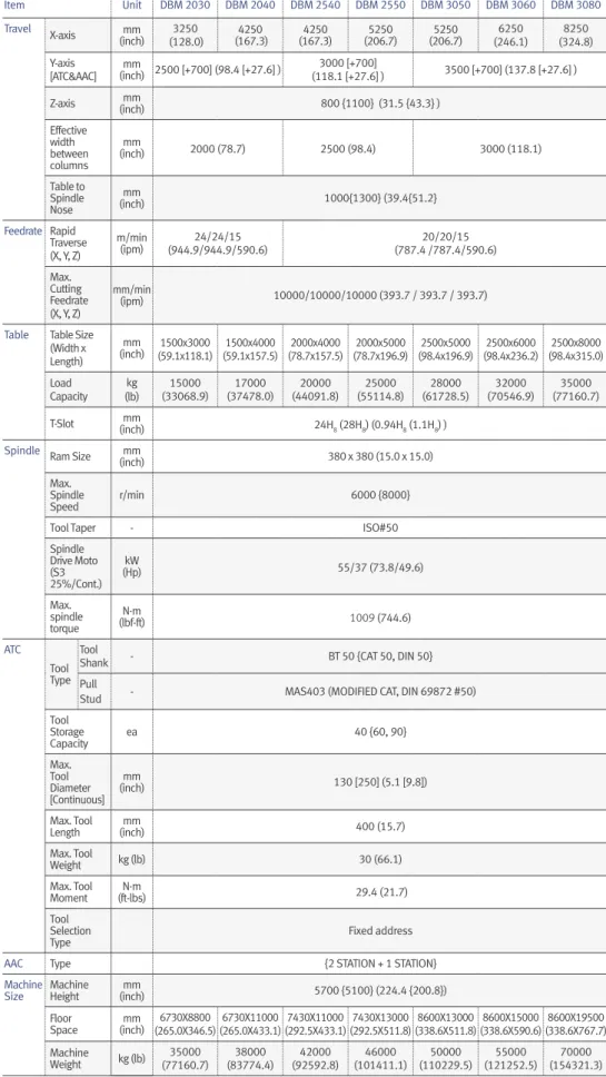
Item Unit DBM 2030 DBM 2040 DBM 2540 DBM 2550 DBM 3050 DBM 3060 DBM 3080 Travel X-axis mm (inch) (128.0) 3250 (167.3)4250 (167.3)4250 (206.7)5250 (206.7)5250 (246.1) 6250 (324.8) 8250 Y-axis [ATC&AAC] (inch) 2500 [+700] (98.4 [+27.6] )mm (118.1 [+27.6] )3000 [+700] 3500 [+700] (137.8 [+27.6] ) Z-axis (inch)mm 800 {1100} (31.5 {43.3} ) Effective width between columns mm (inch) 2000 (78.7) 2500 (98.4) 3000 (118.1) Table to Spindle Nose mm (inch) 1000{1300} (39.4{51.2} Feedrate Rapid Traverse (X, Y, Z) m/min (ipm) (944.9/944.9/590.6)24/24/15 (787.4 /787.4/590.6)20/20/15 Max. Cutting Feedrate (X, Y, Z) mm/min (ipm) 10000/10000/10000 (393.7 / 393.7 / 393.7)Table Table Size (Width x Length) mm (inch) (59.1x118.1) 1500x3000 1500x4000 (59.1x157.5) 2000x4000 (78.7x157.5) 2000x5000 (78.7x196.9) 2500x5000 (98.4x196.9) 2500x6000 (98.4x236.2) 2500x8000 (98.4x315.0) Load Capacity kg (lb) (33068.9)15000 (37478.0)17000 (44091.8)20000 (55114.8)25000 (61728.5)28000 (70546.9)32000 (77160.7)35000 T-Slot (inch)mm 24H8 (28H8) (0.94H8 (1.1H8) )
Spindle Ram Size mm
(inch) 380 x 380 (15.0 x 15.0)
Max. Spindle
Speed r/min 6000 {8000}
Tool Taper - ISO#50
Spindle Drive Moto (S3 25%/Cont.) kW (Hp) 55/37 (73.8/49.6) Max. spindle torque N·m (lbf-ft) 1009 (744.6) ATC Tool Type Tool
Shank - BT 50 {CAT 50, DIN 50}
Pull
Stud - MAS403 (MODIFIED CAT, DIN 69872 #50)
Tool Storage Capacity ea 40 {60, 90} Max. Tool Diameter [Continuous] mm (inch) 130 [250] (5.1 [9.8]) Max. Tool Length (inch)mm 400 (15.7) Max. Tool Weight kg (lb) 30 (66.1) Max. Tool Moment (ft-lbs)N·m 29.4 (21.7) Tool Selection
Type Fixed address
AAC Type {2 STATION + 1 STATION}
Machine
Size Machine Height (inch)mm 5700 {5100} (224.4 {200.8}) Floor Space (inch)mm (265.0X346.5) 6730X8800 6730X11000 (265.0X433.1) 7430X11000 (292.5X433.1) 7430X13000 (292.5X511.8) 8600X13000 (338.6X511.8) 8600X15000 (338.6X590.6) 8600X19500 (338.6X767.7) Machine Weight kg (lb) (77160.7)35000 38000 (83774.4) 42000 (92592.8) 46000 (101411.1) 50000 (110229.5) 55000 (121252.5) 70000 (154321.3)
{ } : optional * 12K Extension Head Attachment TSC not available
Product Preview Basic information Broad Range of Machining Capabilities High-Precision, High-Speed Mold Machining Performance Convenient Machining Functions Machine Information Standard/Optional Specifications Machine Specifications Customer Support
Standard Optional X N/A
NC Unit Specifications
- Axes control
- Interpolation & feed function - Spindle & M-code function - Tool function
- Programming and editing function - Others (operation, setting &
display, etc)
- Frame reference function
No.Classification Item Spec. FANUC i PLUSDOOSAN FANUC 31i
1
Axes control
Controlled axes 3 ( X,Y,Z)
2 Additional controlled axes 6 axes in total
3 Simultaneously controlled axes Positioning(G00)/Linear interpolation(G01) : 3 axes
Circular interpolation(G02, G03) : 2 axes
4 Backlash compensation
5 Emergency stop / overtravel
6 HRV control
7 Least command increment 0.001 mm / 0.0001"
8 Least input increment 0.001 mm / 0.0001"
9 Machine lock all axes
10 Mirror image Reverse axis movement (setting screen and M - function)
11 Stored pitch error compensation Pitch error offset compensation for each axis
12 Interpolation type pitch error compensation
13 Stored stroke check1 Overtraval controlled by software
14 Absolute pulse coder
15 Position switch
16
Interpolation & feed function
2nd reference point return G30
17 3rd/4th reference return G30P3/P4
18 Circular interpolation G02, G03
19 Cylinderical interpolation G07.1
20 Linear interpolation G01
21 Helical interpolation
22 Bell-type acceleration/deceleration before look ahead interpolation
23 Polar coordinate interpolation G12.1 / G13.1 X
24 Exponential interpolation X
25 Involute interpolation X
26 Smooth backlash compensation
27 Dwel G04
28 Exact stop check G09, G61 (mode)
29 Feed per minute mm / min
30 Feedrate override 0 - 200 % (10% unit)
31 Automatic corner override G62
32 Automatic corner deceleration
33 Cutting feedrate clamp
34 Rapid traverse bell-shaped acceleration/deceleration
35 3-dimensional manual feed
36 Manual handle feed 1 unit X
37 Manual handle feed 2/3 unit Max. 3unit 1 unit
38 Manual handle feed rate x1, x10, x100 (per pulse)
39 Manual handle interruption
40 Manual handle retrace
41 Override cancel M48 / M49
42 Positioning G00
43 Rapid traverse override F0 (fine feed), 25 / 50 / 100 %
44 Reference point return G27, G28, G29
45 Skip function G31
46 AICC II 200 BLOCK X
47 High-speed processing 600 BLOCK X
48 Look-ahead blocks expansion 1000 BLOCK X
49 DSQ I AICC II (200block) + Machining condition selection function
50 DSQ II AICC II (200block) + Machining condition selection function + Data server(1GB) X
51 DSQ III AICC II with high speed processing (600block) + Machining condition selection function + Data server(1GB) X 53
Spindle & M-code function
M- code function
54 Spindle orientation M 3 digits
55 Spindle speed command S5 digits
56 Spindle speed override 10 - 150 (10% increments)
57 Retraction for rigid tapping
58 Rigid tapping G84, G74
59
Tool function
Tool nose radius compensation (Cutter compensation C) G40, G41, G42
60 Number of tool offsets 64 ea X
61 Number of tool offsets 200 ea X
62 Number of tool offsets 400 ea
63 Number of tool offsets 499 / 999 / 2000 ea X
64 Tool length compensation G43, G44, G49
65 Tool life management
66 Addition of tool pairs for tool life management
67 Tool number command T3 digits
68 Tool offset memory C Geometry / Wear and Length / Radius offset memory
69 Tool offset G45 - G48
NC Unit Specifications
FANUC
Standard Optional X N/A
No.Classification Item Spec. DOOSAN FANUC i PLUS FANUC 31i 69 Programming and editing function
Absolute / Incremental programming G90 / G91
70 Automatic Coordinate system setting
71 Background editing
72 Canned cycle G73, G74, G76, G80 - G89, G99
73 Circular interpolation by radius programming
74 Custom macro
75 Addition of custom macro common variables #100 - #199, #500 - #999
76 Macro executor
77 Decimal point input
78 Extended part program editing
79 Part program storage 1MB(2,560m)
80 Part program storage 2MB(5,120m)
81 Part program storage 4MB(1,0240m)
82 Part program storage 8MB(2,0480m)
83 Inch/metric conversion G20 / G21
83 Label skip
84 Maximum commandable value ±99999.999mm(±9999.9999 inch)
85 No. of Registered programs 1000 ea
86 No. of Registered programs 4000 ea X
87 Optional block skip 9 BLOCK
88 Optional stop M01
89 Program file name 32 characters
90 Program number O4-digits X
91 Sequence number N 8-digit
92 Playback function
93 Program protect
94 Program stop / end M00 / M02, M30
95 Programmable data input Tool offset and work offset are entered by G10, G11
96 Sub program Up to 10 nesting
97 Tape code ISO / EIA Automatic discrimination
98 Thread cutting
99 Program restart
100 Workpiece coordinate system G52 - G59
101 Addition of workpiece coordinate system G54.1 P1 - 48 (48 pairs)
102 Addition of workpiece coordinate system G54.1 P1 - 300 (300 pairs)
103 Coordinate system rotation G68, G69
104 Extended part program editing
105 Optional angle chamfering . Corner R
106
Others (Operation, setting & Display, etc)
Alarm display
107 Alarm history display
108 Actual cutting speed display
109 Clock function
110 Coordinate system rotation G68,G69
111 Cycle start / Feed hold
112 Display of PMC alarm message Message display when PMC alarm occurred
113 Dry run
114 Embeded Ethernet ( Ethernet )
115 Graphic display Tool path drawing
116 Help function
117 Loadmeter display
118 MDI / DISPLAY unit 15" Color LCD, Keyboard for data input, soft-keys
119 Memory card interface
120 I/O interface RS - 232C
121 USB memory interface Only Data Read & Write
122 Operation functions Tape / Memory / MDI / Manual
123 Operation history display
124 DNC operation with memory card only FANUC
125 Optional angle chamfering / corner R
126 Run hour and part number display
127 Search function Sequence NO. / Program NO.
128 Self - diagnostic function
129 Servo setting screen
130 Single block
131 External data input
132 Stored stroke check 2, 3
133 Multi language display
134 Cs contouring control
135 CNC screen display
136 CNC screen dual display function
137 Reader/Puncher interface (for 2ch) Note1)
138 Multi spindle control Note2) X
139 Extended Spindle orientation Note2)
140 Extended spindle output switching function Note2)
141 Chopping function G81.1 X
142 High speed skip function
143 Polar coordinate command G15 / G16
144 Programmable mirror image G50.1 / G51.1
145 Scaling G50, G51
146 Single direction positioning G60
147 Fast Data server with1GB PCMCIA card
148 Fast Ethernet
149 3-dimensional tool compensation X
150 Tape format for FS15
151 Figure copying G72.1, G72.2
152 Machining time stamp function
153 EZ Guide I with 15" Color TFT
- Doosan machine tools Conversational Programming Solution
- When the EZ Guide i is used, the Dynamic graphic display cannot application
154 Dynamic graphic display (with 15" Color TFT LCD) - Machining profile drawing.- When the EZ Guide i is used, the Dynamic graphic display cannot application
Product Preview Basic information Broad Range of Machining Capabilities High-Precision, High-Speed Mold Machining Performance Convenient Machining Functions Machine Information Standard/Optional Specifications Machine Specifications Customer Support
Doosan Machine Tools’ Global Network, Responding to Customer’s Needs nearby, Anytime, Anywhere
Doosan machine tools provides a system-based professional support service before and after the machine tool sale by responding quickly and
efficiently to customers’ demands. By supplying spare parts, product training, field service and technical support, we can provide top class
support to our customers around the world.
Responding to Customers
Anytime, Anywhere
We help customers to achieve success by providing a variety of professional services from pre-sales consultancy to post-sales support.
Customer Support Service
Supplying Parts
• Supplying a wide range of original
Doosan spare parts
• Parts repair service
Field Services
• On site service
• Machine installation and testing
• Scheduled preventive maintenance
• Machine repair
Technical Support
• Supports machining methods and
technology
• Responds to technical queries
• Provides technical consultancy
Training
• Programming / machine setup
and operation
• Electrical and mechanical
maintenance
• Applications engineering
Changwon Factory Head Office AMERICA EUROPE CHINA (Yantai) CHINA (Shanghai) INDIA4
Global Sales and Service Support Network
Sales Support, Service Support, Parts Support
Corporations
200
Service Post51
Technical Centersver.
EN 200923 SU
Head Office
22F T Tower, 30, Sowol-ro 2-gil, Jung-gu,
Seoul, Korea, 04637
Tel
+82-2-6972-0370 / 0350
Fax
+82-2-6972-0400
Doosan Machine Tools America
19A Chapin Rd., Pine Brook, NJ 07058, U.S.A.
Tel
+1-973-618-2500
Fax
+1-973-618-2501
Doosan Machine Tools Europe
Emdener Strasse 24, D-41540 Dormagen,
Germany
Tel
+49-2133-5067-100
Fax
+49-2133-5067-111
Doosan Machine Tools India
No.82, Jakkuar Village, Yelahanka Hobil,
Bangalore-560064
Tel
+ 91-80-2205-6900
[email protected]
Doosan Machine Tools China
Room 101,201,301, Building 39 Xinzhuan
Highway No.258 Songjiang District,China
Shanghai(201612)
Tel
+86 21-5445-1155
Fax
+86 21-6405-1472
*For more details, please contact Doosan Machine Tools.
*The specifications and information above-mentioned may be changed without prior notice.
* Doosan Machine Tools Co., Ltd. is a subsidiary of MBK Partners. The trademark is used under a licensing agreement with Doosan Corporation, the registered trademark holder.
There is a high risk or fire when using non-water-soluble cutting fluids, processing flammable materials, neglecting use coolants and modifying the machine without the consent of the manufacturer. Please check the SAFETY GUIDANCE carefully before using the machine.
Fire Safety Precautions