DigitalCommons@University of Nebraska - Lincoln
DigitalCommons@University of Nebraska - Lincoln
Theses, Dissertations, and Student Researchfrom Electrical & Computer Engineering Electrical & Computer Engineering, Department of
Spring 4-17-2013
Distributed Multi-object Tracking with Multi-camera Systems
Distributed Multi-object Tracking with Multi-camera Systems
Composed of Overlapping and Non-overlapping Cameras
Composed of Overlapping and Non-overlapping Cameras
Youlu Wang
University of Nebraska-Lincoln, [email protected]
Follow this and additional works at: https://digitalcommons.unl.edu/elecengtheses
Part of the Electrical and Computer Engineering Commons
Wang, Youlu, "Distributed Multi-object Tracking with Multi-camera Systems Composed of Overlapping and Non-overlapping Cameras" (2013). Theses, Dissertations, and Student Research from Electrical &
Computer Engineering. 47.
https://digitalcommons.unl.edu/elecengtheses/47
This Article is brought to you for free and open access by the Electrical & Computer Engineering, Department of at DigitalCommons@University of Nebraska - Lincoln. It has been accepted for inclusion in Theses, Dissertations, and Student Research from Electrical & Computer Engineering by an authorized administrator of
COMPOSED OF OVERLAPPING AND NON-OVERLAPPING CAMERAS
by
Youlu Wang
A DISSERTATION
Presented to the Faculty of
The Graduate College at the University of Nebraska In Partial Fulfilment of Requirements
For the Degree of Doctor of Philosophy
Major: Electrical Engineering
Under the Supervision of Professors Sina Balkır and Senem Velipasalar
Lincoln, Nebraska May, 2013
COMPOSED OF OVERLAPPING AND NON-OVERLAPPING CAMERAS
Youlu Wang, Ph.D. University of Nebraska, 2013
Adviser: Sina Balkır and Senem Velipasalar
Multiple cameras have been used to improve the coverage and accuracy of visual surveillance systems. Nowadays, there are estimated 30 million surveillance cameras deployed in the United States. The large amount of video data generated by cameras necessitate automatic activity analysis, and automatic object detection and tracking are essential steps before any activity/event analysis. Most work on automatic tracking of objects across multiple camera views has considered systems that rely on a back-end server to process video inputs from multiple cameras. In this dissertation, we propose distributed camera systems in peer-to-peer communication. Each camera in the proposed systems performs object detection and tracking individually and only exchanges a small amount of data for consistent labeling. With the lightweight and robust algorithms running in each camera, the systems are capable of tracking multiple objects in a real-time manner.
The cameras in the system may have overlapping or non-overlapping views. With par-tially overlapping views, the object labels can be handed off between cameras based on geometric relations. Most camera systems with overlapping views attach cameras to PCs and communicate via Ethernet, which hinders the flexibility and scalability. With the ad-vances in VLSI technology, smart cameras have been introduced. A smart camera not only captures images, but also includes a processor, memory and communication interface making it a stand-alone unit. We first present a wireless embedded smart camera system for coop-erative object tracking and detection of composite events. Each camera is a CITRIC mote
boards. Power consumption of the proposed system is analyzed based on the measurements of operating currents for different scenarios.
On the other hand, in wide-area tracking applications, it is not always realistic to assume that all the cameras in the system have overlapping fields of view. Tracking across non-overlapping views present more challenges due to lack of spatial continuity. To address this problem, we present another distributed camera system based on a probabilistic Petri Net framework. We combine appearance features of objects as well as the travel-time evidence for target matching and consistent labeling across disjoint camera views. Multiple features are combined by adaptive weights, which are assigned based on the reliability of the features and updated online. We employ a probabilistic Petri Net to account for the uncertainties of the vision algorithms and to incorporate the available domain knowledge.
Synchronization is another important problem for multi-camera systems, because it is essential to have the precise relevance between the video data captured by different cameras. We present a computationally efficient and robust method for temporally calibrating video sequences from unsynchronized cameras. As opposed to expensive hardware-based synchro-nization methods, our algorithm is solely based on video processing. This algorithm is to match and align the object trajectories using the Longest Consecutive Common Subsequence, and thus to recover the frame offset between video sequences.
With the increasing number of cameras in the system, cost and flexibility are important factors to consider. The cost of each camera node increases with the increasing resolution of the image sensor. A possible way of employing low-cost low-resolution sensors to achieve higher resolution images is presented. In this system, four embedded cameras with low-resolution customized sensors are tiled in different arrangements. With the customized CMOS imager, we perform edge and motion detection on the focal plane, then stitch the four edge images together to get a higher-resolution edge map.
ACKNOWLEDGMENTS
First and foremost, I would like to express my deepest gratitude to my advisor Professor Senem Velipasalar for her patience, wisdom, enthusiasm, perseverance, encouragement and understanding. She always conveys a strong motivation and passion in regard to research and academia. She sets a high standard as a researcher and a professor, that I look up to but may never be able to reach. She teaches me why “research” is called “research” — because we have to keep failing and “re”-search for new solutions. And every time when I fail, she encourages me not to give up and helps me to find a new way out. It would not have been possible to accomplish this dissertation without her tremendous help and guidance throughout the whole process. As both being female researchers, she always understands my concerns and supports my needs without any hesitation. I cannot find enough words to express my thankfulness.
I would like to thank Professors Mustafa Cenk Gursoy, Mehmet Can Vuran and Michael W. Hoffman for serving on my doctoral committee, and for their generous comments and suggestions to make my dissertation much better. I also thank them for the impressive and enjoyable lectures they teach. Their lectures have been great resources to broaden my mind and inspire my research.
I want to show my special thanks to Professor Sina Balkır for being the co-chair of my committee, for granting me this great opportunity of being a student in UNL at the beginning and helping me to finish my PhD study at the end. It is the best of luck to have the kind support of him.
I share the credit of my work with my fellow graduate students Mauricio Casares, Alvaro Pinto, Li He and Zhe Zhang. They have been working closely with me, and share all their time and thoughts unselfishly. I could not have achieved any of the accomplishments without their efforts. I also thank all my friends in Lincoln. Their friendship brings me a lot of joy
and laughter, making my life in Lincoln unforgettable forever.
Last but not the least, I would like to thank my family — my grandfather Xin Wang, my grandmother Qihua Xie, my father Xuan Wang, my mother Guanzhen Li, my husband Xinwang Zhang and my son Shi Wang — for their unconditional love. Although my grand-father has leaved us and didn’t have the chance to see this dissertation, I am sure he would be happy for what I have achieved today. This dissertation is dedicated to them.
Contents
Contents vi
List of Figures ix
List of Tables xiii
I Introduction
1
1 Introduction 2
1.1 Background . . . 2
1.2 Related Work . . . 6
1.3 Contributions and Dissertation Outline . . . 14
1.4 Publications . . . 19
II Object Tracking and Event Detection with Wireless
Em-bedded Smart Cameras
22
2 Embedded Smart Cameras and Lightweight Vision Algorithms 23 2.1 The Wireless Embedded Smart Camera Platform . . . 242.3 Fast Blob Forming and Connected Component Labeling . . . 28
2.4 Object Tracking Algorithm . . . 30
2.5 Conclusions . . . 33
3 Cooperative Object Tracking and Event Detection 35 3.1 Consistent Labeling . . . 36
3.2 Composite and Spatio-temporal Event Detection . . . 39
3.3 Communication between Cameras . . . 42
3.4 Conclusions . . . 51
4 Power Analysis and Experimental Results 53 4.1 Power Consumption and Performance Analysis . . . 54
4.2 Object Tracking and Event Detection Experimental Results . . . 66
4.3 Conclusions . . . 77
III Distributed Object Tracking with Non-overlapping Camera
Views
79
5 Real-time Distributed Tracking with Non-Overlapping Camera Views 80 5.1 Introduction . . . 805.2 Object Tracking across Non-overlapping Cameras . . . 81
5.3 Experimental Results . . . 86
5.4 Conclusions . . . 89
6 A More Robust Algorithm for Object Re-identification 91 6.1 Multi-feature Object Matching . . . 92
6.2 Adaptive Parameter Updating . . . 99
7 A Petri Net-based Framework for Tracking and Object Matching 104
7.1 Introduction . . . 104
7.2 Petri Nets . . . 107
7.3 A Petri Net-based Framework for Tracking and Object Matching . . . 111
7.4 Vehicle Tracking Experiments . . . 114
7.5 People Tracking Experiment Incorporating New Domain Knowledge . . . 123
7.6 Discussions of Scalability and Domain Knowledge . . . 128
7.7 Conclusions . . . 132
IV Other Work on Multi-camera Systems
134
8 Frame-Level Temporal Calibration of Unsynchronized Cameras 135 8.1 Introduction . . . 1358.2 LCS and LCCS . . . 137
8.3 Trajectory Alignment Using LCCS . . . 138
8.4 Experimental Results . . . 145
8.5 Conclusions . . . 147
9 Edge And Motion Detection On Focal Plane 148 9.1 Introduction . . . 148
9.2 The Low-Resolution Embedded Smart Camera . . . 151
9.3 Edge Detection on the Focal Plane . . . 153
9.4 Tiling of the Multiple Embedded Smart Cameras . . . 160
9.5 Experimental Results . . . 164
9.6 Conclusions . . . 165
List of Figures
2.1 The wireless embedded smart camera platform employed in the proposed system. 24
2.2 Example of resolving a merge. . . 32
3.1 Recovery of the FOV lines . . . 36
3.2 Packet Format of Wireless and Serial Communication. . . 44
3.3 The process of request sending and reply receiving between two cameras. . . 45
4.1 Amount of the current drawn by the camera board over time while tracking one, two and three remote-controlled cars and when using: (a) multi-pass connected component labeling algorithm and (b) single-pass blob forming algorithm. . . . 55
4.2 Operating currents of the camera board while tracking one larger car and two smaller cars, and when using: (a) multi-pass connected component labeling algo-rithm and (b) single-pass blob forming algoalgo-rithm. . . 58
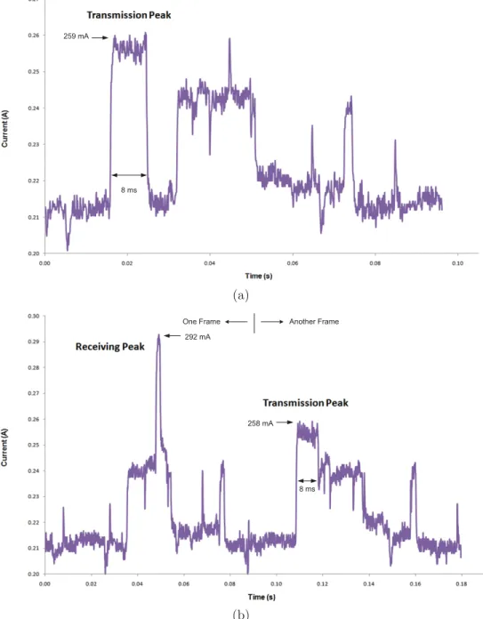
4.3 Operating current of the camera when (a) transmitting a new label request, and (b) when receiving a new label request and transmitting a new label reply. . . . 60
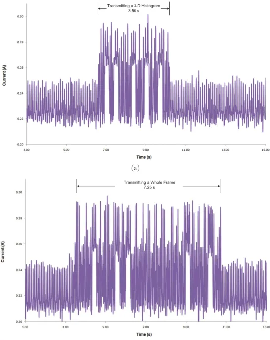
4.4 Current amounts drawn over time when transmitting (a) a packet containing color histogram of a tracked object (b) a whole image. . . 63
4.5 Average power consumed by the camera during different portions of processing a frame(with and without TelosB) . . . 64
4.6 Average power consumed by the camera during different portions of processing a frame while tracking two cars and transmitting or receiving a packet . . . 65 4.7 The three-camera setup. . . 66 4.8 Two cars being tracked across different camera views with consistent labels. . . 67 4.9 A car being occluded in the second camera view. . . 69 4.10 An event scenario composed of two primitive events spanning two different camera
views. . . 70 4.11 An event scenario composed of three primitive events spanning two different
cam-era views. . . 71 4.12 An event scenario composed of four primitive events spanning two different
cam-era views. . . 72 4.13 An event scenario composed of three primitive events spanning three different
camera views. . . 75 4.14 An event scenario composed of four primitive events spanning three different
camera views. . . 76 5.1 The work flow of object matching in one camera . . . 83 5.2 Two people enter the view of the right camera from the same side (a) Person 11
is being tracked by the left camera (b) another person enters the right camera’s view before Person 11 does, and gets the label 20 (c) Person 11 enters the right camera’s view and is assigned the correct label. . . 87 5.3 Two people tracked by the left camera and one tracked by the right camera
(a-b),(c-d) People with labels 11 and 12 are tracked by the left camera; (e) a person enters the right camera view and is assigned a temporary label 0; (f) new person is assigned the correct label 11. . . 88
5.4 Two people enter at the opposite side of the right camera (a-b) Person 11 is being tracked by the left camera; (c) another person enters the right cameras view at the right side and is assigned label 20; (d) person 11 enters the right cameras view and is assigned a temporary label 0; (e) person 20 and person 0 merge during frames 5 to 7; (f) after the split, person 0 is assigned the correct label 11 by
matching process. . . 89
6.1 Example of the angle correction for texture descriptors. . . 94
6.2 An example of LBP operator. . . 95
6.3 Example of the different size factors of the cars in different lanes. . . 97
7.1 Examples of Petri Nets . . . 108
7.2 A probabilistic Petri Net for car pickup activity [74] . . . 110
7.3 Probabilistic Petri Net for tracking and object matching. . . 112
7.4 Views of the three cameras. . . 115
7.5 A scenario involving white and light gray cars. . . 116
7.6 A scenario involving cars with red colors. . . 116
7.7 Gaussian Mixture Model of the travel time between Camera 1 and Camera 3. . 117
7.8 Results of weight training. . . 118
7.9 Example of matched cars. . . 119
7.10 Example of handling new and left cars. . . 119
7.11 Example of matched cars with similar features. . . 120
7.12 Probabilistic Petri Net for people tracking and matching. . . 124
7.13 Views of the three cameras. . . 125
7.14 An example of the saved object. . . 127
7.16 The Comparison of amount of data transmitted between a server-based system and our peer-to-peer system. . . 129 7.17 The flowchart for the users’ input of domain knowledge. . . 131 8.1 Examples of matched trajectories in two cameras . . . 146 9.1 (a) the embedded smart camera, (b) the board and the CMOS imager used in
this camera. . . 151 9.2 Three levels of processing obtained by the smart camera architecture [129]. . . . 152 9.3 Diagram of the column-level architecture [131]. . . 154 9.4 The diagram of the edge detection circuit [131]. . . 155 9.5 The flow diagram of pixel selection [131]. . . 156 9.6 Comparison of the detected edges on the focal plane with the full edge strength
calculation and west-edge strength only: (a)(b)(c) Original images, (a1)(b1)(c1) edges obtained with the proposed full-edge strength method, (a2)(b2)(c2) edges obtained with west-edge strength only. . . 158 9.7 Edge-based detection of a moving bottle: (a) An example frame, (b)(c)(d) edges
of the moving object at different instances. . . 159 9.8 Edge-based detection of a moving mouse:a) An example frame, (b)(c)(d) edges
of the moving mouse at different instances. . . 160 9.9 (a) 1×4 array and (b) 2×2 array of our smart cameras. . . 160 9.10 Automatically stitched higher-resolution images and edge maps obtained on the
focal plane. . . 162 9.11 Higher-resolution images and edge maps obtained in the focal plane with the 2×2
List of Tables
2.1 Data contained in a tracker . . . 33 4.1 Power and energy consumption for different scenarios when using the multi-pass
connected component labeling . . . 56 4.2 Power and energy consumption for different scenarios when using the single-pass
blob forming algorithm . . . 56 7.1 Definition of a Petri Net . . . 109 8.1 Pseudo code for the LCCS-based trajectory matching . . . 143 8.2 The frame offsets obtained after the confidence check with the proposed method
Part I
Chapter 1
Introduction
1.1
Background
Cameras are widely employed in military and commercial applications, and public trans-portation scenarios for purposes of surveillance, statistics gathering, and traffic flow mon-itoring. Nowadays, there are estimated 30 million surveillance cameras deployed in the United States. The scale and complexity of camera systems have been continuously increas-ing to have better coverage and accuracy. The large amount of video data generated by multi-camera systems necessitates automatic activity analysis.
1.1.1
Overview of Object Tracking
Instead of viewing the recorded videos and detecting objects by human eyes, automatically detecting foreground objects is the first step of automatic video analysis. Existing methods for foreground object detection can be generally classified into two categories: temporal difference methods[42, 43], and background subtraction methods[3, 47, 39, 14, 19, 38, 30, 40]. Temporal difference methods subtract two consecutive frames and then apply a threshold to the output. The pixels with a difference higher than the threshold are considered foreground
pixels. These methods do not need to deal with the problem caused by the background changing over time. However, they cannot detect all the pixels of a moving object, as the overlapping part of the objects will be removed. On the other hand, background subtraction methods build a model of the background and subtract this from the current frame to detect the foreground pixels in the scene. The background model is usually required to be updated over time and adapt to changes in the environment. Most of the state-of-the-art tracking algorithms for fixed cameras employ the background subtraction methods [9].
After the foreground pixels are detected, they are represented in a binary frame, wherein the 1s indicate the foreground pixels and 0s indicate the background pixels. The foreground pixels need to be grouped into blobs with a certain connected component analysis method. Each blob corresponds to an object. For each detected object, a label is assigned and a tracker with a suitable representation of the object is formed. The purpose of the tracker is to generate the trajectory of the object by locating its position in every frame. The representation of the object normally contains the location of the object and the descriptors of some features, such as color, shape, size and texture. Then additional analysis can be performed based on the object trajectories to recognize their behaviors. In visual surveillance, this analysis often refers to detecting suspicious activities or events of interest [9].
Object tracking with multi-camera systems can be desired for varying scenarios, such as monitoring smaller areas with overlapping views, or tracking objects across wide areas with disjoint camera views. Using multiple cameras with overlapping views fuses the information of objects from different angles. This helps to resolve tracking difficulties caused by occlu-sion and crowdedness, and thus enhance the accuracy. With partially overlapping views, the consistent labels of the tracked objects can be handed off from one camera to another based on the geometric relations. Thus, a larger area can be monitored with multiple cooperative cameras. On the other hand, in wide-area tracking applications, it is not always realistic to assume that all cameras will have overlapping fields of view. Tracking across non-overlapping
views presents more challenges due to lack of spatial continuity, and the difficulty of recov-ering geometric relations. To re-identify the objects and achieve consistent labeling across disjoint views, more features and more complex models are needed.
1.1.2
Object Tracking with Distributed Cameras
Most work on autonomous tracking of objects across multiple camera views has considered systems that rely on a back-end server to process video inputs from multiple cameras. Yuan et al. [48], Collins et al. [7, 8], Nguyen et al. [28], Lo et al. [26] and Krumm et al. [23] present systems where a server/controller performs the coordination and integration of the data from individual nodes. But, these systems have a bandwidth scaling problem, since the central server can quickly become overloaded with the aggregate sum of messages/requests from the nodes. Also, the server is a single point of failure for the whole system. In addition, server-based systems are not practical in many realistic environments, and have high installation costs. These problems of server-based systems necessitate the use of peer-to-peer (P2P) systems, where individual nodes communicate with each other without going through a centralized server.
More recently, multi-camera systems communicating in a P2P fashion have been intro-duced. Each camera node has its own processing power, and is able to detect and track objects by itself. Camera nodes cooperate to solve the consistent labeling problems, by ex-changing object labels, and retrieve the locations of the occluded objects. Thus, the amount of data that need to be exchanged can be reduced significantly. Also each node has the ability to initiate a request, produce a reply, and make its own decisions. This removes the necessity of a central server and decreases the required communication bandwidth. Therefore, these systems are usually capable of performing object tracking in real time.
and communication is performed over wired links [1, 15, 44]. These systems are assumed to be wall-powered and have bulky sizes. These affect the flexibility of camera installation as well as mobility, and incur significant costs, especially when more cameras are desired nowadays for wider areas and more complicated scenarios.
1.1.3
Object Tracking with Embedded Smart Cameras
With the advances in VLSI technology and embedded computing, smart cameras have been introduced, and it has now become viable to install many spatially-distributed cameras interconnected by wireless links. A smart camera not only captures images, but also includes a processor, memory and communication interface making it a stand-alone unit. Yet, many system- and algorithm-wise challenges remain to be addressed to have operational wireless smart-camera networks (Wi-SCaNs).
Embedded smart cameras have limited processing power, memory, energy and bandwidth. Although many methods have been introduced for robust foreground object detection and tracking, much less attention has been paid to the memory requirement and the portability of these algorithms to an embedded processor. Due to limited resources, most of the embedded smart camera systems [6, 20, 33] use relatively simple and sometimes less robust methods such as temporal difference and running average. Robust and feasible algorithms which require less memory, less computation and are optimized for the hardware architecture, need to be developed.
Another challenge is related to the wireless communication and data exchange between embedded cameras. Frequent transfer of large-sized data consumes more energy and incurs more communication delay. In many systems, communication is 100 to 1000 times more expensive in energy than computation [34]. Unlike wall-powered multiple cameras connected to CPUs, and communicating via Ethernet, wireless smart cameras have much less memory
for storage, limited bandwidth and limited power supply. Due to these constraints, it is not viable to transfer or save every frame or every object trajectory. The tracking algorithms in each camera should be able to process and abstract the raw data as much as possible, and should only require minimal amount of information from other cameras.
Moreover, instead of transferring or saving every frame or every trajectory, there should be a mechanism to detect events of interest. Events of interest can be defined beforehand, and simpler events can be combined in a sequence to define semantically higher-level and composite events. Moreover, event scenarios can span multiple camera views, which make the definition of more complex events possible. Cameras communicate with each other about the portions of a scenario to detect an event that spans different camera views.
1.2
Related Work
1.2.1
Related Work on Multi-camera Multi-object Tracking
1.2.1.1 Multi-camera Tracking with Overlapping Camera Views
In a multi-camera setup, usually every single camera has the ability of tracking the objects individually. Cameras collaborate with each other to track objects consistently for longer pe-riods of time, or resolve merge/split problems caused by objects interacting. Object tracking with partially overlapping camera views has been researched extensively in the last decade [44, 100, 76, 95, 79, 77, 69, 62, 71, 68, 8, 10, 71].
With partially overlapping camera views, the geometric relationship between the cameras can be recovered and utilized as an important cue. Converting all coordinates into a common 3D coordinate system is a popular approach to relate the objects across multiple cameras [76, 77, 8, 10, 23, 62, 119]. This approach requires the cameras to be fully calibrated, which is expensive and sometimes inconvenient. With all objects moving in a common 3D space, a
tracking algorithm similar to 2D tracking can be adopted, such as Kalman filter [10, 76] or particle filter [77]. Most of the proposed systems have some degree of distributed processing, wherein each camera has the ability of object detection/tracking. But at the end, they still need a central processing unit to integrate the simplified data from the sensors, convert them into the common 3D space and make the decisions.
Blanco et al. [77] argue that 3D tracking based on partially erroneous 2D tracks are likely to fail when handling multiple-people interaction. To address this problem, they propose a Bayesian framework for combining 2D low-level cues from multiple cameras directly into the 3D world through 3D Particle Filters, instead of combining the tracking results from each camera. Dockstader et al. [10] propose a Kalman filter-based approach in 3D space, targeted at resolving the problem of occlusion and human interacting. The corrected state vectors from each view provide input observations to a Bayesian belief network, in the central processor. Then, a layer of Kalman filtering is employed to update the 3D state estimates. Collins et al. [8] also adopt a distributed-processing and central-decision-making framework. The central control unit uses a 3D geometric site model to integrate symbolic object trajectory information accumulated by each sensor node, and presents the results to the user on a map-based graphical user interface. The feasibility of real-time processing is demonstrated.
Another useful and reasonable assumption for most tracking scenarios is that all of the objects moving on the same planar ground. With the common ground plane assumption, a homography matrix between every two adjacent cameras can be computed, which is easier than full calibration [44, 79, 69]. Khan and Shah [69] use a planar homography constraint that combines foreground likelihood information from different views to resolve occlusions and determine ground plane locations of people. The homography constraint indicates that only the pixels of people’s feet (on the ground) will consistently warp to foreground regions in every view. The field-of-view (FOV) lines [95] is also introduced by Khan and Shah so
that the labels can be handed off when the objects enter other cameras’ fields of view. In this way, the consistent labeling is achieved. Calderara et al. [79] propose a method to detect the FOV lines automatically. Kayumbi et al. [24] propose a registration algorithm based a statistical homography estimation. Then, a mosaic scene is generated with the registration of the trajectories from multiple camera views.
There are other works that use feature matching approaches to avoid camera calibration. Moller et al. [100] propose a calibration-free method that use color histogram matching based on the mean shift[12] tracking algorithm. But a coarse knowledge of the transfer points between two camera views is still required. Cai et al. [68] employ multivariate normal distributions to model the features, such as location, intensity, and geometric features. The correspondences are established using a set of feature points in a Bayesian probability frame-work. Chang et al. [16] also use Bayesian networks to fuse multiple features for matching subjects between consecutive frames and between multiple camera views. They divide the features into two groups: geometry-based modalities and recognition-based modalities. The former includes epipolar geometry, homography and landmark modalities; the latter includes apparent height and apparent color.
1.2.1.2 Object Tracking across Non-overlapping Camera Views
In wide-area tracking and wide-area surveillance applications, it is not always realistic to assume that all the cameras in the system will have overlapping fields of view. Tracking across disjoint camera views is a more challenging problem due to lack of spatial continuity, and thus having blind regions. In this case, recovering geometric relations may become difficult or infeasible in some scenarios. Feature-based matching is commonly used to solve the object re-identification problem. The cues that are used for object matching typically include appearance features, spatio-temporal evidence or the combination of these two types of information.
Color is one of the most commonly used appearance features. Color information is often represented by color histograms in the RGB or HSV color spaces. HSV is more robust to illumination changes due to its inherent properties. In the HSV color space, the luminance information is placed in the V channel and the chromaticity information is placed in the H (hue) and S (saturation) channels. The separation of the brightness information from the chromaticity reduces the effect of illumination change across difference camera views. In the RGB color space, each channel of Red, Green and Blue stores the brightness informa-tion and color informainforma-tion, which makes RGB histogram more vulnerable to different light condition or camera characteristics. To reduce this effect, Porikli [109] proposed a cross cor-relation model function for pair-wise inter-camera color calibration. The corcor-relation matrix is computed from 1D RGB color histograms, and the model function is obtained from a minimum cost path traced within the matrix. The minimum cost path, which represents a mapping from one camera’s color histogram to that of the other, is obtained by dynamic programming. This method could be computationally expensive. A more efficient way to map the color histograms from one camera to another is calculating the Brightness Transfer Function (BTF). Javed et al. [92] proposed a subspace-based BTF using probabilistic PCA to calculate the subspace of BTFs for a set of known correspondences. Their method relies on a large number of training data with a good range of clothing colors to give an accurate mean BTF (MBTF). Prosser et al. [111] proposed to use cumulative BTF (CBTF) instead of MBTF, which makes use of the available color information from a very sparse training set. A comparison of these two different BTFs can be found in [86], which demonstrates simi-lar behaviors of the two methods when the simple association problem needs to be solved. Their experiments also show that appearance matching relying exclusively on color is not reliable when the scenario is more complicated than simple association, such as new object detection. Cheng et al. [81] proposed to cluster color into a subset of “major colors”, named Major Color Spectrum Histogram Representation (MCSHR). The illumination variations
are compensated by a cumulative histogram equalization. Again, only examples of simple object association are shown in their work. Jeong and Jaynes [93] use UY channels to build a 2D Gaussian Mixture Model and Affine Transformation to find the warping function (color transfer function) between the two models.
In addition to color information, some other appearance features can be combined for object re-identification. For example, height is used together with MCSHR for people track-ing [96]. Texture or edge features are also useful for object matchtrack-ing. Cohen et al. [83] use a covariance matrix-based function integrating color and texture features (gradients) to represent each blob. This method requires a lot of data to be saved for post-processing: each blob’s data for all blobs in all frames need to be saved. Then, the blobs are clustered into trajectories based on the appearance similarity. Cai et al. [78] present a human appearance model by using the region signatures centered at points on the edges of the human objects. The region signatures include the domain color representation and geometric constraints. Their proposed matching method is sequence-to-sequence matching, not frame-to-frame. Similar to [83], their algorithm is computationally expensive, and not intended to be used for real-time processing.
Spatio-temporal information is another important evidence to be considered for object re-identification. One way of using spatio-temporal constraints is predicting the objects’ positions when they are in the blind region. With the assumption of linear motion model, a Kalman filter or a similar mechanism is employed [102, 82]. The positions of the objects could also be inferred based on a common ground assumption, which allows the warping between the cameras’ views using a homography matrix [94]. In [108], expanded triangulation with motion constrains, which assumes linear motion of the objects, is employed for inferring the positions of the objects. The algorithm was only applied to the applications with small gaps between the cameras.
recov-ery of camera network topology, and not the object tracking. Rahimi et al. [112] recover the calibration parameters of the cameras and the targets’ trajectories using MAP estimation. Huang et al. [88] use the transition time as the only evidence to infer the traffic flow status across non-overlapping views. A Gaussian Mixture Model (GMM) of the transition time is built without identifying the object correspondences explicitly. Niu et al. [104] use the ap-pearance model to measure the similarity between disappearing and reappearing trajectories, then detect the possible link between the disjoint views, and estimate the transition time by the weighted cross correlated model. Finally, the non-overlapping network topology is recovered based on the estimated mutual information. Makris et al. [98] build up transition probability models based on transition time between the exits and entries. The topology of the camera networks is recovered by finding the maxima of the cross correlation functions.
To achieve more robust tracking results, spatio-temporal evidence is often combined with multiple appearance features. Javed et al. [91] combine color and travel time in a Bayesian formulation for object association. The best match is found by maximizing the posteriori. Kang et al. [94] use a spatio-temporal Joint Probability Data Association Filter (JPDAF) to formulate a joint probability model encoding objects’ appearance and motion. Two non-overlapping camera views are warped in the reference of a moving camera view and merged into a mosaic. Thus, the object’s motion can be inferred when it is in the gap between two stationary cameras. Chilgunde et al. [82] use position and size changes for object matching. With the assumption of constant velocity model, Kalman filter is used to predict the positions in the blind region. Monari et al. [102] intend to track objects in both overlapping and non-overlapping camera networks. They use 3D positions combined with CIE color space features to perform object association. The 3D positions in the blind region are predicted by a Kalman filter.
Huang and Russell [89] use multiple features for vehicle matching in a Bayesian formula-tion. Different from most of the related work, an association matrix is employed for finding
the best assignments for multiple objects, which travel close to each other. They use mul-tiple features, including lane information, size, color and travel time, to identify vehicles in a traffic application with a 2-camera setup. By adding additional elements of transition probabilities, the possibility of new and missing vehicles is also considered.
1.2.2
Related Work on Embedded Smart Cameras
Common computing platforms for smart cameras are FPGAs, digital signal processors (DSPs), and/or general purpose microprocessors [34]. Different smart camera systems have been introduced recently. Fleck et al. [18] present a network of smart cameras for tracking multiple people. They use commercial IP-based cameras, which consist of a CCD image sensor, a Xilinx FPGA for low-level image processing and a Motorola PowerPC CPU. The system uses color-based particle filters for tracking, but handoff of the objects is based upon a centralized model of the observed scene. Quaritsch et al. [32] employ smart cameras with multiple DSPs for data processing and a mobile agent framework for handling the handoff between cameras. Bramberger et al. [2] present another smart camera architecture de-veloped from common off-the-shelf components, including a CMOS image sensor, multiple Texas Instruments TMS320C64x DSPs for image processing and an Intel XScale IXP425 for network processing. They provide two IP-based external communication: wired Ethernet and wireless GSM/GPRS. While this high-end platform provides sufficient capabilities for image processing, it requires an average power consumption of 35 W.
Wired or IP-based cameras have powerful processing capabilities and relatively high bandwidth for communication. However, they have high power consumption and are larger in size. Many embedded vision platforms, designed for wireless sensor networks, have been developed more recently [36, 20, 33, 17, 22, 13, 25]. The MeshEye platform [20] integrates two low-resolution image sensors and one VGA image sensor. It uses an ARM7 microcontroller
with 55 MHz speed, and has 64 KB RAM and 256 KB flash memory. The Cyclops platform [33] is developed as a sister board for the Mica2 and MicaZ sensor boards, and has a 7.3 MHz-processor. However, in both of these platforms the processing power is still limited. The platform introduced by Kleihorst et al. [22] has an 84 MHz XETAL-II SIMD processor. It has higher resolution but has 128 KB of memory. The CMUcam2 [36] is a low-cost embedded camera with 75 MHz RISC processor and 384 KB SRAM. Due to the limited memory and processing power, only low-level image processing can be performed. The image processing algorithm cannot be modified after deployment since it is integrated in the firmware of the processor. Panoptes platform [17], which hosts a 206 MHz processor and 64 MB of RAM, is developed to generate medium-resolution video at high frame rates. It uses a USB web camera as a video sensor and 802.11 for wireless communications. This platform can perform more sophisticated processes in this high-end architecture, but the high energy consumption of the node limits the lifetime of a wireless application or necessitates wall-powered operation. Rinner et al. [35] presented a comparison of various smart camera platforms.
1.2.3
Related Work on Event Detection
Most of the previous work on event detection focused on detecting a finite set of specific and predefined events [54, 19, 57, 61, 63, 65, 70]. Stringa and Regazzoni [65], and Sacchi and Regazzoni [63] present surveillance systems for the detection of abandoned objects. The system proposed by Haritaoglu et al. [19] can recognize events such as depositing/removing an object or exchanging bags. Rota and Thonnat [61] use two sets of a priori information for video sequence interpretation: contextual information and predefined scenarios. Medioni et al. [57] analyze a set of predefined scenarios in video streams obtained from an airborne moving platform. Watanabe et al. [70] introduce a system for detecting events in which a person enters or leaves a room and/or an object appears or disappears. In addition to
predefined events, research community has worked on unusual event or abnormal behavior detection [50, 52, 55, 59, 60, 38, 66, 72, 73].
However, an event detection system should be generic enough to detect broad range of events by giving users the flexibility to customize their own events with varying complexity. In other words, event definitions should not be predefined and hard-coded into the system, nor should they be limited in number. The system introduced by Black et al. [51] supports various SQL activity queries such as returning objects that have followed a certain path over a specific time interval. Yet, it does not discuss specification and detection of more complex events. Other approaches have been introduced that use event description or programming languages to enter the events of interest to the system [53, 64, 67]. Ivanov and Bobick [56] use a parser, which requires the interaction structure described to it in terms of stochastic context free grammar. Nevatia et al. [27, 58] introduce an event ontology for video event representation. The work in [27] mostly focuses on the event representation and markup languages but not the actual recognition of those events. As stated in [58], the definitions in their event representation language are similar to the function definitions of a computer programming language. These methods require familiarity with programming languages and, thus, event specification may require expert intervention. Moreover, although these methods provide some ability to define customized events, they remain limited in terms of event complexity. They mostly focus on detecting events on a single camera view, i.e., event definitions do not span multiple camera views. Also, the focus has not been on performing the event detection across the fields of view of multiple embedded smart cameras.
1.3
Contributions and Dissertation Outline
The novel contribution in this dissertation is divided into three parts. The first part presents a wireless embedded smart camera system for cooperative object tracking and detection of
composite, semantically high-level and user-defined events spanning multiple partially over-lapping camera views. The second part presents a probabilistic Petri-net based framework for object tracking across disjoint camera views, which utilizes multiple features and fuses them with adaptively updated weights. The third part includes other applications related to multi-camera systems. An efficient and robust algorithm for temporal calibration of un-synchronized cameras is proposed. In addition, a tiled low-cost low-power embedded system is presented, with the ability of focal plane image processing.
In the proposed wireless embedded smart camera system, each camera node has the ability to perform multi-object tracking individually. They only exchange data with the neighbors for the purpose of consistent labeling and event detection. Each camera node is a CITRIC mote [6] that consists of a camera board with a microprocessor, and a wireless mote. Lightweight and robust foreground detection and tracking algorithms are implemented and run on the microprocessor of the camera board. Chapter 2 describes the algorithms that run on each smart camera board for object detection and tracking, including the background subtraction algorithm designed for embedded cameras, a fast connected component labeling method and a lightweight tracking algorithm.
In Chapter 3, the approaches for cooperative object tracking and composite event detec-tion are described. The cameras have partially overlapping fields of view. They exchange data in a P2P manner over wireless links to track objects with consistent labels, to update locations of occluded or lost objects, and also to inform other cameras about the occurrence of a primitive event in a composite event scenario. Even if an object is totally occluded in one camera view, its location can still be updated from other cameras. The protocols of peer-to-peer communications are explained in detail.
To address limited energy, limited memory and bandwidth issues, we detect events of
in-terest so that interesting and important video portions and trajectories can be determined.
events can be combined in a time sequence to define composite, spatio-temporal and seman-tically higher-level events. Event scenarios can span multiple camera views. The complexity of event scenarios can be increased by increasing the number of primitive events, and/or the number of camera views they span.
After an event is detected, that portion of the live video can be saved or transferred. Another functionality provided is the ability to record the last portion of an event scenario from different camera views if possible. When a camera detects that a defined event scenario is occurring, it determines the other cameras that can see this region, if there is any. Then, it can send out aRecord message addressed to those cameras so that they can start recording as well. This provides multiple views of the event of interest and, thus, additional information. Multiple real-time experiments are performed with two and three camera setups. Many different event scenarios are detected, which are composed of multiple primitives spanning different camera views.
Moreover, since energy is limited for embedded smart cameras, power consumption anal-ysis of the camera systems is essential. The energy consumption and performance of the proposed system during different parts of processing a frame and during different message exchanges between camera nodes are analyzed, and presented in Chapter 4. The energy con-sumption analysis when tracking different numbers of objects, and when tracking different-sized objects are also presented. In addition, a more efficient blob forming algorithm is implemented, and compared it with the previous version to show the significant improve-ment in the processing time and, thus, energy consumption. To calculate the power con-sumption, the currents drawn by the embedded smart camera board for different scenarios are measured. We also compared the operating currents when transmitting and receiving different-sized packets. The results provide additional insight in terms of computation ver-sus communication tradeoff and how to efficiently place the cameras in the scene. They also demonstrate and emphasize the importance of carefully designing a communication protocol
and implementing lightweight algorithms in these resource-constrained environments. In Chapters 5, 6 and 7, multiple object tracking with non-overlapping views are explored. In Chapter 5, we present a real-time distributed system with non-overlapping camera views. Although many methods have been developed that focus on building statistical or non-statistical models for object matching, much less attention has been paid to designing and implementing algorithms for real-time applications, and distributed processing. In this sys-tem, each camera is connected to a PC and the PCs communicate with each other through TCP/IP. The tracking algorithms are inherited from the previous system, and we combine multiple features to match objects across non-overlapping views. This is our first prototype system of real-time distributed object tracking with disjoint views.
In Chapter 6, a more sophisticated approach for object matching is proposed to improve the robustness of the multi-feature algorithm. Each feature is modeled more accurately and the weight of each feature is assigned adaptively based on their reliability. A common method to associate objects across disjoint camera views is using Bayesian formulation or maximum a posteriori (MAP) estimation. This type of algorithms normally find the best match by finding a best path through the graphic model or finding the object that maximizes the a posteriori probability. But as stated in Section 1.2.1, most of the methods only work for simple object association but have difficulty in distinguishing the new objects from the already observed ones. To account for this problem, we adopt a threshold-based method to match the “seen-before” objects as well as detect “never-seen-before” objects. A weighted sum of the similarity scores of multiple features is the criterion for object matching. The weights of features are learned automatically during training based on the reliability of each feature. If the similarity score obtained for a feature is in accordance with the overall matching outcome, this feature is considered to be reliable. To adapt to changes in the environment, these reliability values are updated online using the data from matched objects. In Chapter 7, a distributed camera system for object tracking across disjoint camera
views is presented. We incorporatedomain knowledge to account for the information related to the environment and the system setup. Our system is capable of processing more com-plicated object tracking or event detection tasks with incorporating the domain knowledge, compared to the related work that only solves the object association problem. Considering the uncertainties caused by vision algorithms, a probabilistic result is preferred to a deter-ministic one. To incorporate the uncertainties of each stage (foreground detection, tracking and object matching) in a proper way, we employ a probabilistic Petri Net (pPN) based approach. In our system, the tracking process within a single camera and object matching across adjacent cameras are modeled by the pPN and a score of each object’s tracking and matching result is yielded as the output of the pPN. Another advantage of employing the pPN is that the domain knowledge can be efficiently incorporated into the algorithm. When a rich set of domain knowledge is available, the pPN also helps to implement and control the work flow.
The proposed approach can be generalized to various surveillance applications involving disjoint camera views, such as indoor human tracking or outdoor human/vehicle tracking. In Chapter 7, we first present the wide-area tracking of vehicles as an example. This example shows how we fuse multiple features, train the parameters, and handle blind regions and “never-seen-before” objects. Then, a similar approach together with a different set of domain knowledge is employed for tracking people in another example with a disjoint camera setup. This example is more challenging, because unlike vehicles moving in certain lanes in fixed directions, people’s routes are more diverse. These different examples and results illustrate how our framework can be applied to different scenarios with different domain knowledge. We also present the pPN for each scenario, where the domain knowledge is incorporated in the work flow.
In Chapter 8, a frame-level temporal calibration approach of unsynchronized cameras is presented. Temporal calibration is essential for all multi-camera systems. Instead of
hardware-based synchronization, image processing-based recovery of the time offset is an easier and less expensive alternative. The proposed approach is based on finding the longest consecutive common subsequence (LCCS) between the corresponding trajectories from two camera views. Since this approach avoids the exhaustive search among all the trajectory points, the efficiency is improved significantly. Then, the offset between the two cameras can be recovered by finding the time difference between the two matched trajectories. A robust confidence check step is performed to select the most reliable offset.
Chapter 9 presents our work on image processing on the focal plane with customized camera sensors. In a large sensor network, the cost of each node becomes an important factor. Camera sensors with high resolution have larger silicon areas, more complex designs and thus higher costs. In this chapter, a possible way of employing low-cost low-resolution sensors to obtain higher resolution images is presented. The frames from four low resolution embedded smart cameras are tiled in two different arrangements. Edge and motion detection are performed on the focal plane, and the results can be tiled to a larger frame in the same way.
1.4
Publications
The above work has been published in prestigious and peer-reviewed journals and conference proceedings. The publications are listed below:
Peer-reviewed Published Journal Papers:
[J1] Youlu Wang, Senem Velipasalar, Mustafa Cenk Gursoy, “Distributed Wide-Area Multi-Object Tracking with Non-Overlapping Camera Views,”Springer Int’l Journal on
Mul-timedia Tools and Applications, pp. 1–33, Nov. 2012 (DOI
[J2] Youlu Wang, Senem Velipasalar, Mauricio Casares, “Cooperative Object Tracking and Composite Event Detection With Wireless Embedded Smart Cameras,” IEEE Trans.
on Image Processing, vol. 19, no. 10, pp. 2614–2633, Oct. 2010.
Peer-reviewed Published Conference Papers:
[C1] Youlu Wang, Senem Velipasalar, Mustafa Cenk Gursoy, “Wide-area Multi-Object Tracking with Non-Overlapping Camera Views,” Proc. of the IEEE Int’l Conf. on
Multimedia and Expo, pp. 1–6, July 2011.
[C2] Youlu Wang, Li He, Senem Velipasalar, “Real-time Distributed Tracking with Non-Overlapping Cameras,” Proc. of the IEEE Int’l Conf. on Image Processing, pp. 697– 700, Sept. 2010.
[C3] Youlu Wang, Mauricio Casares, Senem Velipasalar, “Cooperative Object Tracking and Event Detection with Wireless Smart Cameras,” Proc. of the IEEE Int’l Conf. on
Advanced Video and Signal Based Surveillance, pp. 394–399, Sept. 2009.
[C4] Youlu Wang, Senem Velipasalar, Mauricio Casares, “Detection of Composite Events Spanning Multiple Camera Views with Wireless Embedded Smart Cameras,” Proc. of
the ACM/IEEE Int’l Conf. on Distributed Smart Cameras, pp. 1–8, Aug. 2009.
[C5] Youlu Wang, Senem Velipasalar, “Frame-level Temporal Calibration of Unsynchronized Cameras by Using Longest Consecutive Common Subsequence,”Proc.of the IEEE Int’l
Conf. on Acoustics, Speech and Signal Processing, pp. 813–816, Apr. 2009.
Our work on the wireless embedded smart camera system, described in Chapter 2, Chapter 3 and Chapter 4, is published in part in [J2], [C4] and [C3]. The real-time object tracking system with non-overalpping camera views, that is presented in Chapter 5, is published in [C2]. [J1] and [C1] include the multi-feature object matching algorithm and Petri-Net
based framework for object tracking across disjoint views, that are described in Chapter 6 and Chapter 7, respectively. [C5] presents the work on frame-level temporal calibration in Chapter 8.
Part II
Object Tracking and Event Detection
with Wireless Embedded Smart
Chapter 2
Embedded Smart Cameras and
Lightweight Vision Algorithms
Due to the limited processing power and limited memory of the embedded smart cameras, it is critical to design lightweight computer vision algorithms that require less computation and less memory, and consume less power. We designed and implemented lightweight algo-rithms on our smart camera boards. All the processing, which includes foreground detection, morphological operations, connected component labeling, blob forming, object tracking and event detection, is done onboard on the microprocessor of the smart camera unit. With the attached wireless motes, the camera nodes communicate with each other in a peer-to-peer manner, which removes the necessity of a central controller.
In this chapter, we firstly introduce the embedded camera boards and the attached wire-less motes that are employed in our system. Then, the algorithms running on each individual camera are described.
2.1
The Wireless Embedded Smart Camera Platform
The wireless embedded smart camera platform employed in our system is a CITRIC mote [6]. It consists of a camera board and a wireless mote, and is shown in Figure 2.1. The camera board captures video frames by a CMOS image sensor, and then processes them. An em-bedded Linux system runs on the camera board. Each camera board connects to a wireless mote via a serial port.
(a) (b)
Figure 2.1: The wireless embedded smart camera platform employed in the proposed system.
2.1.1
CITRIC: The Camera Board
The camera board is composed of an image sensor, a fixed-point microprocessor, external memories and other supporting circuits. The camera is capable of operating at 15 frames per second (fps) in VGA and lower resolutions.
The image sensor of the camera board is an Omni Vision OV9655, which is a low voltage SXGA CMOS image sensor and designed to perform well in low-light conditions. It supports
image sizes SXGA (1280×1024), VGA (640×480), and any size scaling down from VGA. The microprocessor PXA270 is a fixed-point processor from Marvell with a maximum speed of 624 MHz, 256 KB of internal SRAM and a wireless MMX coprocessor to accelerate multimedia operations. It is capable of working in low voltage and low frequency, as low as 0.85 V and 13 MHz, to achieve low power consumption. The typical CPU frequencies that the CITRIC platform supports are 208,312,416,520 MHz. Besides the internal memory of the microprocessor, the PXA270 is connected to 64 MB of SDRAM and 16 MB of NOR FLASH. 64 MB is the largest size of the Single Data Rate (SDR) mobile SDRAM components natively supported by the PXA270 currently available in the market [6].
All of our experiments were run in real-time with QVGA (320×240) resolution. All the algorithms run on the embedded Linux system ported onto the PXA270 microprocessor. The embedded Linux system includes the JPEG compression library. Since we only store detected events of interest, with this compressing functionality, 64 MB SDRAM provides enough space for our experiments. All the programming data and saved results are transferred by the UART port of the PXA270. A USB-to-UART bridge controller is connected between the PXA270 UART port and USB port on a PC. The camera board can be powered by a USB port from a PC, or four AA batteries.
2.1.2
TelosB: The Wireless Mote
The wireless mote connected to the camera board is a TelosB mote from Crossbow Technol-ogy. The TelosB uses a Texas Instruments MSP430 microcontroller and Chipcon CC2420 IEEE 802.15.4-compliant radio, both for low-power operation [6].
The Texas Instruments MSP430 MCU operates at 8MHz with 10KB RAM. The TelosB is a commercial off-the-shelf mote loaded with TinyOS/NesC and multi-hopping commu-nication protocols. Thus, we can easily utilize them to perform wireless commucommu-nication
and exchange data between camera nodes. Since the maximum data rate of the 802.15.4 is 250kbps, it is not viable to transfer whole video frames between camera nodes. Also, due to high power consumption of wireless communication and small buffer size of the mote, transferring large-sized packets should be avoided. We need to buffer and transfer as few and as small-sized packets as possible. We designed and implemented our algorithms and the communication protocol by taking this fact into account.
We focus on the lightweight algorithms, their energy requirement, P2P event detection and the application-layer protocol, and use the preloaded lower layer protocols in the TelosB mote. When TelosB is idle, no serial communication is performed between the camera board and the wireless mote. When the camera needs necessary information from other cameras, and needs to exchange data, only then it performs serial communication with the wireless mote to send and receive packets.
2.2
Foreground Detection
Many methods have been introduced for background subtraction and foreground object detection [14, 19, 21, 30, 31, 38, 47, 49]. However, most of these methods have been developed and tested on PCs instead of embedded smart cameras, and much less attention has been paid to the memory requirement and the portability of these algorithms to an embedded platform. Lighting variations and non-static backgrounds make the foreground detection problem even more challenging, since we are interested only in salient motion in tracking applications. We need to separate cases of uninteresting motion, such as swaying trees and water fountains, from the salient motion regions. The necessity of handling these challenging cases increases the algorithm complexity, and thus memory requirements. However, due to resource constraints, most of the embedded smart camera systems [6, 20, 33] use relatively simpler and sometimes less robust methods, such as temporal difference and running average,
for foreground detection. The outputs are not robust enough for reliable tracking.
An efficient algorithm for salient foreground detection is proposed in [5]. This algorithm is designed for embedded systems, and takes into account the memory requirements as well as the computational complexity. It is highly robust against lighting variations and non-static backgrounds including scenes with swaying trees, water fountains and rain. It provides better or comparable foreground detection results, and requires the least amount of memory when compared with the state-of-the-art background subtraction algorithms. In addition, this algorithm avoids floating point computations. This provides additional advantage when running it on embedded smart cameras, since most of the microprocessors do not integrate a floating point unit. We implemented both this algorithm and the adaptive Mixture of Gaussians (MoG) [38] on our smart camera board to compare their performances. The MoG algorithm runs at 1.6 frames per second (fps), and our lightweight algorithm runs at 12.5 fps, when there is one foreground object in the scene.
This algorithm employs a temporal difference method until a complete background model is built. It differentiates between salient and non-salient motion based on the history of a pixel’s location, and by considering neighborhood information. At each frame, each pixel is classified either as a background or a foreground pixel, and its state is set to be 0 or 1, respectively. For a pixel at location (i, j), a counter h(i, j) holds the number of changes in the state of this pixel during the last 100 frames, i. e. the counter h(i, j) keeps the number of times a pixel’s state changes from 0 to 1 or vice versa. The stability of a pixel at location (i, j) is determined by this counter h(i, j). The motivation is that the lower the value of h(i, j), the more stable and reliable that location is, or vice versa. Thus, rather than saving many values for each pixel location, such as averages for three color values, multiple Gaussian distribution means and variances, multiple codewords with multiple entries, only the h counter and background model need to be saved.
rate. If a pixel location is determined to be consistently reliable, the value of this pixel is incorporated to the background model with a higher weight. Also, the number of mem-ory accesses and instructions are adaptive, and are decreased even more depending upon the amount of activity in the scene and on a pixels history. The algorithm requires 6. 25-byte memory for the data saved for each pixel, whereas original mixture of Gaussians [38], Eigenbackground [29] and Codebook [21] methods require 32, 28 and 91 bytes per pixel, respectively. We imported this algorithm to our embedded smart camera boards to perform foreground detection.
2.3
Fast Blob Forming and Connected Component
Labeling
After performing foreground detection, a binary image is obtained in which white and black pixels represent the foreground and background pixels, respectively. This binary image usu-ally contains some white pixels that do not correspond to salient motions, but are caused by sensing errors, changing lighting conditions, non-salient motions or other interferences, in-stead. These pixels will be referred to as noise pixels. To remove noise pixels from foreground and then group the foreground pixels into blobs, the conventional method is performing mor-phological operations followed by a connected component labeling algorithm.
First, we implemented classic morphological operations using a 5×5 DISK shape struc-turing element [37] on the microprocessor of the smart cameras. An opening operation is performed, followed by a closing operation to remove the noise and fill the holes. Then, we perform connected component labeling using union-find structure [37]. The binary image is searched row-by-row three times to form foreground blobs. In Chapter 4, the energy con-sumption when using this multi-pass connected component labeling algorithm is presented.
It is shown that this algorithm runs very slow and consumes more energy on the camera boards.
To reduce the processing time and, thus, the energy consumption, we designed and imple-mented another algorithm that uses a combined and more efficient approach to accomplish noise removal and blob forming in a single pass. At the beginning, all pixels in the binary frame are marked as unvisited. The algorithm starts searching through every pixel in the binary image. Once an unvisited foreground pixel is reached, a search is performed around this pixel to grow a blob until no white pixels remain connected to the previously found ones. Every searched pixel is then marked as visited. A threshold is predefined for the minimum blob size. If the number of pixels in a blob is smaller than the threshold, it is removed from the foreground to eliminate noise pixels, by setting all the pixels in the blob to 0.
If a blobs size is greater than the size threshold, and it is the first blob formed in this frame, this blob is saved. Then, the search continues to find next unvisited foreground pixel to form new blobs. Once a new blob is formed, the distance between this blob and each of the saved blobs is calculated. A distance threshold is employed to determine if this new blob is a fragment of a bigger blob, and if it should be grouped together with one of the previously found blobs. If the calculated distance between the new blob and one of the saved blobs is smaller than the threshold, this new blob is grouped together with the saved one and their pixels get the same label. The previous steps are repeated until no unvisited foreground pixels remain. Thus, noise removal and connected component labeling are accomplished in a single pass. In Chapter 4, a comparison of the currents drawn and energy consumption between the classic multi-pass approach and our single-pass efficient approach is presented. The processing time and energy consumption are significantly reduced using the proposed approach.
2.4
Object Tracking Algorithm
Tracking multiple objects becomes more challenging when tracking needs to be performed on an embedded smart camera with limited processing power, energy and memory. In [44], a P2P multi-camera system is presented wherein each camera is attached to a different CPU. This system employs efficient and robust algorithms for tracking and consistent labeling. Each camera performs its own tracking and keeps its own trajectories for each target object, which provides fault tolerance. And this system is also fully distributed by removing the necessity for a central controller. Although it is developed in PCs, it is feasible to run in the wireless embedded cameras because of its efficiency and sparse message traffic. We started with this algorithm, optimized it, and implemented it on the microprocessor of our camera boards.
After performing foreground detection and connected component analysis, a rectangular bounding box is formed around each foreground blob. When a new foreground blob is detected within the camera view, a new tracker is created, and the intensity histogram of the foreground object is built and saved as the model histogram of the tracker. The tracker also holds the coordinates of the bounding box of this object, and a label that will be used during tracking.
At each frame, the trackers are matched to detected foreground blobs by using a compu-tationally efficient blob tracker which uses a matching criterion based on the bounding box intersection and the Bhattacharyya coefficient [12]. The Bhattacharya coefficient is derived from the sample data by using:
ˆ ρ(y)≡ρ[pˆ(y),ˆq] = m u=1 ˆ pu(y),qˆu (2.1)
m-bin histogram of the model in the tracker and the candidate blobs, respectively. These probabilities are estimated by normalizing the intensity histogram of the blob or the model histogram of the tracker. If the bounding box of a foreground blob intersects with that of the tracker, the Bhattacharya coefficient between the model histogram of the tracker and the histogram of the foreground blob is calculated by using Eq. (2.1). The tracker is assigned to the foreground blob which results in the highest Bhattacharya coefficient and whose resultant Bhattacharya coefficient is higher than a threshold. Thus the bounding box of the tracker is updated using the coordinates of the matched blob. The Bhattacharya coefficient with which the tracker is matched to its object is called the similarity coefficient. If the similarity coefficient is greater than a predefined distribution update threshold, the model histogram of the tracker is updated to be the intensity histogram of the foreground blob to which it is matched.
Based on this matching criterion, if objects merge, multiple trackers are matched to one foreground blob, as shown in Figure 2.2 (b). The trackers that are matched to the same foreground blob are put into a merge state, and in this state their model histograms are not updated. Here we use a variable to record the merge state, where 1 indicates the tracker is in merge state. Their bounding boxes are updated by the coordinates of the merged blob. When objects split from each other, trackers are matched to their objects based on the bounding box intersection and Bhattacharya coefficient mentioned above. The variable for merge state is reset to 0.
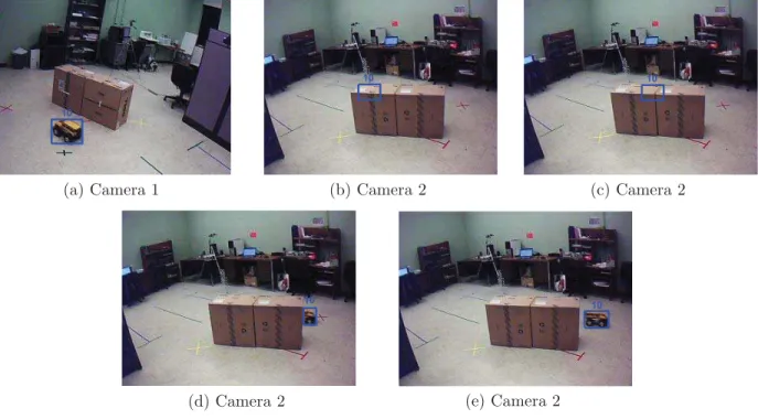
Figure 2.2 shows an example of resolving a merge. In Figure 2.2 (a), there are two objects in the view with labels 21 and 22, respectively. They are detected to be merging into one blob as shown in Figure 2.2 (b). In the merge state, both of the labels 21 and 22 are displayed on the blob. They split later and are matched to their correct trackers in Figure 2.2 (c). However, there may be some unfavorable cases that they are not matched to their correct trackers after they split. This may happen if their appearances are very similar.