Layer for Reactive Stream Processing
Networks on The SCC Many-core
Tiled Architecture
Nilesh Karavadara
A thesis submitted to the University of Hertfordshire
in partial fulfilment of the requirements of the degree of
Doctor of Philosophy (PhD)
April 2016
“Life is like riding a bicycle. To keep your balance you must keep moving.”
belief in me.
My sister Usha and brother-in-law Bharat, for always being there when I needed them. My wife Jaya and, daughters Aria and Jia for making me smile every day and provide
with unconditional love and great understanding, and also reminding me the reasons why I am following this dream. Also my nieces Ria, Esha and Neera for filling my life with lots of wonderful moments and also the much needed distraction from the work.
In computing the available computing power has continuously fallen short of the demanded computing performance. As a consequence, performance improvement has been the main focus of processor design. However, due to the phenomenon called
“Power Wall”it has become infeasible to build faster processors by just increasing the processor’s clock speed. One of the resulting trends in hardware design is to integrate several simple and power-efficient cores on the same chip. This design shift poses challenges of its own. In the past, with increasing clock frequency the programs became automatically faster as well without modifications. This is no longer true with many-core architectures. To achieve maximum performance the programs have to run concurrently on more than one core, which forces the general computing paradigm to become increasingly parallel to leverage maximum processing power.
In this thesis, we will focus on theReactiveStreamProgram(RSP). In stream processing, the system consists of computing nodes, which are connected via commu-nication streams. These streams simplify the concurrency management on modern many-core architectures due to their implicit synchronisation. RSP is a stream pro-cessing system that implements the reactive system. The RSPs work in tandem with their environment and the load imposed by the environment may vary over time. This provides a unique opportunity to increase performance per watt. In this thesis the research contribution focuses on the design of the execution layer to run RSPs on tiled many-core architectures, using the Intel’sSingle-chipCloudComputer (SCC) processor as a concrete experimentation platform. Further, we have developed a
DynamicVoltage and Frequency Scaling(DVFS) technique for RSP deployed on many-core architectures. In contrast to many other approaches, our DVFS technique does not require the capability of controlling the power settings of individual com-puting elements, thus making it applicable for modern many-core architectures, with which power can be changed only for power islands. The experimental results confirm that the proposed DVFS technique can effectively improve the energy efficiency, i.e. increase the performance per watt, for RSPs.
I always believed what Drake said: “Sometimes it’s the journey that teaches you a lot about your destination”. I could say that my journey through the PhD process has been difficult, enlightening, and rewarding, and it certainly could not have been reached at this stage without the support of a number of people.
Foremost, I would like to thank my principal supervisor and mentor Priv.-Doz. Dr. techn. Raimund Kirner. Without his excellent guidance, encouragement, and support, this thesis would not have been possible. I feel really fortunate to have worked with him and have learnt a lot of things from him, not just related to studies but also useful things for everyday life. Furthermore, my thanks go to my secondary supervisor Prof. Sven-Bodo Scholz. He caught my interest in compilers and runtime systems in the first place and introduced me to the Compiler Technology and Computer Architecture group (CTCA) group at the University of Hertfordshire. Furthermore, I would like to thank Prof. Alex Shafarenko who hosted me in the CTCA group and provided the well-equipped research environment.
I would like to thank all my colleagues in the CTCA group, for all their technical support as well as many parties and fun times together.
I would particularly thank Carl Joslin, Frank Penczek and Vu Thien Nga Nguyen for their support during the starting period of my PhD journey. I am indebted to Michael Zolda for mentoring me. His insightful comments on my research ideas had an important impact on this thesis. I also enjoyed the time we spent in long technical discussions. He always encouraged me and helped me to preserve my motivation during the hard times of debugging and benchmarking the beast (the SCC). Without his guidance and support, this thesis would not have been possible.
During my years at the Science and Technology Research Institute (STRI) I made many great friends, including Htoo (Phothar), Chaminda, Santanu, Simon, Maxim, Saverio, Vincent, Pavel and many more.
The most awaited time of the day for me was the lunchtime with Phothar, Chaminda and Santanu when we would debate anything and everything. I remember sometimes those conversions would stretch over a few days. It was fun and they provided a much needed distraction during stressful times. Thank you all for the good times
we shared together. The support staff at STRI deserve a special mention: Lorraine, Kathy, Michaella, and Avis. They cheerfully dealt with every piece of paperwork that I needed.
I also extend my thanks to the Intel Corporation and Intel Labs, for providing me with the opportunity to work on their research processor, called Single-Chip Cloud Computer (SCC). When they decided to shut down the data-centre that hosted the SCC, they agreed to send the system with the SCC to our University. This would not have been possible without hard-work from Raimund, who convinced them to send the SCC system to us so that I could complete my research.
I would also like to thank my friends Hiren Vadukar, Dr Jay Lakhani, Dr Prakash Vadukar, Vijay Vadukar, Chandresh Kishor, Hardash Bhutiya, Hiren Jungi, Faizal Hala, Jitesh Vithlani, Darshak Vithlani, Jagdish Gogra, Jignesh Joshi, Ketan Mehta, Naresh Kyada, Piyush Goswami, Rasendu Pandya, and Tejas Bapodra, who provided their support across continents.
Also, special thanks to Ben Saunders, Rahul Makwana, Snehal Virchand, and Kapil Gohil. I could not thank Rashid enough for helping me out numerous times, no matter what the time of day. I will never forget driving up to Newcastle upon Tyne simply to have a dinner and come back.
My special thanks to Dr Chris Wellings, Edmund Ward, and my superviser Priv.-Doz. Dr. techn. Raimund Kirner for proofreading this thesis.
Last, but not least, I owe my deepest gratitude to my grandparents, my uncles Masri and Bhoja, my aunties Shanti and Hansa, and my cousins Arun, Amar, Sheena, Selina, and Alysha for their support and motivation all along the way.
Abstract vii
Acknowledgements ix
List of Figures xv
List of Tables xvii
List of Code Listings xix
List of Algorithms xxi
Abbreviations xxiii
1 Introduction 1
1.1 Research Questions . . . 4
1.2 Contributions . . . 5
1.3 Publications . . . 6
1.4 Structure of the Thesis . . . 6
2 Background 9 2.1 Stream Programming . . . 9
2.1.1 Stream Programming Models . . . 10
2.1.2 Properties of a Stream Program . . . 11
2.1.3 Stream Programming Languages . . . 12
2.1.4 Reactive Stream Programs . . . 14
2.2 Execution Model of RSPs with S-Net as an Example . . . 16
2.2.1 S-Net Language . . . 16
2.2.2 S-Net Compiler . . . 22
2.2.3 S-Net Runtime Systems and Distribution Layers . . . 22
2.2.4.1 LPEL - A Stream Execution Layer with Efficient
Scheduling . . . 24
2.2.4.2 Distributed S-Net with LPEL . . . 26
2.2.5 S-Net Terminology at a Glance. . . 27
2.3 Power and Energy Optimisation . . . 28
2.3.1 Power Efficiency vs Energy Efficiency . . . 29
2.3.2 Dynamic Power Consumption . . . 30
2.4 Many-Core Network on Chip Platforms . . . 30
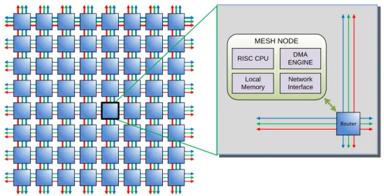
2.4.1 The Tilera TILE64 Processor. . . 31
2.4.2 Adapteva Epiphany-64 . . . 33
2.4.3 ClearSpeed CSX700 . . . 35
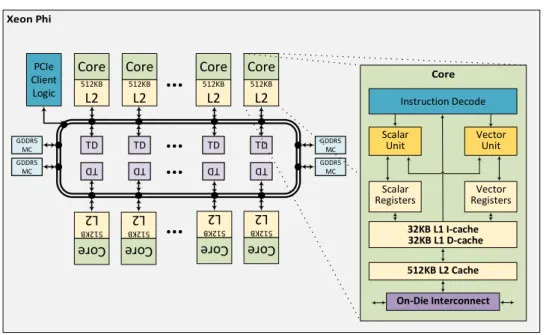
2.4.4 Intel Xeon Phi . . . 37
2.5 Single-chip Cloud Computer . . . 38
2.5.1 Top-level Architecture . . . 39
2.5.2 Tile-level Architecture . . . 40
2.5.3 Configuration Registers and FPGA Registers . . . 41
2.5.4 Memory Architecture. . . 42
2.5.4.1 Message Passing Buffer . . . 43
2.5.4.2 Cache Policy . . . 44
2.5.4.3 Lookup Table . . . 46
2.5.4.4 Address Translation . . . 47
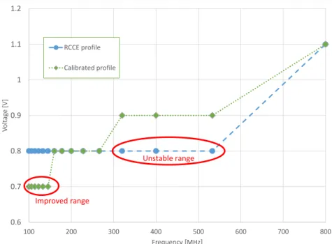
2.5.5 Voltage and Frequency Scaling . . . 48
2.6 Chapter Summary . . . 50
3 Design and Implementation of the Execution Layer 53 3.1 Shared Memory Motivation . . . 53
3.2 Shared Memory Initialisation . . . 55
3.2.1 LUT Remapping . . . 57
3.2.2 Memory Mapping . . . 60
3.3 HALLOC: A Hierarchical Memory Allocator . . . 65
3.3.1 HALLOC Design Criteria and Concepts . . . 66
3.3.2 Memory Allocation . . . 68
3.3.3 Memory De-allocation . . . 71
3.4 LPEL on the SCC . . . 74
3.4.1 Conductor/Worker Initialisation on the SCC . . . 74
3.4.2 Synchronization Primitives . . . 75
4.1 Resource Model and Resource Management System . . . 77
4.2 Influence of Load Balancing . . . 78
4.3 Resource Underload. . . 80
4.4 Resource Overload . . . 80
4.5 Load Ranges for RSP with Different Arrival Rate . . . 80
4.6 Load Ranges for RSP with Different Arrival Rate and DVFS . . . 82
4.7 Chapter Summary . . . 84
5 RA-LPEL: Resource-Aware Execution Layer 87 5.1 Recapitulation of Power Optimisation with the SCC . . . 87
5.2 Heuristics to Adjust Power Consumption . . . 88
5.2.1 Detecting Overload . . . 89
5.2.2 Detecting Underload . . . 90
5.2.3 DVFS Policy . . . 90
5.2.4 Frequency Adjustment . . . 91
5.3 Islands or Chip Level DVFS . . . 92
5.4 Chapter Summary . . . 93
6 Experimental Evaluation 95 6.1 Use Cases . . . 95
6.1.1 Fast Fourier Transform (FFT) . . . 96
6.1.2 Data Encryption Standard (DES). . . 97
6.1.3 Colour Histogram Calculation . . . 98
6.1.4 Image Filter . . . 100
6.1.5 Face Detection . . . 101
6.2 Experimental Set Up . . . 102
6.2.1 Data Collection and Post-Processing . . . 102
6.3 Performance Experiments. . . 103
6.3.1 Central Work Queue Bottleneck at the Conductor . . . 109
6.4 Power Optimisation Experiments . . . 110
6.4.1 Effectiveness of Power Saving . . . 111
6.4.2 Influence of Thresholds. . . 111
6.5 Chapter Summary . . . 123
7 Related Work 125 7.1 Distributed S-Net on the SCC. . . 125
7.2 Hierarchical Memory Management Mechanism . . . 127
7.4 Chapter Summary . . . 134
8 Conclusion and Outlook 135 8.1 Thesis Summary . . . 135
8.2 Conclusion . . . 137
8.2.1 Research Questions: a Retrospective . . . 139
8.3 Outlook . . . 141
2.1 Program Structure of the Image Filter Application . . . 15
2.2 S-Net Execution Model Overview[103] . . . 17
2.3 Serial Composition . . . 19
2.4 Parallel Composition . . . 20
2.5 Serial Replication . . . 20
2.6 Parallel Replication . . . 20
2.7 Feedback Loop . . . 21
2.8 LPEL with Centralised Scheduler . . . 25
2.9 TILE64 Architecture Diagram[3] . . . 31
2.10 Adapteva Epiphany-64 Architecture Diagram[59] . . . 33
2.11 ClearSpeed CSX700 Architecture Diagram[57] . . . 36
2.12 Xeon Phi Coprocessor Architecture Diagram . . . 37
2.13 Simplified Intel SCC Architecture Diagram[75] . . . 39
2.14 Memory Type and Cache Interaction[114] . . . 45
2.15 Address Translation[75] . . . 48
2.16 Frequency-Voltage Profile of the SCC . . . 50
3.1 Execution Model of S-Net for the SCC . . . 54
3.2 Default LUT Entries for Cores 0, 1 and 47 . . . 58
3.3 Private LUT Entries for Donor Cores 17, 18, 29 and 30 . . . 58
3.4 Remapped LUT Entries for Cores 0, 1 and 47 . . . 59
3.5 Shared Memory Layout . . . 67
3.6 A Chunk with Header . . . 69
4.1 Load Ranges for RSP with Different Arrival Rate in Terms of Through-put and Latency[103] . . . 81
4.2 Load Ranges for RSP with Different Arrival Rate and Effect of the DVFS . . . 83
6.2 A Schematic Representation of the DES as an S-Net Network. . . 97
6.3 A Schematic Representation of the Histogram Application as an S-Net Network . . . 99
6.4 A Schematic Representation of the Image Filter Application as an S-Net Network . . . 100
6.5 A Schematic Representation of the Face Detection Application as an S-Net Network . . . 101
6.6 Performance of FFT on Uncached-RA-LPEL, Cached-RA-LPEL and MPI-LPEL . . . 104
6.7 Scalability of FFT on Uncached-RA-LPEL . . . 105
6.8 Scalability of DES on Uncached-RA-LPEL . . . 105
6.9 Scalability of Histogram on Uncached-RA-LPEL . . . 106
6.10 Scalability of Image Filter on Uncached-RA-LPEL . . . 106
6.11 Scalability of Face Detection on Uncached-RA-LPEL . . . 107
6.12 Average Service Requests Received per Second by the Conductor . . 109
6.13 FFT with Thresholdsolth=0.20 andwwth=3.0 . . . 113
6.14 DES with Thresholdsolth=0.20 andwwth=3.0 . . . 113
6.15 Histogram with Thresholdsolth=0.20 andwwth =3.0 . . . 114
6.16 Image Filter with Thresholdsolth=0.20 andwwth=3.0 . . . 114
6.17 Face Detection with Thresholdsolth=0.20 andwwth =3.0 . . . 115
6.18 FFT with Different Choices of Thresholdsolthandwwth for DVFS . . 117
6.19 DES with Different Choices of Thresholdsolthandwwth for DVFS. . 118
6.20 Histogram with Different Choices of Thresholdsolthandwwthfor DVFS119 6.21 Image Filter with Different Choices of Thresholdsolth andwwth for DVFS . . . 120
6.22 Face Detection with Different Choices of Thresholds olth andwwth for DVFS . . . 121
2.1 Various Memory Access Latencies[77] . . . 44 2.2 LUT Entries for the SCC with 32 GiB of System Memory[75] . . . . 47 2.3 Voltage and Maximum Frequency Values[77] . . . 49 3.1 Example of LUT Mappings with Different Number of Entries in
Round-robin Manner . . . 61 5.1 Policy for Changing the Frequency . . . 91 6.1 Minimal and Maximal Task Execution Time for Benchmarks Running
on 40 Cores . . . 108 6.2 Total Wall-clock Time, Average Power Level, and Total Energy
Con-sumption of Each Benchmark Under Three Different Energy Policies, as Mean Over Five Runs . . . 112 6.3 Average Power Level, Wall-clock Time, and Total Energy
Consump-tion for Different Threshold Values ofolth andwwth Under the DVFS Policy, as Mean Over Three Runs . . . 116
2.1 S-Net Implementation of the Image Filter Application . . . 18
3.1 Partial Pseudocode of the SCC Platform Initialisation Function . . . . 62
3.2 Partial Pseudocode of a Shared Memory Initialisation Function . . . . 64
6.1 S-Net Implementation of the FFT Algorithm . . . 96
6.2 S-Net Implementation of the DES Algorithm . . . 97
6.3 S-Net Implementation of the Histogram Application . . . 99
6.4 S-Net Implementation of the Image Filter Application . . . 100
1 Algorithmscc_malloc_globalto AllocatemBytes from SHM-Arena . 69 2 Algorithmscc_mallocto AllocatenBytes from Free List of Chunks . 70 3 Algorithmscc_freeto De-allocate Memory Pointed by p . . . 72 4 Algorithmscc_free_garbageto De-allocated Memory from Garbage List 73
Abbreviation Elongated Page List
HALLOC HierarchicalAllocator 5, 7, 53, 66, 68, 74–
76, 125, 127, 128,
136–140
SAC SingleAssignmentC 18,27
ADC Analogue toDigitalConverter 92,102
AIR AtomicIncrementCounter 73
ALU ArithmeticLogicUnit 35
ANSI AmericanNationalStandardsInstitute 13,14,18,27,31
API ApplicationProgrammingInterface 5,127,128,134
AST AbstractSyntaxTree 22
BMC BoardManagementController 102
CCF ClockCrossingFIFO 40
CMOS ComplementaryMetal-OxideSemiconductor 29
CPU CentralProcessingUnit 2, 28, 29, 34, 129–
131
CRB ControlRegisterBuffer 40,41,46–48,55,60
CRI CommonRuntimeInterface 22,23,26
CTQ CentralTaskQueue 24,53,109
CUDA ComputeUnifiedDeviceArchitecture 13
DDR DoubleDataRate 31,35,42
DES DataEncryptionStandard 97,98,107,110,111,
122
Abbreviation Elongated Page List
DFS DynamicFrequencyScaling 110, 111, 115, 129,
137
DFT DiscreteFourierTransform 96
DIMM DualIn-lineMemoryModule 39
DMA DirectMemoryAccess 32,34
DPM DynamicPowerManagement 29,131,132
DRAM DynamicRandomAccessMemory 34,35,39,42
DSA DynamicStorageAllocation 65,66
DVFS DynamicVoltage andFrequencyScaling vii, 3–7, 9, 29, 30,
38, 39, 77, 79, 82, 84,85,87,92,93,95, 110, 111, 115, 122, 123, 125, 129, 131– 134, 136, 137, 139– 142
ED2P EnergyDelay-squaredProduct 28
EDP EnergyDelayProduct 28
EMA ExponentialMovingAverage 89,90
FFT FastFourierTransform 96, 103, 104, 107,
110,111,115,122
FID FrequencyIdentifier 130
FIFO FirstInFirstOut 10, 16, 23, 26, 75,
131
FPGA FieldProgrammableGateArray 34,39,42,102,127
FPU FloatingPointUnit 34,35
GCU GlobalClockingUnit 40
GDDR5 GraphicsDDRtype5 37
GPGPU GeneralPurposeGraphicsProcessingUnit 3
GPU GraphicsProcessingUnit 1,3
I/O Input/Output 22,31,34,35,50,88,
132,133
IA IntelArchitecture 40
IALU IntegerArithmeticLogicUnit 34
IM InputManager 26,27,127
IPN InterprocessorNetwork 37
ISA InstructionSetArchitecture 43
KPN KahnProcessNetwork 10,11,14
LMB LocalMemoryBuffer 40
LPEL Light-weightParallelExecutionLayer 23,24,26,27,53,55,
59,74–76,103,104,
137
LUT LookupTable 40,41,43,46,47,55–
57,59,60,65,74–76,
126,137
MAR MemoryAccessRate 132
MC MemoryController 31,37,39,40,42,46–
49,59,60,87
MCPC ManagementConsolePC 39,47,102
MESH MemoryEfficientSharing 128
MIC ManyIntegratedCore 37
MIT MassachusettsInstitute ofTechnology 13
MIU MeshInterfaceUnit 40,41,45–47
MMU MemoryManagementUnit 47
MPB MessagePassingBuffer 40, 42, 43, 46–48,
55,60,63,65,74–76,
126,127,137,139
MPBT MessagePassingBufferType 43–46
MPI MessagePassingInterface 23,26,103,104,126,
130–133
MPPA MassivelyParallelProcessorArray 2,110,139,142
MSR ModelSpecificRegister 130
Abbreviation Elongated Page List MVF MaximalVoltage andFrequency 111,115
NoC NetworkonChip 6, 7, 9, 30, 31, 35,
50,51,111,127,132, 133 ODI On-DieInterconnect 37 OM OutputManager 26,27,127 OS OperatingSystem 5,23,24,27,28,32– 34,38,43,55,56,72, 74,76,125,127–129, 132, 134, 136, 138, 139
PCIe PeripheralComponentInterfaceExpress 37,39
PCL PortableCoroutineLibrary 55
PE ProcessingElement 21,22,26,27,31,33,
35,131
PGAS PartitionedGlobalAddressSpace 129
PIO ProgrammedInput/Output 35
PMC PowerMeasurementController 102
POP-SHM PrivatelyOwnedPublicSharedMemory 128
POSIX PortableOperatingSystemInterface [for Unix] 23,71,76
QoS QualityofService 132
RA-LPEL Resource-Aware Light-weight Parallel
ExecutionLayer
5–7,87,93,95,103,
104, 109, 110, 123,
135–137,139–142
RC RuntimeComponent 16,23,27,28
RISC ReducedInstructionSetComputer 34,35
RSP ReactiveStreamProgram vii,3–5,7,9,15,16, 22, 50, 51, 55, 65, 68,77,80,81,84,85, 87,93,102,110,125, 127, 133–137, 139– 142 RTS RuntimeSystem 6, 9, 13, 16, 18, 22, 23,26,27,53,55,74, 125,132,142
SCC Single-chipCloudComputer vii, 4, 5, 7, 9, 23,
31,38–44,46–51,53, 55, 56, 60, 63, 66, 70,74–76,78,87,88, 92,93,95,102,103, 110, 115, 123, 125– 128, 132, 133, 136– 142
SDF SynchronousDataFlow 10,11,13,14
SDK SoftwareDevelopmentKit 34
SIF SystemInterface 39,46,49
SIMD SingleInstructionMultipleData 35
SISO SingleInputSingleOutput 18,19,23
SMC SoftwareManagedCache-coherence 128
SMP SymmetricMultiprocessing 33,38,139
SPMD SingleProgramMultipleData 130
SRAM StaticRandomAccessMemory 34,35,40,42
SSE Sum ofSquareErrors 90
SSH SecureShell 138
T&S Test-and-Set 41,70,76,139
TCP/IP TransmissionControlProtocol/InternetProtocol 47
TD TagDirectory 38
TDMA Time-DivisionMultipleAccess 132
TG TrafficGenerator 40
Abbreviation Elongated Page List
UID Unique dataIdentifier 27
VF Voltage andFrequency 84,85
VFI Voltage-FrequencyIsland 78,79
VHDL VHSICHardwareDescriptionLanguage 13
VID VoltageIdentifier 130
VLIW VeryLongInstructionWord 32
VPU VectorProcessingUnit 37
VRC VoltageRegulatorController 39,47,49,88
Introduction
Gordon Moore’s conjecture was: “The number of transistors placed on an integrated circuit doubles approximately every two years”[101]. This became known as “Moore’s Law”; it proved accurate for several decades and fuelled the growth of the computer industry by providing faster processors. And yet the demand for computational power has always exceeded the supply [98]. As an example, the recently released Oculas Rift virtual-reality headset requires approximately 3.5x the rendering power needed to render a game at the resolution of 1080p and frame rate of 60 frames per second. This is due to the fact that the headset requires even higher resolution, higher refresh rate, and 3D processing capabilities. This means that almost all of theGraphicsProcessing
Units (GPUs) which were capable of rendering a game a few months ago are not powerful enough for the Oculas Rift[20].
The trend of shrinking transistors to increase clock speed and build a faster pro-cessor worked well, but it meant that with a faster clock speed, more power was needed per unit area. Although one might think that a smaller feature size means less power consumption, the increased clock frequency and higher number of gates have over-compensated this reduction. With the increase in required power per die area came the problem known as“Power Wall”, i.e. processors generated so much heat that dissipating this heat efficiently became a problem[8, 35], so much so that it has become infeasible to build faster processors by increasing the processor’s clock speed[119]. Furthermore, in the wake of green computing, the power available to a processor is not increasing in comparison to the amount of data that is to be processed. This has moved the industry’s focus from raw performance toperformance per watt. Another contributing factor is the rise of the mobile devices, for which a longer battery life is usually desired.
Physical barriers in making processors faster by increasing the clock frequency and the need for energy-efficient computing have paved the way for many-core computing to become mainstream.
One approach to the problem of reducing power consumption and increasing processing power is to replace one complex and power-hungry core with several simpler but more power-efficient ones[22, 23, 119].
As the heat and interference caused by increased clock speeds and shrinking transistor size are starting to limit processor designs[22, 23], processors such as the Intel Xeon Phi[30], ARM (Cortex A7 & A15)[45], Tilera TILE64[13], and Kalray MPPA2-256[66] reflect a trend towards tiled many-core architectures. This trend of increasing the number of cores integrated in a single die is expected to increase steadily in the foreseeable future[22]. In addition to physical barriers, this move to many-core chips is driven by a need to get moreperformance per watt.
This approach comes at a price. In the past, as the clock frequency increased, programs running on these faster processors became faster without any modification. However, this is not true anymore with the many-core architectures. To achieve maximum performance, the programs have to run concurrently on more than one core[119]. While parallel programming has a long tradition in the field of scientific computing, to leverage maximum processing power made available by many cores on the chip, the general computing paradigm has to become increasingly parallel.
This shift to parallel programming puts a burden on programmers, as the identific-ation and exposition of the concurrency becomes the responsibility of the programmer. Furthermore, programmers have to worry about the decomposition and mapping of a computation to the cores to achieve optimal utilisation.
Another issue on many-core architecture is data consistency. Most current multi-coreCentralProcessingUnits (CPUs) are organised around cache-coherent shared address space, in which memory consistency is maintained by the hardware on behalf of the programmer. However, in the Shared Memory Multiprocessor systems the memory consistency is usually handled by the hardware, which incurs some protocol overhead. This protocol overhead can vary, based on the used cache-coherency mechanisms [92, 122]. As we add more cores to the chip, the protocol overhead becomes a bottleneck and all gain from adding more cores is lost. The problem comes from the fact that any technical implementation that exists today is based on the idea of caches. In order to have a consistent view of memory across all cores it is necessary to invalidate cache lines which are modified by other cores. The technologies that exist today are not scalable for thousands of cores[92, 122]. As a solution, one approach is to build a processor with no support of hardware-based cache-coherency; this seems to scale well with hundreds or even thousands of cores.
we have architectures which can scale to hundreds or even thousands of cores, but we are facing increasing difficulties in writing programs that run efficiently on them. Moreover, in order to achieve optimal performance on such an architecture the pro-grammer needs knowledge of the underlying hardware. As an example, General
PurposeGraphicsProcessingUnit(GPGPU) provides many computation cores, but in order to get maximum performance the programmer has to know how and when to move the data correctly from the main memory of the computer to the various memories of the GPU hardware. Furthermore, the programmer has to take care of load balancing, i.e. all cores taking part in a computation should have a nearly equivalent workload. Otherwise, some cores will remain idle while others are processing data, increasing the wall clock time that the program takes to complete [119], wasting resources and increasing energy consumption as a result.
Effectively programming many-core architectures is currently the domain of ex-perts. However, one programming paradigm that addresses the complexity involved in achieving maximum processing power from such architecture isstream processing.
Under the stream processing paradigm, programs are constructed by computational nodes connected by unidirectional communication channels. Each compute node can be executed as soon as data is available on its input streams. Streams are communica-tion channels to transfer sequences of data among computacommunica-tion nodes. These streams simplify the concurrency-management on modern many-core architectures due to their implicit synchronisation.
In this thesis, we will focus on stream programs that continually respond to external inputs and process virtually infinite sequences of data. We refer to such stream programs asReactive Stream Programs(RSPs), to differentiate them from general stream programs, where the programs respond to rather small and finite input data. An example of RSP is real-time video encoding, where the encoder needs to process incoming video frames as they arrive.
The RSPs work in tandem with their environment, where the load imposed by the environment may vary over time. This provides a unique opportunity to increase
performance per watt. Optimisation of power consumption is important, especially if RSPs are used in resource-constrained environments.1 For example, if the system load imposed by the environment varies over time, the use of dynamic power management techniques like Dynamic Voltage and Frequency Scaling (DVFS) can be used to effectively reduce the power consumption of such systems. Expanding the example of real-time video encoding, the computational resources needed vary greatly depending on the captured scenery: detailed sceneries with fast, complex movements are much
more computationally intensive than still scenes with few details. The challenge in dynamic power management for RSPs is to save power at the right time, without violating the system’s throughput and latency constraints. This is a hard problem, because the future resource requirements can be unpredictable for many important applications.
In this thesis, we present an execution layer that provides light-weight DVFS support for RSPs. We target the Single-chip Cloud Computer (SCC) many-core processor as a concrete example to evaluate our approach. The SCC is a research processor from Intel. It provides 48 cores and a flexible infrastructure for DVFS. Compared to other commercially available tiled many-core architectures, it supports more independent on-die voltage and frequency domains. Moreover, since the SCC is based on IA-32 cores, a legacy benchmark code can be easily ported.
1.1
Research Questions
Although RSPs are in general well suited for many-core architectures, they work in tandem with their environment, in which the load imposed by the environment may vary over time. Keeping this in mind, this thesis is motivated by the following research question:
Is it possible to improve the adaptive resource utilisation and improve the energy efficiency of RSPs on many-core platforms by exploiting knowledge about the states of the system?
This question is split into the following sub-questions:
1. What is an efficient way to port an existing RSP execution layer to the SCC? 2. What are meaningful performance-indicators to identify the workload situation
of an RSP on a many-core processor?
3. Is it possible to have these performance-indicators to be independent of any specific hardware feature of that many-core processor?
4. What are the adequate strategies to optimise the performance per watt of RSPs on many-core platforms?
5. Is it possible to design DVFS strategies that are light-weight and simple, but still adequate to provide substantial reduction in energy consumption of RSPs?
This thesis will make the following contributions, aiming to answer the proposed research question:
1. The development of the first RSP execution layer for the many-core processor SCC that retains the shared memory programming model.2
2. We present theHierarchicalAllocator (HALLOC), a novel hierarchical memory creation and management scheme for the SCC.
3. We discuss and identify performance metrics to identify the workload situation, which can be used to develop DVFS strategies for RSPs on many-core processors. These metrics do not depend on any specific hardware features of the many-core processor.
4. We presentResource-AwareLight-weightParallelExecutionLayer(RA-LPEL), a resource-aware execution layer for RSPs on many-core architectures.
5. We evaluate the effectiveness of our DVFS method for RSPs in terms of im-provement of energy efficiency.
Contributions 1 and 2 answer the first research sub-question, i.e. finding an effi-cient way to port an existing RSP execution layer to the SCC. We have developed the so-called HALLOCmemory manager, which provides a way to create the illusion of a shared memory on the SCC. Furthermore, it also hides the cumbersome details of alloc-ation and deallocalloc-ation from the end-user, offering a simpleApplicationProgramming
Interface(API) to work with. The main distinction of HALLOC—that separates it from multi-threaded memory allocators—is that it is not simply a memory manager; instead it is a complete mechanism that creates the shared memory—the instance of an
OperatingSystem(OS) running on the SCC is not aware of the existence of this shared memory—at the application level and provides functionality to manage this memory. Contribution three addresses both the second and third research sub-questions, since they are intertwined. We consider the throughput and available resources as major indicators of performance of the RSPs. Furthermore, the available resources and throughput can be considered to be independent of hardware architecture.
2There has been before a successful attempt to port a stream-processing environment to the
SCC[135]. This approach was made for a concrete coordination language, called S-Net. Our
ex-ecution layer is not bound to a particular coordination language, and did not require refactoring the code for the sake of avoiding shared memory communication.
Contributions 4 and 5 answer the fourth sub-question by introducing the RA-LPEL and by experimentally evaluating the different DVFS policies on the actual hardware. We report a substantial reduction in energy consumption.
1.3
Publications
Most of the work in this thesis has been published in the following papers:
• Nilesh Karavadara, Simon Folie, Michael Zolda, Nga Nguyen, Raimund Kirner,
“"A Power-Aware Framework for Executing Streaming Programs on Networks-on-Chip”, In Proc. International Workshop on Performance, Power and Pre-dictability of Many-Core Embedded Systems (3PMCES), Electronic Chips and Systems Design Initiative (ECSI), Dresden, Germany, March 2014. doi: 10.13140/RG.2.1.1684.4400. Available at http://dx.doi.org/10.13140/RG.2.1. 1684.4400
• Nilesh Karavadara, Michael Zolda, Vu Thien Nga Nguyen, and Raimund Kirner,
“A Hierarchical Memory Management for a Load-Balancing Stream Processing Middleware on Tiled Architectures”, In 18th Workshop on Programming Lan-guages and Foundations of Programming (KPS’15), Technische Universität Wien, Pörtschach, Austria, October 2015. Available at http://www.complang. tuwien.ac.at/kps2015/proceedings/KPS_2015_submission_50.pdf
• Nilesh Karavadara, Michael Zolda, Vu Thien Nga Nguyen, Jens Knoop, and Raimund Kirner,“Dynamic Power Management for Reactive Stream Processing on the SCC Tiled Architecture”, EURASIP Journal on Embedded Systems, 2016(1):1–17, June 2016. ISSN 1687-3963. doi: 10.1186/s13639-016-0035-9. Available at http://dx.doi.org/10.1186/s13639-016-0035-9
1.4
Structure of the Thesis
The remainder of this thesis is organised as follows:
Chapter2provides the necessary background in the context of this thesis. This includes stream programming with details on models, languages, and properties of stream programs. Furthermore, we describe the execution model for S-Net language. This includes the description of the S-Net language, followed by the detailed descrip-tion of the compiler, theRuntime Systems(RTSs), and the execution layers for the S-Net. This chapter also covers some aspects of power and the energy optimisation for computers in general. An overview of theNetworkonChip(NoC) architectures
description of the Intel’s experimental research processor, the SCC. S-Net serves as a programming language for the RSPs and the SCC is used as a research vehicle for the experimental evaluation of our approach in this work.
Chapter3describes HALLOC, a novel hierarchical shared memory creation and allocation mechanism that forms part of the execution layer. It includes design criteria and a detailed implementation explanation of HALLOC. In addition, we will describe the execution layer initialisation procedure on the SCC hardware.
Chapter4covers definitions of workload and resource usage situations in general. In addition, it also provides a formal definition of load ranges for RSPs with different arrival rate, and then extends them by taking into account the impact of DVFS.
Chapter5discusses RA-LPEL, an execution layer with resource awareness for RSPs. This chapter covers the heuristics used in our experimental evaluation to adjust power consumption. Furthermore, we also describe various DVFS policies. In addition, we introduce guidelines which governs when to employ DVFS based on system state.
Chapter6starts by introducing a set of use cases of RSPs. These use cases are used as experimental benchmarks to evaluate efrficiency of our DVFS policies its impact on RSPs. Furthermore, experimental results are reported and analysed, with a focus on performance and energy optimisation.
Chapter7discusses the related work of this thesis, focusing on three main areas: another approach that targets the SCC with S-Net, memory-management, and energy optimisation. The related work in memory-management area covers approaches that focus on providing the shared memory-management functionality for NoC, while the related work for power optimisation covers approaches that use DVFS to reduce energy consumption.
Background
This chapter provides the necessary background for the rest of the thesis. In § 2.1
the programming paradigm on which we are focusing in this work is discussed. Introduction to the stream programming model is covered in § 2.1.1and in § 2.1.2we study the properties of the stream programs. An overview of different stream languages is provided in § 2.1.3, followed by an account ofReactiveStreamPrograms(RSPs) in § 2.1.4. Detailed description of the execution model of RSP with a concrete example of S-Net language is provided in § 2.2. For S-Net we provide an in-depth overview of the language in § 2.2.1, while the compiler, theRuntimeSystems(RTSs), and execution layers are covered in § 2.2.2, § 2.2.3and § 2.2.4respectively. A brief study of the power- and energy-optimisation is presented in § 2.3. We review some of the examples of the multi-core/many-core NetworkonChip(NoC) architectures in § 2.4. Finally, § 2.5 describes Intel’s Single-chipCloud Computer (SCC), an experimental processor with fine-grainedDynamicVoltage andFrequencyScaling
(DVFS) capabilities. In the context of this thesis we use the S-Net and the SCC as a research vehicle to conduct experiments.
2.1
Stream Programming
The philosophy behind stream/data-flow programming provides a drastically different way of looking at the computation from the von Neumann architecture with control-flow. In control-flow, the focus is on how control moves through the program and the order of the computation. In data-flow, the focus is on how data moves through the program and the availability of the data. With data-flow style scheduling becomes the responsibility of the system, and not of the programmer.
In data-flow programming a program is modelled as a directed graph of the oper-ator nodesrepresenting computations, connected byarcsrepresenting data path. In
contrast to control-flow paradigm, the activation/execution/firing of the operator node is dependent on the availability of the data on its input arcs. For readers interested in broadening their knowledge of the field of the data-flow programming, we list some surveys as invaluable resources[2, 63, 123, 139].
Similar to the data-flow programming paradigm, a program in stream programming is described by a directed graph in which the operator nodes denote operations and the arcs connecting them denote data dependencies between operations. For convenience, from now on we will refer to operator nodes simply asnodes. In the stream program-ming, the data arcs are represented asstreams. Now what do we mean bystreams? According to Lee and Parks there exist different definitions of the term stream in the literature[88]. One definition, for example, from Landin [84] and Burge [25], describes streams with recursion and lazy semantics. In this definition a stream is composed of two parts: first is the value of the head of the stream and the second is the procedure, which when evaluated produces the rest of the stream. According to another definition by Franco et al.[39]and by Dennis[34], streams are regarded as channels, or an infinite—or finite with unknown quantity—sequence of elements. In the context of this thesis, we use second definition, with which streams are regarded as channels.
2.1.1
Stream Programming Models
With the introduction of theKahn ProcessNetwork(KPN), Kahn’s main intention was to model concurrent systems, but the model has proved to be a convenient way to model signal processing systems as well[64, 65]. In KPN, the operator node is called acoroutineor process, while stream is identified aschannel. The processes of a KPN are deterministic and can be modelled as a sequential program, i.e. for the same input they always produce exactly the same output. The channel is an unboundedFirstInFirstOut(FIFO) queue. Since the channels are unbounded and processes are deterministic, the resulting KPN does not depend on the computation or communication delays and exhibits deterministic behaviour. Processes read/write atomic data elements calledtokensfrom/to channels. Since channels are unbounded, write operation is non-blocking, i.e. a process can write a token to the output channel at any time. In contrast, a reading operation is blocking, i.e. a process becomes blocked when reading from an empty input channel.
Since KPN channels are unbounded, a buffer overflow or even deadlock is possible. It is difficult to schedule a KPN because of the need to balance relative process rates. In 1987, Lee and Messerschmitt proposedSynchronousDataFlow(SDF), a restricted
a fixed number of tokens from each of its input/output channels. For an SDF graph, the rate at which a node consumes/produces tokens is known a priori. This makes the number of tokens produced/consumed independent of the input data. In order to avoid deadlock, each channel in SDF has an associated property calleddelay, which corresponds to a sample offset between the input and the output. A channel with some delayd means that the firstdnumber of tokens in that stream is not produced by a node, but is part of the initial state of the program. With the introduction of delay and knowledge of the token rate, SDF does not require unbounded channels as KPNs and it is guaranteed to have a static schedule.
2.1.2
Properties of a Stream Program
According to observations[103, 123]stream programs can be classified by properties of their nodes and streams, such as:
Stream Communication Type Streams can be eitheruni-directionalorbi-directional. In the case of the former, data travels in only one direction, while in the case of the latter data can travel in either direction. For example, let’s look at the two nodesAand Bconnected by streamS. In the case, whenSis uni-directional only one node can write to the stream while another node can only read from it. If streamSis bi-directional, both nodesAandBcan readandwrite from/to the same stream.
Node Computation Type Computation performed by a node can befunctional or
non-functional. A functional nodeF with the same inputI always produces the same output O; there is no state that can change this. A non-functional node
NF with the same inputI, may produce a different output, depending on other factors, e.g. the internal state of the node.
Node Computation Behaviour The behaviour of a node can beconstantorvariable
through the execution. For example, does the processing time for messages stay constant or does it change based on the input value of the message? Another example ismultiplicity2, which stays constant regardless of change in the input message or the node’s internal state in case of constant behaviour, whereas it would change if the node behaviour was variable.
1Hereafter, we will use the terminvoketo describe the action when a node performs its computation once. This action is also identified asexecution,firingoractivation.
2Multiplicity of a node is the ratio of the number of input messages to the number of output messages per node invocation. A node with multiplicity ofn-to-m, consumesnmessages from its input stream
Inter-node communication The communication that takes place over the stream between two nodes can besynchronousorasynchronous. If the communication is synchronous then there has to be a mechanism in place that would support synchronisation between the transmission and reception of the messages, i.e. a global clock. In case of asynchronous communication, there is no synchronisa-tion taking place between transmission and recepsynchronisa-tion, and as such a nosynchronisa-tion of time does not exist for communication purposes between nodes. In this case, reading and writing of the messages are proceeded independently.
Program Structure The structure of the program can bestaticor dynamic. For a program with property of static structure, the graph of the program in terms of ar-rangement and the number of nodes and the relationship between them by means of stream connection would not change. For a program with dynamic structure, the number of streams, the number of nodes, and the connection between them can change dynamically during the execution lifetime of a program.
2.1.3
Stream Programming Languages
As noted in [123]a number of programming languages have integrated the concept of streams. An exhaustive listing of the features of all the streaming languages can be very long. Bearing that in mind, we will give a brief overview of some of the notable languages here.
Each language introduces its own terminology to describe components of the language, some of the examples are:
The graph representing the application contains the vertices representing compu-tation and edges representing connection between them, also denoted as the
networkor anexecution plan
Vertices representing computation are also denoted as operator node, operator,
node,function,kernel,filter,component, orbox
Edges representing connection are also referred to aschannel,data path,stream, or
data arc
The action performed by a node is denoted by termsinvocation,execution,firing
oractivation
A single unit of data travelling on a stream can be identified asenvelope,message, orrecord
mented and compiled natively in the underlying systems, e.g. in C++. The streams are uni-directional, while the program structure is dynamic. The data is processed byoperators. The operators are made up of two parts: The first part contains strictly serial computation calledsub-operators, i.e. it should not be possible to decompose it any further. The second part specifies how all the sub-operators of an operator are connected. Apart from user-specified sub-operators, there are two implicit special sub-operators that define the input and the output for the operator. Each operator may have multiple inputs or outputs, which in turn allow operations like gather and scatter. The technical documentation presents a detailed description of the language syntax[12].
The application development environment calledAuto-Pipe[27]is geared towards simplifying the development of complex streaming applications for hybrid architec-tures. In order to achieve its goal, Auto-Pipe uses a coordination language calledX[40]
to connect kernels written in traditional languages in a data-streaming style, i.e. X can express the nodes and edges of a task-processing graph, as well as the configuration, platform definition, and device bindings. X allows representation of a program in terms of coordination and communication of kernels written in a different computation language. Since Auto-Pipe is targeting hybrid architecture, each kernel may have several platform-specific implementations, e.g.AmericanNationalStandardsInstitute
(ANSI) C, Compute UnifiedDevice Architecture(CUDA), and VHSIC Hardware
DescriptionLanguage(VHDL). All platform-specific implementations of a kernel are required to provide the same interface and streaming data semantics, e.g. input/output ports and data types. This in turn guarantees the correctness of a program, regardless of where each kernel is mapped. The runtime of X is responsible for making sure that the data arrives at the correct kernel, even if it is executed on a different platform. In addition to language X, the Auto-Pipe environment hasX-Com, a compiler that takes in the application’s specification of computation, resources, and a topology of these resources to generate a set of source files that can be compiled for each device in the system. TheX-Dep, an application deployment tool, is used to deploy the application on the target hardware.
StreamIt [127] from Massachusetts Institute of Technology (MIT) is believed to be the most popular streaming language based on the ideas of the SDF in the research community. StreamIt is accompanied by an optimising compiler and a RTS. Since StreamIt employs the SDF model, it requires the kernel to have static input and output rates. That is, the number of items consumed on the input stream and produced on the output stream must be constant, from one invocation to the next. Every StreamIt program is a hierarchical composition of three basic stream structures, called
Pipeline,SplitJoin, andFeedbackLoop. Although StreamIt is based on SDF, which requires synchronous communication between kernels, it also has a distinct feature calledteleport messagingthe ability to send control messages to other kernels as an asynchronous method call. These control messages are used to change the behaviour of the receiving kernel. In addition, as these control messages do not use the same infrastructure as data items, they can be communicated to the kernels independently of the data-flow graph of an application. To support node synchronisation, StreamIt introduces the conception ofinformation flow, in which messages can carry timing information when transferred over streams[128]. This is required as all the kernels in StreamIt execute independently, without any notion of global time. Since StreamIt is based on the SDF model, it only supports a static schedule. This in turn allows the compiler to perform enough analysis and optimisation to produce an efficient implementation.
S-Net is a declarative coordination language that aims to support the transition from sequential code to parallel code, where the concurrency handling is completely managed by S-Net[49]. The kernels are implemented in an independent computational language, e.g. ANSI C. The streams in S-Net are uni-directional. In contrast to StreamIt, the program structure in S-Net can be changed dynamically at runtime and S-Net provides asynchronous communication over streams. Furthermore, there is no restriction on the rate of consumption/production of messages on the streams. Compared to StreamIt, S-Net is more general and closer to KPNs. We will cover S-Net with a more detailed description in Section2.2.
2.1.4
Reactive Stream Programs
Harel and Pnueli[56]separated the computing systems into two classes: transforma-tional systemsandreactive systems. In transformational systems, a computer program is considered like a black box that accepts inputs, produces outputs by performing transformations on the inputs, and terminates. Transformational systems can be com-pletely described as relations between their inputs and outputs. In contrast, only the relation between inputs and outputscannotdescribe reactive systems completely. Re-active systems continuously respond to external inputs, i.e. a reRe-active system maintains an ongoing relationship with its environment by continuously interacting with it.
According to Berry[18]reactive systems can be broken down into two categories based on their relationship with its environment: reactive systems and interactive systems. The systems that continuously respond to external stimuli produced by their environment at the same speed at which the environment produces it are reactive systems, i.e. the environment decides when to produce the stimuli and the system
...
Splitter Filter0 Filtern Merger M0 M∞...
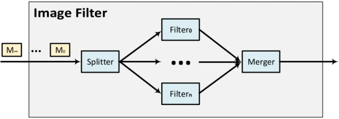
Figure 2.1 Program Structure of the Image Filter Application
responds to it. In contrast, interactive systems respond to external stimuli produced by their environment at their own speed.
The distinction between reactive and interactive systems is based on how they respond to stimuli from their environment, i.e. it is based on a program’s semantics, although there is no structural difference between a reactive and interactive system. Taking this into account, we use the same definition of a reactive system as in Harel and Pnueli[56], which covers both interactive and reactive systems and takes no account of the way they respond to their environment.
We use the term Reactive Stream Program (RSP) as it is by Nguyen [103]
to describe programs that fit into the category of a reactive system based on the definition above and designed as a stream program, i.e. RSPs arestream programs
that continuouslyreactto potentially never-ending stimuli from their environment, in contrast to a stream program with a rather small and finite input.
We will use image filter application as a running example of an RSP. Figure2.1
shows the structure of an image filter application. The application includes a node
Splitterthat reads messages (possibly infinite) containing images from the environment and splits them into messages containing sub-images. The messages with sub-images are sent to different branches whereFilternodes perform the actual filtering operation. Messages containing the filtered sub-images are then sent to theMergernode, which combines them into complete images and sends them out to the environment.
As we know in RSPs, data arrives from the environment as a virtually infinite sequence of messages. Nodes that receive messages from the environment are called
entry nodes and the input messages of these entry nodes are called external input messages. In our example, node Splitter is an entry node. In similarity to entry nodes, nodes sending messages to the environment areexit nodes. The messages produced by exit nodes are calledexternal output messages. The node Merger is an exit node, as can be seen from Figure2.1. The nodes that are between entry and exit nodes are calledintermediate nodesand, as such, all the messages inside the RSP are referred to
asintermediate messages, i.e. the messages that are not external input/output messages. In our exemplary image filter application, nodesFilter0toFiltern are intermediate
nodes.
Conceptually, the execution model of an RSP includes three layers: a compiler, an RTS and an execution layer. The compiler parses the source code of an RSP and generates the object code.
The RTS enforces the RSP’s semantics and uses the object code to allocate runtime objects. In terms of enforcing semantics, the RTS makes sure that each Runtime
Component(RC) reads from and writes to appropriate streams. The runtime allocation of the objects includes, but is not limited to, the FIFO buffers that represent streams and RC that represents an instance of a node or an operator.
The execution layer below the RTS, transforms RCs into executable objects called
tasksand provides an implementation of FIFO buffers to transfer messages between these tasks. The execution layer also provides a scheduler to distribute tasks to physical resources. In simple terms, a task is an iterating process that reads messages from its input streams, performs the associated node’s computations, and writes output messages to its output streams. Each iteration of a task is calledRC invocation. The termmultiplicitydefines the ratio of the number of input messages to the number of output messages per RC invocation. A task with multiplicity ofn-to-m, consumesn
messages from its input stream and producesmmessages in its output stream on each invocation.
2.2
Execution Model of RSPs with S-Net as an Example
As we already know, conceptually the execution model of an RSP includes three layers: a compiler, an RTS, and an execution layer. We use S-Net as a reference language and describe its compiler, RTS, and execution layer. The execution model of S-Net is illustrated in Figure2.2.
2.2.1
S-Net Language
S-Net[49]is a declarative coordination language. The main design principle of S-Net is to separate computations from concurrency management aspects. S-Net is a pure coordination language, as it does not provide the features to express computations but offers a notation for describing data dependencies in computation. In S-Net the computational logic is encapsulated inside the individual stateless computation components calledboxes. S-Net relies on auxiliary language to implement these boxes. In principle, any conventional programming language can be used to implement boxes.
CRI Deployer S-Net Reactive Stream
Program
S-Net Runtime Components
Task Component
Stream Component Common Runtime Interface
(CRI) Parser Context Checker Type Inference Optimiser Code Generator S-N e t R u n ti m e S ys te m Stream Manager Task Manager Box Language Interface Types & Patterns
I/O Distribution Threading
Conductor Worker worker
Core Core Core
LP E L Ex e cu ti o n L ay er H ar d w a re Centralised Schedular
net imageFilter ({image}→{filteredImage})
{
box Splitter((image) → (subImage, <branch>));
box Filter((subImage) → (subImage));
box Merger((subImage, <branch>) → (filteredImage));
} connect
Splitter .. Filter!<branch> .. Merger;
Listing 2.1 S-Net Implementation of the Image Filter Application
Currently, interfaces for a subset of ANSI C andSingleAssignmentC (SAC)[48]
are provided to be used as a box language. The boxes are connected by streams that facilitate communication between them.
The termnetworkis used to describe an application in S-Net with multiple boxes connected via streams. Each box in S-Net is aSingleInputSingle Output (SISO) component, i.e. they have a single input stream and a single output stream. These two streams connect a box to the rest of the network. The SISO components are either boxes or previously constructed networks. Large and complex networks can be constructed by combining these SISO components together. Any network, irrespective of its size and complexity, again is a SISO component.
Listing2.1shows the S-Net code of our running example of image filter application. In the S-Net, data in the form of themessagetravel through the streams. Each message is comprises a set of label-value pairs. There are two types of labels calledfieldsand
tags. Fields are completely opaque to the S-Net RTS and it gets manipulated only inside boxes, as they are associated with values from the box language domain. In contrast to fields, tags are integer numbers and accessible by both the S-Net RTS and the user-defined boxes. To differentiate the tag and the field, the tags are enclosed within angular brackets. In our running example of an image filter, <branch> is a tag whileimage,subImageand f ilteredImageare the fields.
The behaviour of the network and box in S-Net is declared by atype signature: a mapping from a single input type to one/multiple output type. In our example, node Splitter accepts messages with an image as an input and produces messages that contain thesubImageas a field and <branch> as a tag. Let’s look at a more complex example;
box foo ((a, <b>) → (c) | (c, d, <e>) );
The boxfooaccepts messages with field aand tag <b> and produces messages with either fieldcor with fieldsc,d and tag <e>.
foo bar
Figure 2.3 Serial Composition
To loosen the restriction of a single input type, S-Net supports an inheritance mechanism, calledflow inheritance. This allows a box to accept all sub-types of the box’s declared input type. Excess fields and tags of a message are bypassed through the box. That means that when a message arrives to a box, only entries with listed labels in the input type are taken by the box to generate output messages. These additional fields and tags are then added to each message emitted by the box in response to the input message if the output message does not contain the field and tags of the same name already. This means boxfooreceives any input records that have at least fielda
and tag <b>, but also records with further fields and tags. In our running example, the node Splitter produces messages with type(subImage,<branch>), whereas the next node Filter accepts messages with the type(subImage). In this case, tag <branch> is bypassed and added to the output messages that are sent to node Merger.
In addition to the boxes implemented in the box language, there are two built-in types of boxes in the S-Net, thefilter boxand thesynchrocell. The filter boxes support simple operations on the messages including adding or removing fields, splitting messages, and simple computations on tags. Since boxes/networks in S-Net are SISO, if a box/network requires data from several messages as input, these messages have to be merged first. S-Net provides synchrocell to do just that. A synchrocell is parameterised over the type of message that it is supposed to merge. As soon as it receives messages of all matching types, it releases a single combination of these messages. After producing the merged message, the synchrocells serve as an identity function, forwarding all incoming records.
In order to construct a network composed of boxes that represents a stream program, S-Net provides five network combinators.
Serial composition (denoted as..) and parallel composition (denoted as|) allow the construction of pipelines and branches respectively. Both combinators are static, in the sense that only one instance for each of their operands is created. As can be seen in Figure2.3, serial composition connects two components serially. For example, in f oo..bar serial composition connects the output of operand f oo to the input of operandbar. Parallel composition of f oo|barconnects f ooandbarin parallel. This can be seen in Figure 2.4. The message is routed to the operand network that best matches its type[49]by parallel compositor.
<Parallel Compositor>
foo
bar
<Collector>
Figure 2.4 Parallel Composition
<Serial Replicator> foo
<Collector>
<Serial Replicator> foo
Figure 2.5 Serial Replication
<Parallel Replicator>
foo
foo
<Collector>
foo <Feedback>
Figure 2.7 Feedback Loop
The next two combinators are dynamic, in the sense that they create replicas of their operands on demand. Serial replication (denoted as⋆) and parallel replication (denoted as !) allows construction of pipelines and branches of dynamic lengths respectively. The serial replicator in f oo⋆stopwill replicate the operand network f oo
and join then serially until the exit patternstopis met. Serial replicator is illustrated in Figure 2.5. Parallel replicator in f oo!<T> as depicted in Figure 2.6 will create instances of its operand f oofor every unique tag value <T> and combine them in parallel. Each message arriving to parallel replication is processed by only one of these instances. The tag value <T> will determine which instance will process the message and then message is routed accordingly.
The feedback combinator (denoted as\) is similar to a serial replication combinator as it takes one operand, but instead of an exit pattern it takes a continue pattern. If the message on the output stream matches the continue pattern, it is sent back as an input message to that operand. Figure2.7shows the feedback combinator for f oo\continue, where a feedback loop around the operand f oois created. All the messages matching the continue patterncontinuewill be sent back to f ooas input messages.
Only serial composition preserves message order, while others do not due to the fact that messages travel through different branches. In order to allow preservation of the message order, S-Net provides deterministic variants of these combinators. They are denoted as||for parallel composition,⋆⋆for serial replication, and !! for parallel replication.
To support stream programs on a distributed system, the S-Net language is extended with a concept of nodes and placement [50, 51]. A node is an abstract location— representing aProcessingElement(PE) in a distributed system—at which the network or part of it can be placed. These locations are restricted to being a plain integer number, to keep the model as general as possible. As nodes are logical, the mapping between node and physical device is implementation-dependent. In order to cater for placement, S-Net is extended by two placement combinators.
The static placement combinator (denoted as @NU M) takes one operand and a location. The operand will be mapped statically to the PE indexedNU M. In(A..B)@1
the operand (two boxesAandBconnected by serial composition) will be mapped to the PE indexed 1. The dynamic placement combinator (denoted as @<t>) supports only the parallel replicator. In(A..B)!@<t> each unique branch of(A..B)is created, based on the tag <t>, and will be mapped to the PE with the same index as the tag <t>. In a case in which the placement is not annotated, the operand is mapped to the default PE with index 0. The S-Net language report[52]provides a more formal and in-depth description of S-Net language and supporting features.
2.2.2
S-Net Compiler
The compilation process of an RSP written in S-Net is composed of various stages, e.g. parsing, type inference, type checking, optimisation, and code generation. In the first stage, the S-Net source code passed as an input to the compiler is transformed to
AbstractSyntaxTree(AST) representation. Next the compiler carries out the most important task of type inference together with various optimisations and annotations. Next the decision functions—this decision is used by the RTS for routing purpose—are generated, based upon user-defined types, patterns, and from the inferred type inform-ation. Finally, the compiler generates C-code in a portable format called theCommon
RuntimeInterface(CRI)[47]. More in-depth details of the compilation process are covered in the S-Net implementation report[46]. To generate the executable, a C compiler is used to link the object code generated from CRI, the box function object code, and S-Net RTS libraries.
2.2.3
S-Net Runtime Systems and Distribution Layers
Currently for S-Net there are two different RTSs available: S-Net RTS andFRONT[43,
44]. FRONT employs work-stealing mechanism to distribute work to PEs. It also
performs transformation on some patterns, e.g. synchrocell followed by serial replicator is turned into a specific box implementation, making it much more efficient than standard S-Net graphs. Since we are only focusing on S-Net RTS remaining discussion will be limited to S-Net RTS as RTS of choice for S-Net.
The interpretation of the CRI format, takes places in the RTS. A component included in S-Net RTS calledCRI deployertransforms the CRI format to the actually executed representation of the S-Net stream network. The CRI deployer, together with modules for the types and patterns,Input/Output(I/O) communication, box language interface, task manager, stream manager and distribution, make up S-Net RTS. The task manager provides functionality such as task-creation and destruction. Similarly, the stream manager facilitates stream creation and destruction functionality.
of the network representation to target architecture. The CRI deployer takes the CRI code and produces representation of the original S-Net program as a graph calledRC graph that contains RCs connected by streams. Each RC in a RC graph represents an S-Net entity or an operator. Since a box/network in S-Net is SISO, the stream is represented as a single reader and single writer FIFO buffer. The S-Net RC graph is directed and acyclic.
Serial composition is the simple case where operands are connected by pipelined streams, and therefore no extra entity is required as can be seen from Figure 2.3. Figure2.4shows parallel composition, in which two entities calledparallel compositor
and collector can be observed. The parallel compositor distributes messages from its input stream to operand branches. The collector gathers output messages from its operand branches. Similarly, as can be seen from Figure2.5and Figure2.6, serial and parallel replications also features these operators, but in addition to distributing the messages they also generate a new operand instance dynamically based on need, i.e. depending on exit pattern in serial replication and tag value in parallel replication. The serial/parallel replicator and parallel compositor can be also calleddispatcheras its main function is to dispatch the incoming message to appropriate RCs.
A distribution module manages distribution of tasks to physical computational resources. Currently S-Net supports multiple distribution strategies. This includes the default distribution layernodist, which uses shared memory to provide communication and is applicable for shared memory multi-processor systems. An alternative is an
mpidistribution layer which usesMessagePassingInterface(MPI)[38]to facilitate communication and is part of distributed S-Net[51]. Another layersccis similar to mpi distribution layer, but instead of MPI for communication it utilises SCC specific features to provide communication[135, 136].
2.2.4
S-Net Execution Layers
Currently S-Net supports multiple execution layers, e.g. PTHREAD[47]and L ight-weightParallelExecutionLayer(LPEL)[112].
The PTHREAD layer maps each S-Net entity to a dedicatedPortableOperating
SystemInterface [for Unix] (POSIX) thread [60]. As the threads in this layer are managed by an Operating System (OS) scheduler, it may suffer from cache- and context-switch related overheads. This is due to the nature of S-Net in which active entities tend to quickly exceed the number of available cores. The read/write operations on streams in this layer are protected by POSIX mutexes.
![Figure 2.2 S-Net Execution Model Overview [103]](https://thumb-us.123doks.com/thumbv2/123dok_us/10223158.2926187/45.892.193.733.216.998/figure-s-net-execution-model-overview.webp)
![Figure 2.9 TILE64 Architecture Diagram [3]](https://thumb-us.123doks.com/thumbv2/123dok_us/10223158.2926187/59.892.185.732.144.476/figure-tile-architecture-diagram.webp)
![Figure 2.13 Simplified Intel SCC Architecture Diagram [75]](https://thumb-us.123doks.com/thumbv2/123dok_us/10223158.2926187/67.892.188.733.148.618/figure-simplified-intel-scc-architecture-diagram.webp)
![Figure 2.14 Memory Type and Cache Interaction [114]](https://thumb-us.123doks.com/thumbv2/123dok_us/10223158.2926187/73.892.294.632.153.495/figure-memory-type-and-cache-interaction.webp)
![Table 2.2 LUT Entries for the SCC with 32 GiB of System Memory [75]](https://thumb-us.123doks.com/thumbv2/123dok_us/10223158.2926187/75.892.239.685.147.534/table-lut-entries-scc-gib-memory.webp)