Unified reference controller for flexible
primary control and inertia sharing in
multi-terminal voltage source converter-HVDC
grids
Kumars Rouzbehi
1✉
, Weiyi Zhang
1, Jose Ignacio Candela
1, Alvaro Luna
1, Pedro Rodriguez
1, 21
Technical University of Catalonia, Barcelona, Spain
2
Abengoa Research, Abengoa, Seville, Spain ✉E-mail: [email protected]
Abstract:Multi-terminal dc (MTDC) grids are expected to be built and experience rapid expansion in the near future as they have emerged as a competitive solution for transmitting offshore wind generation and overlaying their ac counterpart. The concept of inertia sharing for the control and operation of MTDC grids, which can be achieved by the proposed unified reference controller. The control objectives of the MTDC grids voltage source converter (VSC) stations are no longer limited to the stabilisation of MTDC grid, instead, the requirements of ac side are also met. The interaction dynamics between the ac and dc grid is analysed to illustrate the proposed concept. In addition, the voltage source converter stations can work in different operation modes based on the proposed unified control structure, and can switch among the operation modes smoothly following the secondary control commands. Simulation results exhibit the merits and satisfactory performance of the proposed control strategy for stable MTDC grid operation.
1
Introduction
In recent years, HVDC transmission systems based on voltage source converter (VSC)s have emerged as a promising technology due to their technical and economic advantages [1–5]. Particularly, VSC appears as a suitable technology for multi-terminal dc (MTDC) systems/grids [6]. The developments of VSC-based MTDC can be found in [7–9].
Master/slave control is one of the control paradigms for MTDC systems, where one of the grid-side VSC stations performs dc voltage control, and other stations perform power flow control [10]. As a step towards the autonomous operation and let multiple VSC stations participate in dc voltage control of the grid, voltage square control is proposed in [11]. Another simple implementation to let each VSC contribute to the total energy balance of the MTDC grid is the voltage–current (voltage–power) droop control [10, 12].
The abovementioned methods can keep the balance between the harvested and the delivered energy by regulating the dc voltage in MTDC grid. However, the VSC stations do not respond to the ac grid frequency changes. In one sense, it can be seen as an advantage since the dynamics of different ac areas are decoupled from each other and the propagation of perturbations from one ac area to another can be hence avoided. In another sense, the lack of frequency support to ac areas becomes its boundary. For VSC station that is connected to a low-inertia ac grid, the frequency support is needed [13–16]. A secondary control architecture for MTDC grids incorporating load frequency control is proposed in [17], thus the power order of VSCs can be set taking into account the ac grid frequency. The frequency support can also be achieved by specifying the primary control as shown in [18]. In this paper, the frequency support is considered in designing the primary
control. By configuring the VSCs in MTDC grids in proper
control modes, a large ac grid can share its inertia with other ac areas, especially supporting the frequency of a grid with low inertia. Different control modes such as voltage control, power control and droop control can be employed for each VSC station according to the status of the grid that it interfaces with. For example, the stations interfacing with wind farms normally
perform power and frequency control for harvesting the maximum energy, and the station that is connected to a stiff bus of the ac grid can perform voltage control [10]. The transition among different control modes will facilitate a more flexible operation of MTDC grids. For instance, when an onshore VSC station encountered a fault and is blocked, another onshore VSC station needs to take more share in dc voltage control following the dispatch of the secondary control, then the control mode of this VSC station may need to change from voltage droop control to voltage control. After this transition, the MTDC grid can hold on for longer time before the faulty station is restored, thanks to a more optimised power flow configuration. A generalised voltage droop (GVD) control structure is proposed in [19] for multiple control modes of VSC and its mode transition. Based on the secondary control commands, the parameters of the GVD
controller can be scheduled for smooth mode transition.
Nevertheless, the method proposed in [19] has not options for the support of ac grid frequency.
This paper proposes a unified reference controller (URC) for primary control of MTDC grids as a step towards more flexible operation. Oriented to the requirements of ac power systems, the frequency droop mode and frequency–voltage double droop mode are integrated in the generalised primary controller that is capable of operation mode transition. Taking into account not only dc voltage stabilisation but also ac frequency support stands as the main feature of the proposed controller. In this way, MTDC grid starts to interact with the ac system and contributes to the stabilisation of an ac area by sharing the inertia among different ac areas. Besides, the dynamics interaction among different ac areas and the dc grid are analysed to avoid negative impacts.
The VSC stations can operate in different modes according to the actual requirements of the whole ac–dc grids. Simply by scheduling the parameters of the proposed controller, the online operation modes smooth transition can be achieved, which is useful when a fault occurs in one terminal. The URC can be used for all the VSC stations, and the role of each station can be simply assigned or changed via secondary control orders. The secondary control used in this paper contains an optimisation algorithm designed in [20] for transmission loss minimisation. The voltage at each
terminal is adjusted periodically. Besides, the secondary control center also monitors all the terminals based on communication, and gives proper operation mode orders to each VSC station when a fault at one terminal occurs or is cleared.
The rest of the paper is organised as follows: Section 2 presents the proposed hierarchical control structure and the possible operation modes for VSC stations in MTDC grids. The URC is proposed in Section 3. The effects and dynamics analysis of the proposed controller are given in Section 4, where the concept of inertia sharing is explained. Simulation results based on recently released CIGRE MTDC test grid are given in Section 5, and Section 6 draws the conclusion of the study.
2
Operation modes of VSC stations
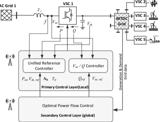
Fig. 1 shows the proposed hierarchical control structure, which mainly includes the droop-based primary and power flow-based secondary control. The droop-based primary control is achieved by the proposed URC, which is elaborated in Section 3. The secondary control layer determines the appropriate set points for the VSC stations periodically based on a transmission loss minimisation algorithm, and give operation mode orders to the primary control based on the states (normal or fault) of all the terminals. The URC executes the orders of the secondary control.
The most adopted operation modes for VSCs in HVDC systems are dc voltage control, frequency control, and voltage droop control. Offshore VSC stations send power to the dc systems following the wind status by performing frequency control, while onshore stations commonly work in voltage control mode or voltage droop mode in traditional proposals for the power balance of the dc systems. In this manner, the wind generation and dc transmission systems act as feeder of the ac systems, while has not response to ac grid frequency changes. This feature has been favoured previously because of the capability of isolating the perturbation or fault in one ac area and prevent the fault propagation to the MTDC grid or another ac area, thus avoid the complication or instability of the whole ac–dc network.
However, ancillary services for both ac and dc grids are expected nowadays [21], and the support to ac grid frequency is becoming
necessary, especially in cases when MTDC grids are integrated to the ac power system in a large scale or when the connected ac grid has low inertia. Therefore, control modes considering ac frequency support are required, and in the meantime the interaction dynamics among different areas needs to be analysed to avoid the negative impacts of the frequency droop and voltage droop. In general, the operational modes of VSC stations considering requirements of not only dc but also ac grid are listed below.
2.1 Frequency/power control
Because of the grid forming ability of the VSC, islands such as wind farms and oil or gas platforms can be connected to VSC-based MTDC networks without auxiliary equipment [22]. For doing this, the associated VSCs (like VSCs 3 and 4 in Fig. 1) will perform
frequency and power control and fix the load frequency. In
addition, if the VSC bears a dominant share of the generation for the connected island ac grid, it also needs to perform frequency control.
2.2 P–Vdcdroop control
In this operation mode, the VSC exerts active power control, while the power order is determined by the powerflow programme and adjusted by the droop control algorithm. This mode is applicable to onshore VSC stations like VSCs 1 and 5 in Fig. 1.
Compared with thefixed active power control, the operation with droop characteristics is critical for the stabilisation of the MTDC grid by adjusting the power delivery as a function of the actual dc link
voltage. The droop slope can be specified considering the
steady-state voltage range of the dc grid and the power processing constraint that is applied to each VSC [10].
2.3 DC voltage control
The VSC operating in this mode performsfixed dc voltage control. Commonly, the VSC that connects to a large ac grid works in this control mode to take as much share as possible in holding the power balance within the MTDC grid. The dc link voltage is
regulated to afixed value under the assumption that the VSC can always balance the power importing to and exporting from the dc grid by adjusting its power injection to the ac grid. However, this assumption cannot always be fulfilled considering the limited capacity of the VSC stations. In practice, the limitations of the power or dc current has to be added to make the power saturated under severe faults [23–25].
2.4 P–f droop control
This mode is as an alternative to theP–Vdcdroop operation, oriented to the scenario when the ac grid that the VSC connects has insufficient inertia, and in the meantime the VSC is connected to a strong node in the MTDC grid. In this mode, the point of view is put at ac side, and the VSC is deemed to be a generation unit with not only grid feeding capability but also grid supporting feature. The VSC 2 in Fig. 1 can especially work in this control mode considering the insufficient inertia of the oil and gas platform.
2.5 Vdc–f interaction control
For the grid of the future, when MTDC systems are largely penetrated into the mains, the regulation of both dc voltage and ac frequency shall be considered in the design of primary or
secondary control layers. To head towards the automation, the primary control of VSC with automatic responses to both dc
voltage and ac frequency could be of interests. A voltage–
frequency double droop control mode is considered in the proposed controller. The future onshore VSC stations (like VSCs 1 and 5 in Fig. 1) can work in this mode for supporting the ac system as well as stabilising the dc system. Besides, the tendency to dc support or ac support can be adjusted simply by scheduling the control parameters.
3
Unified reference controller
With the capability of switching the operation mode of VSCs, the grid of future will manage to automatically adapt to the perturbations in primary sources and loads, and even get through the fault contingencies. For instance, when a VSC station needs to contribute more in the voltage control after the fault of another VSC station, it can change from the voltage droop control to voltage control.
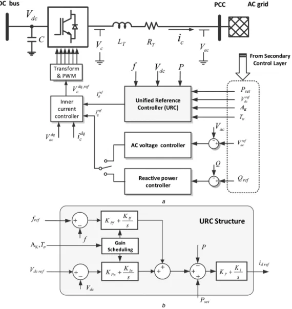
Fig. 2 shows the proposed primary control architecture of the VSC, which is mainly characterixed by the URC. This control architecture is proposed as a unified approach for controlling
VSCs in MTDC grid. The control layers shown in Fig. 2a are
Fig. 2 Primary control for VSC stations aGeneral control architecture
similar to the typical control scheme of VSC-HVDC, which consists of the inner current controller and the outer controllers. The reference of the current indaxis (irefd ) is determined by the URC, which is
dependent on the local measurements and the secondary
commands. The reference of the current in q axis (irefq ) is determined by either the reactive power controller or the ac voltage controller.
The structure of the URC is shown in detail in Fig. 2b.Psetis the power order obtained by the power flow programme, and Ak is the parameter matrix shown in (1). As shown in Fig. 2b,KPfis the proportional gain for frequency control, KIfthe integral gain for frequency control, KPu the proportional gain for voltage control,
KIuand the integral gain for voltage control.
Ak =
KPf KIf KPu KIu
(1)
The elements in the matrixAkmight be zero or non-zero in different control modes, and it will always contain zero element to avoid control fighting. With different configuration in Ak, the URC performs different functions, thus assign the required operation mode to the controlled VSC and for operation modes like Vdc control orfcontrol,Psetneeds to be set to zero.Ttris the transition time, and the gain scheduling block will adjustAkto the objective during the transition time.
Except for thefixed power control, other operation modes can be selected and are generalised as follows:
Mode A: fcontrol:KPf≠0,KIf≠0,KPu= 0,KIu= 0. Pref = KPf+KIf s fref−f (2)
Mode B: P–Vdcdroop control:KPf= 0,KIf= 0,KPu≠0,KIu= 0.
Pref =Pset+KPu(Vdc−Vdc ref) (3)
Mode C: Vdccontrol:KPf= 0,KIf= 0,KPu≠0,KIu≠0. Pref = KPu+KIu s Vdc−Vdc ref (4)
Mode D: P–fdroop control:KPf≠0,KIf= 0,KPu= 0,KIu= 0.
Pref =Pset+KPffref−f (5)
Mode E: Vdc–fcontrol:KPf≠0,KIf= 0,KPu≠0,KIu= 0.
Pref =Pset+KPffref−f+KPuVdc−Vdc ref (6)
4
ac
–
dc interaction and inertia sharing
As a traditional discipline, the HVDC system simply plays the role of a feeder for the ac grids, and only the stabilisation of the dc side is considered. Based on the proposed URC, when the mode A, D or E is activated, the perturbations in the ac side will also be treated. However, the ac perturbations will affect the dc link voltage, and in turn the frequencies of other ac grids. Because of this coupling dynamics, the strength of different areas can be shared to damp the disturbances in the whole network, while on the other hand the perturbations might also be propagated and even amplified and cause instability. The latter situation has to be avoided through a proper design.
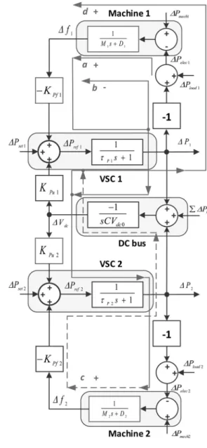
Based on the proposed strategy, the interaction between the dc and ac grid is modeled in Fig. 3. In this analysis, two ac systems are interconnected through the MTDC grid, where two VSCs act as the interface. The ac system is represented by the swing equation of synchronous machine, where the electrical power equals to the load power subtracting the power injected by the power converter station. The dynamics of the power converter is represented by a first-order time delay, and the dynamics of the MTDC grid is determined by the equivalent capacitance of the capacitors. The following analysis gives an example to show that the highlighted droop parameters Kpf1andKpu2should be determined considering the dynamics of the relevant ac systems, which are expressed in the highlighted blocks for the Machines 1 and 2. The arrows in the figure denote the directions that the disturbances flow in the following analysis. The symbols ¨a¨, ¨b¨, ¨c¨ and ¨d¨ represent different effect in presence of disturbances, which are explained in detail in the following analysis.
In Fig. 3,tP
iis the time constant of the power control loop of VSC
i,DPiis the incremental power that is injected to the ac gridi,DPloadi
is the incremental load changes in the ac grid i, Mi and Di,
respectively, the torque and damping parameters of the
synchronous machine that forms the ac grid i, DPk the sum of the power that is injected to other ac grids except for grids 1 and 2, andCthe equivalent dc link capacitance.
As shown in Fig. 3, the system is a multi-input multi-output
system. The power delivery by the VSCs are influenced by
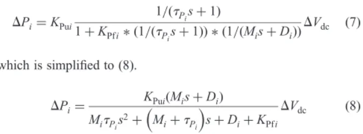
different inputs. During the operation of MTDC grid, the variation in dc voltage can happen due to the events such as the variation in the harvested wind power and the variation in the power injected to the ac grids. To study the response of the power delivery by the VSCs under the variation of dc voltage, the transfer function considering the partial derivation ∂Pi/∂Vdc needs to be obtained. By defining the dc voltage as the variable and the power injected to grid i (1, 2, …) as the function, the transfer function can be written as DPi=KPui 1/(tPis+1) 1+KPfi∗(1/(tP is+1))∗(1/(Mis+Di)) DVdc (7) which is simplified to (8). DPi= KPui(Mis+Di) MitP is 2+ M i+tPi s+Di+KPfiD Vdc (8)
As shown in (8), the power processed by the VSCs is able to oppose the deviation of dc voltage. The opposing effect is stronger whenKPu becomes greater and when KPf becomes smaller. This effect is visualised in Fig. 6cand explained in the next section of the paper. The variation in the frequency of one ac grid is also able to happen due to the events such as the ac load changes and the variation of generation, the response ofDPi in presence of frequency changes is written as DPi= −KPfi 1/(tPis+1) 1+(1/(tP is+1))∗KPui∗(1/CVdc0s) Dfi (9) which is simplified to DPi= −KPfiCVdc0s tPiCVdc0s 2+CV dc0s+KPuiD fi (10)
As shown in (10), the power processed by the VSCiis also able to oppose the deviation of ac frequency in transient states. Moreover, this opposing effect is not only limited in transient when the influence ofDP2andDPk is taken into account.
It is shown in Fig. 3 that the frequency variations of one ac grid can propagate to another ac grid via affecting the dc voltage. The response of frequency of one ac grid in presence of dc voltage changes is written as Dfi=KPui (1/(tPis+1))∗(1/(Mis+Di)) 1+KPfi∗(1/(tP is+1))∗(1/(Mis+Di)) DVdc (11) which is simplified to Dfi= KPui MitP is 2+ M i+tPi s+Di+KPfiD Vdc (12)
Then the interaction between two ac areas is analysed. In the conventional control paradigm, the VSC station does not possess frequency response, and the frequency hence swings freely following the load changes and charactersed by the inertia constant of the generation plant. This effect is denoted by‘a’in Fig. 3. So if the demandPload1 reduces, the frequencyf1increases according to this effect. But in cases when the Mode A, D or E is activated,
Kpf1 is enabled, and the effect ‘a’ will be superposed by a feedback effect which is denoted by‘b’ in Fig. 3, which opposes and damps the frequency variation. Due to the dc voltage increase caused by the decrease of the injected powerP1, the disturbances of the frequency of another ac area f2 can take place if KPu2 is enabled and if the inertia M2 is insufficient, and this effect is
denoted by ‘c’ in Fig. 3. Furthermore, if KPf2 and KPu1 are enabled, the effect‘d’will take place to oppose the effect‘b’. The response off1will be the aggregated effects of‘a’,‘b’and‘d’.
As a healthy interaction among multi terminals, the effects‘c’and ‘d’need to be avoided, which can be achieved under either of the two conditions: sufficient inertia of grid 2, or enough small value ofKPu2. In the former condition, the disturbances in grid 1 will sink in grid 2 due to the inertia of grid 2, showing the effect of inertia sharing. And in the latter condition, the disturbances in grid 1 will not propagate to grid 2 despite that grid 2 could have insufficient inertia.
In general, the conceptual operation paradigm for MTDC grids is shown in Fig. 4, where five different ac areas are interconnected through an MTDC grid. Grid 1 is an oil and gas platform as a low-inertia ac grid, Grids 2 and 3 are offshore wind farms, Grid 4 is an onshore grid with clusters of synchronous machines, and Grid 5 is similar to Grid 4 but with larger rotating mass. According to the different status of each ac grid, different operation mode is selected. In detail, the offshore farms work with frequency control (Mode A), Grid 5 performs voltage droop control (Mode B), the oil and gas platform performs frequency droop control (Mode D), and Grid 4 performs Vdc–f interaction (Mode E).
The arrows in Fig. 4 denote the direction of the disturbanceflow (not necessarily the direction of power flow). In this way, the disturbances in Grids 1, 2 and 3 can sink in Grids 4 and 5, and the disturbances in Gird 4 can also be damped by Grid 5. It can be seen that by operating in a proper mode, the nodes connected to low-inertia ac grids will not be involved in dc voltage control, but only support ac frequency. One VSC station connected to a large ac grid can perform dc voltage control. And several other stations can perform frequency support as well as voltage support following both needs of dc and ac side.
The advantages of the inertia sharing are generalised as
† Frequency support of an ac area by exchanging power with
another ac area that has a greater amount of inertia.
† Isolation of the perturbations at the dc side from affecting the frequency of a low-inertia ac grid.
† Adjustable interaction between the dc voltage and ac frequency at each terminal.
5
Results
A simulated MTDC grid based on CIGRE B4 grid is built as shown in Fig. 5, where two offshore grids and two onshore grids are
interconnected by five VSC stations. The proposed URC is
implemented for each VSC.
The grid B0 is configured to be a strong ac grid with considerable amount of inertia that leads to a stiff frequency. For the sake of simplicity and to have a stiff grid, a Thevenin model (voltage source with impedance) is used to form the grid B0. The VSC Cb-B1 and Cb-B2 are hence assigned to voltage droop control.
Fig. 4 Conceptual operation paradigm for MTDC grid based on ac–dc interaction
The offshore VSC stations Cb-C2 and Cb-D1 perform frequency control. The VSC Cb-A1 works in different control modes with different control parameters in the following tests. The control parameters of VSC station Cb-A1 are shown in Table 1. The base power for VSCs and the base voltage for dc buses are 1200 MW and 800 kV, respectively. Two synchronous machines supply the gridA0 with the base power of 400 and 200 MW. They both have the inertia constant 3.6 s and initially work at 0.72 pu. The events considered in the tests are listed in Table 2.
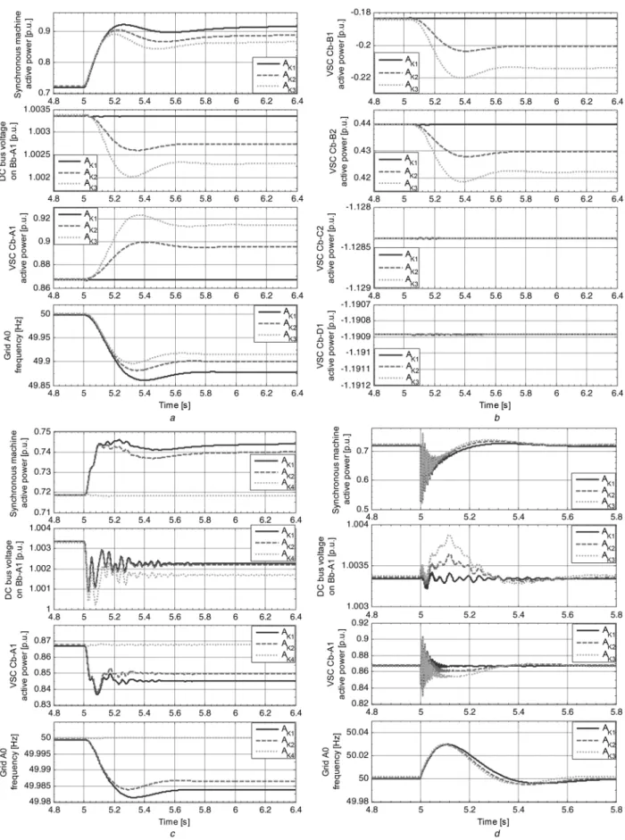
5.1 Responses to different types of disturbances in the network
The results are presented to show the interaction between the dc and ac grids. Firstly, the event E1 is triggered, where a sudden loss of the mechanical power of the 200-MW synchronous machine in gridA0 takes place, and the results based on different control parameters are shown in Figs. 6aandb. Fig. 6ashows that the other generator (400 MW) increases the output power to keep the power equilibrium. Due to the drop of the frequency, the VSC also increases its injected power to contribute to the frequency stabilisation, which is companied by the drop of the dc voltage. Comparing different profiles in each scope, it is found that the ac grid supporting effect
can be enhanced by increasing the value of KPf, with the
compromise of the dc voltage drop. As shown in Fig. 6b, the support of grid frequency is actually an aggregated effect of multiple nodes. The decrease of the dc bus voltage results in the change of the power injection by VSC Cb-B1 and Cb-B2, and the VSC Cb-C2 and Cb-D1 maintain the power import following the frequency control. It shows in the last scope of Fig. 6athat the frequency deviation of the ac grid can be alleviated by properly dispatching the control modes and parameters to the relevant VSCs, and the VSCs that are connected to wind farms are not affected as shown in the third and fourth scopes of Fig. 6b. In this way, the frequency of the gridA0 becomes stiffer as if the grid has greater amount of inertia, which actually relies on the dc voltage support of the VSC that is connected to the gridB0. Since the grid
B0 has sufficient amount of inertia, its frequency will not be much affected by the voltage disturbances. The gridB0 shares its inertia to the gridA0 in this case.
Then the second event E2 is applied, where a step increase of 100 MW in the load on the dc bus Bb-B1 takes place. This event might represents the dc grid perturbations caused by the change of the power import from the offshore wind farms or power injections in one of the onshore terminals. Fig. 6c shows the
responses of the ac grid A0 and VSC Cb-A1. Comparing different profiles in each scope, the effect ofKPuand KPfare both shown, corresponding to the dc and ac droop support. Because of the disturbances triggered by the load increase, the voltage on the dc bus Bb-A1 drops and reaches a new steady state, as shown in the second scope of Fig. 6c. As a result, the power injected to the ac grid by the VSC Cb-A1 decreases to oppose the drop of the dc bus voltage, as shown in the third scope of Fig. 6c. Comparing the profiles ofAk2andAk4in the third scope of Fig. 6c, it is seen that the profile ofAk2has a more significant response. Then comparing the profiles of Ak2 and Ak4 in the second scope of Fig. 6c, it is seen that the profile ofAk2drops less. Therefore, it is demonstrated that a greater value ofKpu enhances the voltage support effect of the VSC. By the similar way to compare the profiles ofAk1 and
Ak2in Fig. 6c, it is shown that a smaller value ofKpfenhances the voltage support effect. By specifying different ratios for KPuover
KPf, the dc voltage droop support and ac frequency droop support can be achieved at different levels.
In the scenarios shown above, the load changes in the dc grid or ac grid A0 can lead to the drop of dc voltage or ac frequency. By configuring the associated VSC stations to the appropriate operation modes with a specified ratio ofKPuover KPf, the perturbations at grid A0 or dc side can be considerably damped by exchanging power with the VSC stations that are connected to the grid B0. The frequency of the offshore ac grids are not affected since the wind power import only follows the frequency of the offshore ac grids in spite of the dc grid voltage. The large grid B0 acts as the sink of the perturbations thanks to its relatively large amount of inertia.
Fig. 6dshows the results in presence of event E3, where one of the two paralleled transmission lines between Ba-A0 and Ba-A1 is broken and totally lost. Since the line reactance instantly increases, the power supplied by the synchronous machine of the grid A0 and the power injected by the VSC Cb-A1 both instantly reduce, resulting in the transient in dc voltage and frequency of Grid A0. The tradeoff between the dc voltage support and ac frequency support is shown by the profiles based on differentKPf. Under a larger value of KPf, the settling time of grid frequency is smaller while the deviation of dc voltage is larger.
5.2 Transition between different operation modes
To show the capability of the URC in smoothly switching among different operation modes, the following tests are conducted. It is worth noting that the mode transitions in this section are intentionally triggered only to demonstrate the capability of the URC. Fig. 5 CIGRE MTDC grid
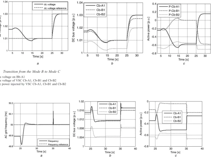
In thefirst case, the eventE4 is applied, where the operation mode of VSC Cb-A1 transits from the Mode B (voltage droop control) to Mode C (voltage control). This action might be needed when the
VSC station that applies the dc voltage control is blocked after a fault, and another station hence needs to take more share in dc voltage control.
Fig. 6 MTDC grid response to different disturbances
aResponses of gridA0 and VSC Cb-A1 when part of the generation is suddenly lost bResponses of other VSCs when part of the generation is suddenly lost
cResponse of the MTDC grid when the dc load on Bb-B1s increases in a step
The transition starts at t= 5 s, and the parameters matrixAk is linearly ramped to the objective values during 10 s. The dc voltage is driven and attached to its reference value after the transition as shown in Fig. 7a. A step change in the dc voltage reference is given att= 25 s, and an effective voltage control is achieved. It is shown in Fig. 7bthat the dc voltage on other nodes (Cb-B1 and Cb-B2) accordingly moves to the new operation points after the change in operation mode and the change in voltage reference. When the dc bus voltage of VSC Cb-A1 changes, the power it delivers changes as well. Following the voltage droop control, the
active power injected by VSC Cb-B1 and Cb-B2 change to achieve the new power equilibrium as shown in Fig. 7c.
In the second case, the eventE5 is applied, where the operation mode of VSC Cb-A1 transits from the Mode E (Vdc–fcontrol) to Mode D (frequency control). The transition starts att= 25 s and arrive to the new operation mode during 5 s. By changing the injected active power, the frequency is regulated to its reference value after the transition as shown in Fig. 8a. The change of the injected power of the VSC Cb-A1 results in the change of the dc voltage as shown in Fig. 8b. And the power injected by the VSC Cb-B1 and Cb-B2 accordingly change following the voltage droop control as shown in Fig. 8c. Att= 35 s, a step decrease of 300 MW load in the gridA0 is triggered, and Fig. 8ashows the transient of the frequency of the grid A0. Thanks to the effective control in Mode D, the VSC Cb-A1 compensates the power imbalance by reducing the power injection from 0.5 to 0.25 p.u. as shown in Fig. 8c, and the frequency is drawn back to its reference after a short transient. From Figs. 8bandcit can be seen that the other VSCs also move the operation point to the restore the power equilibrium.
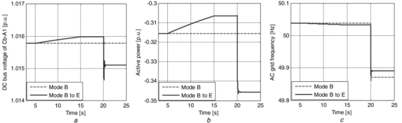
In the third case, the operation mode of VSC Cb-A1 transits from the Mode B (voltage droop control) to Mode E (Vdc–fcontrol). The transition starts at 5 s and arrive to the new operation mode during 10 s. The dc voltage and injected active power are seen to move to the new operation point in Figs. 9a and b, respectively. A step increase of 300 MW load in the grid A0 takes place at 20 s, and the dc voltage and active power accordingly change to compensate the load. In contrast, the responses when the VSC works in Mode B are also plotted, and the dc voltage and injected active power have not significant responses in presence of ac load changes. Fig. 9cshows the effect of the frequency support under the Mode E compared with the Mode B.
Table 2 Events in the tests
Event Description
E1 total loss of mechanical power of the 200-MW synchronous machine in grid A0
E2 step increase of 100 MW load on bus Bb-B1
E3 break of one of the transmission lines between Ba-A0 and Ba-A1 E4 transition from the Mode B (voltage droop control) to Mode C
(voltage control)
E5 transition from the Mode E (Vdc−fcontrol) to Mode D (frequency
control) Table 1 Control parameters for VSC Cb-A1
Parameter KPu KPf
sAk1 20 0
Ak2 20 0.4
Ak3 20 0.8
Ak4 0 0.4
Fig. 8 Transition from the Mode E to Mode D aFrequency of the Grid A0
bdc bus voltage of VSC Cb-A1, Cb-B1 and Cb-B2
cActive power injected by VSC of VSC Cb-A1, Cb-B1 and Cb-B2 Fig. 7 Transition from the Mode B to Mode C
adc bus voltage on Bb-A1
bdc bus voltage of VSC Cb-A1, Cb-B1 and Cb-B2 cActive power injected by VSC Cb-A1, Cb-B1 and Cb-B2
The results shown in Figs. 7–9 exhibit the effectiveness of the proposed unified control structure in re-dispatching the role of a VSC station.
6
Conclusion
In this paper, the operation of MTDC grids with inertia sharing was discussed, supported by the proposed URC. The perturbations in the ac–dc grids were able to be damped by sharing the inertia of one or multiple large ac grids without interfering the low-inertia ac grids. In this way, the requirements of the connected ac grids can also be met as well as the balance of energy in the MTDC grid, and the large-scale integration of offshore wind energy based on MTDC grid becomes more possible thanks to its support to the connected ac grids. Simulation results based on the CIGRE test grid model showed good performance and merits of the proposed solution. Each VSC station in the MTDC grid had a satisfactory response to the events such as load changes in ac grid, load changes in dc grid and transmission line fault. Besides, the proposed URC is demonstrated to be effective in control mode transition, and it will further make the VSC stations have the potentials for automatic dispatch, operation and fault restoration, once the associated secondary control is equipped.
7
Acknowledgment
This work has been partially supported by the Spanish Ministry of Economy and Competitiveness under the project ENE2014-60228-R. Any opinions,findings and conclusions or recommendations expressed in this material are those of the authors and do not necessarily reflect those of the host institutions or funders.
8
References
1 Schettler, F., Huang, H., Christl, N.:‘HVDC transmission systems using voltage sourced converters design and applications’. Power Engineering Society Summer Meeting, 2000, pp. 715–720
2 Adam, G.P., Williams, B.W.: ‘Multi-pole voltage source converter HVDC transmission systems’,IET Gener. Transm. Distrib., 2016,10, (2), pp. 496–507 3 Feldman, R., Tomasini, M., Amankwah, E.,et al.:‘A hybrid modular multilevel
voltage source converter for HVDC power transmission’, IEEE Trans. Ind. Appl., 2013,49, (4), pp. 1577–1588
4 Li, Y., Zhang, Z.W., Rehtanz, C.,et al.:‘A new voltage source converter-HVDC transmission system based on an inductivefiltering method’,IET Gener. Transm. Distrib., 2011,5, (5), p. 569
5 Shariat Torbaghan, S., Gibescu, M., Rawn, B.G.,et al.:‘Investigating the impact of unanticipated market and construction delays on the development of a meshed HVDC grid using dynamic transmission planning’,IET Gener. Transm. Distrib., 2015,9, (15), pp. 2224–2233
6 Van Hertem, D., Ghandhari, M.:‘Multi-terminal VSC HVDC for the European supergrid: obstacles’,Renew. Sustain. Energy Rev., 2010,14, (9), pp. 3156–3163 7 Axelsson, U., Vatten, H., Liljegren, C.,et al.:‘The gotland HVDC light project– experiences from trial and commercial operation’. 16th Int. Conf. and Exhibition on Electricity Distribution, 2001, pp. 18–21
8 Gordon, B.S.:‘Supegrid to the rescue’,Power Eng., 2006,20, (5), pp. 30–33 9 Rao, H.:‘Architecture of Nan’ao multi-terminal VSC-HVDC systems and its
multi-functional control’,CSEE J. Power Energy Syst., 2015,1, (1), pp. 9–18 10 Barker, C.D., Whitehouse, R.:‘Autonomous converter control in a multi-terminal
HVDC system’. Ninth IET International Conf on ACDC, 2010, pp. 1–5 11 Berggren, B., Majumder, R., Sao, C.,et al.:‘European patent specification: method
and control device for controlling powerflow within a DC power transmission network’, 2010
12 Liang, J., Jing, T., Gomis-Bellmunt, O., et al.: ‘Operation and control of multiterminal HVDC transmission for offshore wind farms’,IEEE Trans. Power Deliv., 2011,26, (4), pp. 2596–2604
13 Guan, M., Pan, W., Zhang, J.,et al.:‘Synchronous generator emulation control strategy for voltage source converter (VSC) stations’,IEEE Trans. Power Syst., 2015,30, (6), pp. 3093–3101
14 Zhang, W., Rouzbehi, K., Luna, A.,et al.:‘Multi-terminal HVDC grids with inertia mimicry capability’,IET Renew. Power Gener., 2016,10, (6), pp. 752–760 15 Zhu, J., Guerrero, J.M., Hung, W.,et al.:‘Generic inertia emulation controller for
multi-terminal voltage-source-converter high voltage direct current systems’,IET Renew. Power Gener., 2014,8, (7), pp. 740–748
16 Silva, B., Moreira, C.L., Seca, L., et al.: ‘Provision of inertial and primary frequency control services using offshore multiterminal HVDC networks’,IEEE Trans. Sustain. Energy, 2012,3, (4), pp. 800–808
17 Marten, A., Westermann, D.:‘Load frequency control in an interconnected power system with an embedded HVDC Grid’. IEEE Power and Energy Society General Meeting, 2012, pp. 1–7
18 Haileselassie, T.M., Torres-Olguin, R.E., Vrana, T.K.,et al.:‘Main grid frequency support strategy for VSC-HVDC connected wind farms with variable speed wind turbines’. IEEE PES PowerTech, 2011, pp. 1–6
19 Rouzbehi, K., Miranian, A., Luna, A.,et al.:‘A generalized voltage droop strategy for control of multi-terminal DC grids’,IEEE Trans. Ind. Appl., 2013,51, (1), pp. 59–64 20 Rouzbehi, K., Miranian, A., Luna, A.,et al.:‘DC voltage control and power sharing in multiterminal DC grids based on optimal DC power flow and voltage-droop strategy’,IEEE J. Emerg. Sel. Top. Power Electron., 2014,2, (4), pp. 1171–1180 21 Van Hertem, D., Renner, R.H.:‘Ancillary services in electric power systems with
HVDC grids’,IET Gener. Transm. Distrib., 2015,9, (11), pp. 1179–1185 22 Vrana, T.K., Torres-Olguin, R.E., Liu, B.,et al.:‘The North Sea super grid–a
technical perspective’. Ninth IET Int. Conf. on AC and DC Power Transmission, 2010, pp. 1–5
23 Dierckxsens, C., Srivastava, K., Reza, M.,et al.:‘A distributed DC voltage control method for VSC MTDC systems’,Electr. Power Syst. Res., 2012,82, (1), pp. 54–58 24 Xu, L., Yao, L.:‘DC voltage control and power dispatch of a multi-terminal HVDC system for integrating large offshore wind farms’,IET Renew. Power Gener., 2011,
5, (3), p. 223
25 Haileselassie, T.M., Molinas, M., Undeland, T.: ‘Multi-terminal VSC-HVDC system for integration of offshore wind farms and green electrification of platforms in the North Sea’. Proc. NORPIE, 2008, pp. 1–8
Fig. 9 Transition from the Mode B to Mode E adc bus voltage on Bb-A1
bActive power injected by the VSC Cb-A1 cFrequency of the grid A0