Airport Layout Planning
0754074
Abstract
Airport layout planning is a highly complex discipline which requires much forethought, as inadequate or suboptimal solutions could be both dangerous and costly. However, designing a good airport requires compromises between the requirements of all stakeholders involved, ranging from aviation authorities and airlines to passengers and nearby residents. This is a highly delicate issue as evidenced by current airport extension proposals in the UK, including Heathrow and Stansted airports. Although airport planning tools exist, no tool presently allows multiple stakeholders to observe and interact with a single airport planning model, allowing them to evaluate a proposed layout from different points of view. This paper aims to illustrate the applicability of Empirical Modelling concepts to such a process, by constructing and demonstrating the use of an airport model.
1
Introduction
1.1
Overview
Airport planning is a complex, time-consuming and highly costly process. Countless rules, regula-tions and physical restricregula-tions govern the placement of essential components culminating a complete air-port, such as runways, taxiways and passenger ter-minals, to name a few. Inadequate or suboptimal placement of structures can be extremely costly and in some cases, potentially hazardous. Governing bod-ies such as the UK’s CAA1are responsible for issu-ing and ensurissu-ing adherence to strict guidelines to en-sure airport safety, security, economy, efficiency and longevity.
Given the ever increasing volumes of both passen-ger as well as cargo transport, airports are virtually continually expanding. In 1970 the UK handled 32 million passengers through all its airports; a figure which increased to 180 million by 2000 and is fore-cast to reach 275 million by 20102. The astronom-ical increase in demand for air travel has resulted in rapid airport growth. Unfortunately resources such as space are often limited, thus amplifying any pos-sible ramifications of new airport construction or ex-isting airport expansion. Over the years, computer simulation tools have been used for a wide variety of applications, ranging from nuclear reactor to road traffic network simulation. Airport layout planning is no exception and a myriad of tools have been devel-oped to aid airport planners in designing new or
ex-1Civil Aviation Authority
2Figures taken fromhttp://www.cpe.org.uk
panding existing airports. Products such as those of-fered byTransSolutions3andAirport Research Cen-ter GmbH4 allow planners to model airports prior to construction, in order to evaluate factors ranging from movement of terminal passengers to movement of air-field traffic. These tools provide accurate dimensions and measurements for airport designers, as well as using mathematical techniques to model aspects such as passenger flow through terminal buildings. Such simulations help mitigate inadequate planning prior to actual construction and have proven useful within predefined scope.
Designing something as complex as a modern air-port is not a trivial task, as a multitude of stake-holders must be taken into consideration. A design plan that constitutes agoodairport can be seen as a set of compromises between all stakeholders, which can include any persons or organisations such as the CAA, the government, airport owners, airport work-ers, airlines, passengers and residents living nearby. In some cases, stakeholders’ goals coincide, while in other cases they might conflict. More importantly, it must be recognised that stakeholders view any pro-posed solution from entirely different points of view. For example, the CAA might require that departing aircraft on a taxiway maintain a minimum separation distance of200mwhile airport owners might want to maximise the potential passenger throughput. On dif-ferent but nonetheless valid notes, passengers might want minimal queues once inside the terminal build-ing, while nearby airport residents might want min-imal visual impact of the airport on the surrounding
3http://www.transsolutions.com/ 4http://airport-consultants.com/
environment. A present example is the recent expan-sion of London’s Heathrow Airport to include a fifth terminal, with ongoing discussions between stake-holders for the construction of a third runway.
It was previously stated that existing simulation tools have proven highly effective tools for airport planning. What they do not provide however is, for any given aspect, a tool able to cater for the perspec-tives of all the model stakeholders. As a result, while not necessarily a full replacement for traditional sim-ulation approaches, Empirical Modelling (EM) has much to offer in terms of airport planning. By con-structing and maintaining dependencies between air-port components, a significant air-portion of the layout design process is automated on behalf of the user. Such an example might be the requirement of a fire service station to be present within half a mile of any given point on a runway, or for every runway to in-clude a runoff at least a certain percentage of the run-way’s length. EM would allow designers to perform simulations in virtual environments which would oth-erwise be impossible. As outlined in Beynon (2005), interaction with an environment representing a real-life environment constructed based upon observa-tion, allows users to mimic potential real life situa-tions. Safety concerns regarding minimum run-off, approach visibility, maximum aircraft wingspan and permissible runway payload, runway lighting, run-way dimensions and separation distances are all re-strictions which EM easily allows to be taken into ac-count. Such a model could also allow potential pas-sengers to ensure accessibility or washroom facilities are always within easy access within any part of the terminal building, or nearby residents to evaluate dif-ferent airfield layouts such as to minimise noise or visual impact.
1.2
Objectives
The primary objective of this project is to demon-strate proof of concept for the application of EM to airport layout planning by constructing and demon-strating an empirical airport model. The scope of this is to develop a tool which could theoretically allow multiple stakeholders to view and interact with a sin-gle model in order to achieve different goals. The implementation of an airport planning model could be restricted to2-D or3-Dvisualisation, or simula-tion of airport interacsimula-tion. Since the extent of such a project’s possibilities is extremely diverse and due to time constraints, this study shall be limited to a high-level placement of primary airport buildings and
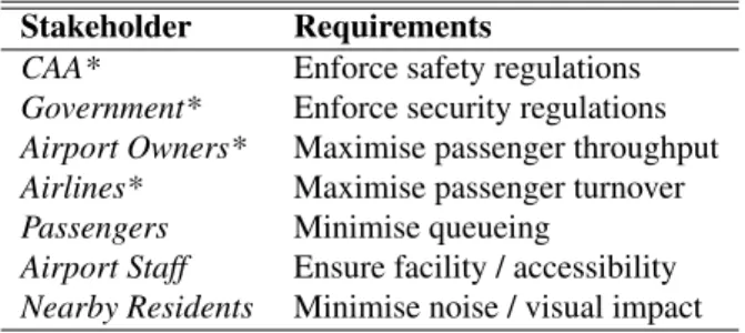
Stakeholder Requirements
CAA* Enforce safety regulations
Government* Enforce security regulations
Airport Owners* Maximise passenger throughput
Airlines* Maximise passenger turnover
Passengers Minimise queueing
Airport Staff Ensure facility / accessibility
Nearby Residents Minimise noise / visual impact Table 1: Airport stakeholders
components in2-Donly.
2
Empirical Modelling
2.1
Real-World Application
One of the greatest strengths of EM is the ability to construct open, experimental and experiential in-teractive environments. EM tools allow for the con-struction of models of real-world environments by observation. This is especially useful in situations where domain knowledge is incomplete, giving rise to a pre-theory experimentation approach, simply by modelling state. With regards to airport layout plan-ning, a model can be created to represent the various components that constitute an airport. This process is based on experimental observations, as outlined in Beynon and Cartwright (1990), albeit the agents’ abilities within the model shall not be restricted de-pending on their perspective in the design process. However, the power of the model is its ability to pro-vide a human computing interface in order to allow for the design of agoodairport. But how can this be achieved?
EM provides the ability to model a situation or en-vironment with different motivations. Table 1 pro-vides a list of airport stakeholders, each of which ob-serves different aspects of and has different expecta-tions of a potential airport. All are different but all are equally relevant and important. To create a suitable model, each of these aspects must be properly mod-elled in a definitive script. A given definitive script can be categorically analysed given three different as-pects;observables,dependencyandagency.
2.1.1 Observables
Observables are entities whose state can be cap-tured by experiment. In the case of airport planning,
the observables shall be the various airport compo-nents, including runways, taxiways, terminal build-ings, amongst others. An airport must consist of a minimum set of these buildings for core functional-ity. As an airport expands, different buildings may be added as required. Implemented observables are restricted only by the model granularity and as such may represent something as broad as a runway or as specific as an individual sign inside a terminal build-ing.
2.1.2 Dependency
Dependency defines the relationship and con-straints that must be maintained between observables. The list of dependencies in an airport is largely gov-erned by restrictions and guidelines outlined by or-ganisations such as the CAA. These relationships might be the mandatory presence of firefighting facil-ities within50mof any building or to have separate bathroom facilities for every1,000 people inside a terminal building.
2.1.3 Agency
An agent is anything that can change the current state of any of the entities or observables within the model. The predominant agents within the airport layout planning model shall be the modellers, or the stakeholders of the model as outlined in Table 1.
The aim of this project is to develop a script of def-initions in an attempt to capture the interests of stake-holders and represent them in a relevant and consis-tent model environment, through which an action or requirement of one may be immediately interpreted and understood from all other points of view. Given that the scope of this model shall be limited to certain building types, the model shall only be applicable to the stakeholders marked * in Table 1.
2.2
Existing Tools
EM is a relatively new field of study and thus the available tools are still somewhat limited. The pri-mary tool currently available istkeden; an inter-preter supporting the use of a range of definitive no-tations, each of which providing different abilities. Without delving into further detail, the chosen nota-tion for the airport planning model shall require the combined use of EDEN, DoNaLD and SCOUT, us-ing similar principles as defined in Beynon and Yang (1990).
2.2.1 EDEN
EDENcan be used to generate a definitive script to monitor certain aspects of the model being developed.
EDENshall be used to check and control constraints that must be observed between various airport build-ing parameters, includbuild-ing size and placement. This is required to trigger certain types of messages as pa-rameters are changed while running the model. 2.2.2 DoNaLD
DoNaLDis a definitive notation for2-Dline draw-ing. DoNaLDallows for the construction of models consisting of simple points and shapes which shall suffice for the visual representation of an airport. The power of DoNaLDallows definitive shapes to have their dimensions and locations defined in relative, rather than absolute terms. In the context of the air-port planning tool, components are able to be defined in terms of each other, thus providing a dynamic feel to the model as parameters are modified.
2.2.3 SCOUT
Lastly, SCOUTwill allow for the construction of a definitive notation defining screen layout. Rather than forcing a user to enter instructions and alter-ations to theDoNaLDscript manually,SCOUTshall provide a view port window to the airport drawn usingDoNaLDand accompanying controls in order to alter the placement of the airport components.
SCOUTshall also be used for displaying of error mes-sages as and whenEDENdetects airport constraint in-fringements.
Unfortunately, much of the tools currently avail-able are incomplete and poorly documented. The de-velopment environments are often difficult to use and error messages are often cryptic and difficult to iso-late. The tools are also somewhat unstable, with some issues appearing to occur non-deterministically mak-ing them difficult to reproduce. Furthermore, inter-facing between various definitive notations including accessing variables is largely inconsistent. Access-ing properties for example fromedentoDoNaLDis different to accessing datavice versa, which is also the case with other definitive notation environments. This makes it extremely awkward to develop models with ease, making model development a highly time consuming process. However, despite the availabil-ity of alternative tools,eden,DoNaLDandSCOUT
shall suffice for the construction of the simple airport model.
3
Model Design
3.1
Overview
Presently there are several commercially available tools for airport planning purposes. The majority of these tools tend to work in isolation, and are restricted to modelling terminal buildings, taxiways or runways alone. These tools are highly effective, but have a single common failure in their inability to model state and generate an experience in a wider sense, to achieve the goals of all stakeholders involved. This section outlines the scope and implementation of the empirical airport model.
3.2
Scope
The scope of the model to be developed is to set up the dependencies between major components that make up an airport, amongst others, this shall include runways, taxiways, terminals, hangars and fuel de-pots. The objectives of the model shall be to allow for dynamic allocation of all airport components in such a manner so as to satisfy the requirements of the stakeholders involved. The model shall begin with a simple airport layout. The user should be free to move around any airport components on screen. However, doing so might result in other components being moved depending on model constraints and de-pendencies.
3.3
Implementation
The model shall consist of a screen which will dy-namically resize its contents depending on the size of the window, based on techniques outlined in Beynon (2007). When being viewed, the top75%of the win-dow is used as a view port viewing area; a top-win-down view of the entire airport being designed. By default, a certain set of airport components are present, how-ever these can be added or removed as required. In the lower portion of the screen there shall be controls to enable the user to move components around the air-port dynamically. The controls also allow the user to resize components such as runways. Whenever any action is taken, all components reaffirm their adher-ence to CAA standards depending on size and loca-tion. The next section is a list of airport components and interdependencies that are ensured by the model. While this list is non-exhaustive in terms of all possi-ble airport buildings, it is sufficient for the purposes of this model. Furthermore, quantitative requirement values are chosen arbitrarily. Should the user decide to modify any of the airport’s building parameters,
they too will be subject to guidelines and dependen-cies which will inform the user if something illegal, dangerous or simply not possible is being implied. The model itself consists of separateairport.d,
events.eandscreen.sscript files for the var-ious notation types, with a single eden script file
run.eto initialise all definitive scripts. 3.3.1 Runway
The runway is the most obvious and recognisable airport component. The implemented model contains two runways by default. The most basic requirements for a runway are length, width and runoff area. A runway’s approach system consists of:
• ILS5: Localiser (horizontal) and glidescope (vertical) must be present in the form of an end-of-runway transmitter.
• Outer, Middle & Inner Marker beacons: Flashing lights to help pilots to judge distance. • Runway approach lighting: Used to illuminate
final approach for landing aircraft. These can be summarised as REIL6(white strobes lights at
end of active runway) and HIRL7 (white lights
at side of runway and red/green end lights indi-cating the end/start of runway).
3.3.2 Runway Designator Board/Lights
Board showing runway ahead (i.e. ‘Runway 09R-27L’ with red lights to show non-active runway and yellow for an active runway). This is important for pilots not used to an airport while clearing for take-off. This is particularly important as accidents have previously occurred due to the lack of such indica-tors, such as the Singapore Airlines accident while taking off from a Taiwan airport in 2000. Tarmac markings are also a critical part of on-ground naviga-tion, including hold-short lines. On taxiways joining runways and crossing other taxiways there are hold-short lines used as marker points, or to give way to other aircraft.
3.3.3 Terminal Building
The terminal building is modelled as a single unit representing all passenger throughput, ranging from baggage check in and gate boarding to arrivals and
5Instrument Landing System 6Runway End Identifier Lights 7High Intensity Runway Lights
baggage retrieval. The terminal building is also cou-pled with aircraft docking bays (gates), initially set to be identical in size, used as aircraft parking bays for loading and unloading. The terminal building must be located within an area with easy access to passen-gers arriving and departing from the airport, as well as easy access to the airfield for aircraft docking. It must also contain adequate building evacuation loca-tions and emergency exit localoca-tions.
3.3.4 Gates
Gates are typically80m×80mdesignated areas sufficiently large to park any commercial aircraft. A gate must consist of an air bridge for passenger board-ing, fuel hose attachments, marker lines for parking and other facilities required by an aircraft for unload-ing or takeoff preparation.
3.3.5 Fire Station
The fire station is a legally required aircraft compo-nent that must be within easy access of any constantly used section of the airfield, in particular the runways and adjacent to the passenger terminal building. 3.3.6 Weighbridge
A weighbridge is used to weigh aircraft before takeoff if load sheet values are unsatisfactory, as well as to check below maximum permissible takeoff weight. A weighbridge must therefore be stationed adjacent or en-route to the start of a runway, prior to takeoff.
3.3.7 Windsock
Despite modern advances in weather radar and other weather monitoring systems, a windsock is still highly important for the pilot to check speed and gusting of the wind prior to takeoff. Windsock re-quirements are relatively simple; a tough, brightly coloured canvas sock measuring approximately 2m long and suspended off a pole5minto the air. These requirements cannot be reflected in our simple model, however the fact that windsock must be visible at the start (takeoff point) of any given runway, can be mod-elled.
3.3.8 Jet Blast Deflectors
Jet blast deflectors are not used everywhere but are usually seen in larger airports. These deflectors are used to stop large amounts of thrust from taxiing air-craft from damaging other structures, and as a result
are only required towards the start of a runway and/or between taxiways adjacent to buildings.
3.3.9 Control Tower & Radar
The control tower houses approach controllers and ground controllers. It is imperative that the control tower is in a clearly visible location in full view over the airport and runways for ground controllers. Al-though this is often accompanied by an additional ‘ground’ tower to aid visibility, the model shall only cater for a main control tower. In addition to the con-trol tower, a radar is also required for long distance visibility as well as short distance visibility in poor condition scenarios.
3.3.10 Fuel Depot
A fuel depot is the main fuel store for all aircraft refuelling. Although it must be within easy access, a fuel depot must have a clear250m radius to avoid unnecessary damage to buildings in the immediate vicinity in the event of an explosion.
Before proceeding any further, a clear distinction must be made between model dependencies and con-straints. Dependencies are aspects of a model which represent relationships between various components. Constraints are physical or environmental restrictions governing the interaction of the airport components, as outlined in Adzhiev et al. (1990). To represent these aspects, a series of Boolean variables shall be present which will monitor changes in the model’s state in real time. As the state of any variable changes, the user will immediately be notified on screen by means of error messages displayed using
SCOUT.
4
Results
4.1
Evaluation
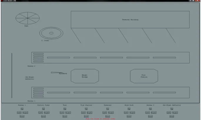
The model was tested using several parameters and many changes were made to the environment state. Figure 1 illustrates a screenshot of alternate airport layout planning models in operation. The developed airport model successfully provides a visualisation of a conceptual representation coupled with func-tional dependencies, in a similar manner to that in Beynon et al. (1990). Moving components such as the Fuel Depot, Control Tower, Runway, Weigh-Bridge or Fire Station around all yield potential user warn-ings. The constructed model is very simple in nature,
Figure 1: Screenshot of model intkeden, usingeden,DoNaLDandSCOUT
and in terms of possible visual control functionality for all possibilities concerning the displayed airport components is not exhaustive. However, the imple-mented functionality is sufficient for proof of concept that EM has the potential to contribute towards airport planning and development.
5
Conclusion
5.1
Critical Summary
Through a relatively simple model it has been shown that it is feasible and realistic to create an airport plan-ning tool. Although the model only reflected the high level placement of common airport components, it can clearly be seen that EM concepts are readily ap-plicable and useful for airport planning. By allow-ing multiple stakeholders to partake in the design and planning of an airport, such a model is able to eval-uate multiple aspects from different points of view on a single model simultaneously. The toolseden,
DoNaLDandSCOUTsuccessfully provided a suitable framework within which such a model could be de-veloped.
5.2
Future Work
The scope of this project was to provide proof of concept that EM does have valid, real-world ap-plications to airport planning. As a result, the im-plemented model was a relatively simple one and there are several additions and improvements to the model that could be implemented. The first of these improvements could be the potential representation of non-visible aspects of an airport, to increase the model’s scope to encompass more stakeholders. This could be done by the representation of line-of-sight and audible distance ranges to evaluate the impact on people living nearby the airport. Another inter-esting addition would be the analysis of the airport under reduced visibility conditions, thus necessitat-ing the placement of adequate lightnecessitat-ing. Other basic improvements could be to allow for the rotation of components in360o.
Additional airport restrictions that could be added include the addition of noise abatement zones; points at which aircraft are requested to throttle back im-mediately after takeoff to reduce noise and pollu-tion, which could be indicated by projected on-screen boundaries. Another important factor would be the addition of control zones restricting airport controlled
airspace. This would be especially useful if the model was expanded on a macro scale to encompass en-croaching control zones from multiple airports.
Having an airport set up, it should eventually be possible for a user to simulate aircraft landing and taxiing to the appropriate locations adjacent to a ter-minal building. Introducing a second aircraft while the first is already present will invoke further de-pendencies of minimum aircraft distances. Once in the correct docking position, aircraft support vehi-cles will need to make their way adjacent to the air-craft to provide ancillary services before the airair-craft is ready to leave once again. Landing aircraft would be subject to minimum separation distances and taxi instructions issued by the control tower. Following these procedures, when contrasting aBoeing 737-300
and anAirbus A380, the latter requires additional pas-senger and baggage handling staff and facilities, in addition to larger docking bays, having landed at an airport. Having successfully unloaded baggage, pas-sengers and crew, these could be replaced by active components as part of the model, such as moving refuelling vehicles etc. Every aircraft that takes off has a different size and weight, thus affecting pro-cedures that must be undertaken at an airport. The CAA also stipulates different procedures for taxi and takeoff depending on aircraft size, which could also be reflected in such an addition. Prior to departure, an aircraft will be required to queue behind all other aircraft also awaiting departure. The model will en-sure that at all times, aircraft respect minimum re-quired horizontal and vertical (post takeoff) distances from each other and on occasion, from airport sup-port vehicles or buildings. Lastly, a useful addition in view of the aftermath following the 11 September 2001 events, focus of the model on a more granular scale to encompass security aspects would be a valu-able addition to the model. A final improvement to the model would be to supplement it with LSD8
func-tionality for superior multi-agent modelling, in order to discriminate and classify observables according to agent.
References
Valery Adzhiev, Meurig Beynon, Alan Cartwirght, and Yun Pui Yung. A new computer-based tool for conceptual design. University of Warwick, 1990. Meurig Beynon. Computational support for realism
8Language for Specification and Design
in virtual environments. University of Warwick, 2005.
Meurig Beynon. Visualisation using empirical mod-elling principles and tools. University of Warwick, 2007.
Meurig Beynon and Alan Cartwright. Agent-oriented modelling for engineering design. University of Warwick, 1990.
Meurig Beynon and Yun Pui Yang. Definitive inter-faces as a visualisation mechanism. University of Warwick, 1990.
Meurig Beynon, Yun Pui Yung, and C. J. Sidebotham. Computer-assisted jigsaw construction: a case-study in empirical modelling. University of War-wick, 1990.