• No results found

n ISA 800T ISA Series Installed Sound Amplifiers User Manual n ISA 280 n ISA 750 ISA Audio Power Amplifiers *TD * TD rev.

N/A
N/A
Protected

Academic year: 2021

Share "n ISA 800T ISA Series Installed Sound Amplifiers User Manual n ISA 280 n ISA 750 ISA Audio Power Amplifiers *TD * TD rev."

Copied!
40
0
0

Loading.... (view fulltext now)

Full text

(1)

User Manual

ISA Audio Power Amplifiers

ISA Series

Installed

Sound

Amplifiers

TD-000093-00 rev.C

*TD-000093-00*

n

ISA 300T

n

ISA 500T

n

ISA 800T

n

ISA 280

n

ISA 450

n

ISA 750

(2)

CAUTION: TO REDUCE THE RISK OF ELECTRIC

SHOCK, DO NOT REMOVE THE COVER. NO

USER-SERVICEABLE PARTS INSIDE. REFER SERVICING

TO QUALIFIED PERSONNEL.

FCC INTERFERENCE STATEMENT

NOTE: This equipment has been tested and found to comply with the limits for a class B digital device, pursuant to part 15 of the FCC rules. These limits are designed to provide reasonable protection against harmful interference in a residential installation. This equipment generates, uses, and can radiate radio frequency energy and if not installed and used in accordance to the instructions , may cause harmful interference to radio communications. However, there is no guarantee that interference will not occur in a particular installation. If this equipment does cause harmful interference to radio or television reception, which can be determined by switching the equipment off and on, the user is encouraged to try to correct the interference by one or more of the following measures:

- Reorient or relocate the receiving antenna.

- Increase the separation between the equipment and the receiver.

- Connect the equipment into an outlet on a circuit different from that to which the receiver is connected. - Consult the dealer or an experienced radio or TV technician for help.

CAUTION

RISK OF ELECTRIC SHOCK DO NOT OPEN

© Copyright 2000, QSC Audio Products, Inc.

QSC® is a registered trademark of QSC Audio Products, Inc. “QSC” and the QSC logo are registered with the U.S. Patent and Trademark Office

The Audio Precision logo is the property of Audio Precision, Beaverton OR All trademarks are the property of their respective owners.

IMPORTANT SAFETY PRECAUTIONS

& EXPLANATION OF SYMBOLS

WARNING: TO PREVENT FIRE OR ELECTRIC SHOCK, DO NOT EXPOSE THIS

EQUIPMENT TO RAIN OR MOISTURE.

The lightning flash with arrowhead symbol within an equilateral triangle is intended to alert the user to the presence of uninsulated “dangerous” voltage within the product’s enclosure that may be of sufficient magnitude to constitute a risk of electric shock to humans.

The exclamation point within an equilateral triangle is intended to alert the user to the presence of important operating and maintenance (servicing) instructions in this manual.

This amplifier has a serial number located on the rear panel. Please write this and the model number down and keep them for your records.

Model: ISA ________________________________ Serial Number:______________________________ Date of Purchase:____________________________ Purchased From:_____________________________

The lightning flashes printed next to the OUTPUT terminals of all ISA amplifiers are intended to alert the user to the risk of hazardous energy. Output connectors that could pose a risk are marked with the lightning flash.

(3)

INTRODUCTION:

ISA Series Overview ...4

Front Panel Illustration ...4

Rear Panel Illustrations ...5

FEATURES & SETUP : Power Switch ...6

Cooling Air Inlet and Exhaust Vents ...6

LED Indicators ...7

Gain Controls ...8

Input Jacks ...8

DataPort V2 Connector ...9

Daisy Chaining to Other Devices from the DataPort V2 ...9

Stereo & Parallel Operating Modes ...10

DIP Switch Settings ...11

Bridge Mono Operating Mode ...12

DIP Switch Settings ...12

Low Frequency Filter ...13

DIP Switch Settings ...13

Frequency Response Curves ...14

Clip Limiter ...15

DIP Switch Settings ...15

INSTALLATION: Rack Mounting ...16

Mounting Dimensions ...16

Cooling Requirements ...17

AC Mains (AC Power) ...17

CONNECTIONS: Inputs: XLR and Terminal Block Input Jacks ...18

Inputs: DataPort V2 Connections and Notes ...19

Outputs: Using the Screw Terminal Connections ...20

Outputs: Direct Low Impedance (2-16 ohm loads) ...21

Outputs: Distributed High Impedance (“T” models only) ...22

Power Sharing Between High and Low Impedance Outputs (“T” models only) ...24

Securing Output Wiring to the Chassis ...25

OPERATION: Gain Controls ...26

AC Power Switch ...26

Front Panel LED Indicators ...26

Normal Operating Levels ...26

APPLICATIONS: General Notes, Distributed Line Principles ...27

Low Frequency Filtering, Distributed Output Examples ...28

Multiple Low Impedance Loads in Series or Parallel Connections ...30

DataPort V2 Application Information ...32

TROUBLESHOOTING ...33

SPECIFICATIONS ...35

WARRANTY INFORMATION ...39

HOW TO CONTACT QSC AUDIO PRODUCTS ...39

3

(4)

FRONT PANEL

(all models)

Thank you for the purchase of your new ISA amplifier. To get the most out of your amplifier, review this manual carefully. The installation, connection and operation sections provide useful guidelines to get you up and running quickly and correctly. The QSC shipping box should contain:

1- The amplifier 2- This user manual

3- #14AWG AC line cord with IEC connector After you have removed the amplifier from the box, make sure you save the box and packing material for safely storing or shipping the amplifier in the future.

The ISA Series amplifiers offer professional-quality perfor-mance at an affordable price. Three power-points are offered in both directly-coupled and autotransformer-coupled output. Output power at 2 ohms ranges from 430 to 1200 watts per channel.

The ISA amplifier was designed to fit your installed sound requirements. The detented gain controls, located on the rear panel, provide accurate, repeatable adjustments. Each channel has defeatable clip limiting and selectable-response low frequency filters. QSC’s rear-to-front airflow cooling helps to keep other system components in the equipment rack cooler, enhancing overall system reliability.

For those systems with QSC DataPort accessories (DSP, crossovers & filters, remote cinema monitoring) a DataPort V2 (version 2) is included on all ISA models. Consult your QSC representative for accessory compatibility information. The ISA amplifiers are easy to use. All operating mode switches are grouped together on the rear panel. A mode switch configuration chart is printed directly on the rear panel for easy, accurate reference. This helps to avoid configuration problems. On the autotransformer-coupled “T” models, separate screw-terminal output connections are provided for both low impedance loads and high impedance (25/70/100 volt) loads. The “connectability” of the “T” models makes them simple to use in almost any installed sound application.

The ISA amplifiers are built for long service life. XLR and terminal block input connectors provide tight, noise-free connections. The chassis design incorporates robust output cable dressing tie-down points to keep stress off the connec-tions, making them more reliable. All signal processing is done in side loops and then returned to the main signal path. This maintains high signal fidelity and provides a more robust system. Your new ISA amplifier will give you many years of great sound. It is the best value in installed sound amplification with legendary QSC durability and performance.

INTRODUCTION-

INTRODUCTION AND FRONT PANEL ILLUSTRATION

4. Cooling air exhaust vents

5. Mounting holes for optional handles 6. Mounting holes for rack mounting 1. Power indicator LED

2. Power switch

(5)

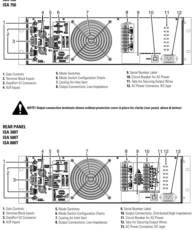
1. Gain Controls 2. Terminal Block Inputs 3. DataPort V2 Connector 4. XLR Inputs

INTRODUCTION-

REAR PANEL ILLUSTRATIONS

9. Serial Number Label

10. Circuit Breaker for AC Power 11. Tabs for Securing Output Wires 12. AC Power Connector, IEC type

REAR PANEL

ISA 280

ISA 450

ISA 750

5. Mode Switches

6. Mode Switch Configuration Charts 7. Cooling Air Inlet Vent

8. Output Connections, Low Impedance

REAR PANEL

ISA 300T

ISA 500T

ISA 800T

1. Gain Controls 2. Terminal Block Inputs 3. DataPort V2 Connector 4. XLR Inputs

5. Mode Switches

6. Mode Switch Configuration Charts 7. Cooling Air Inlet Vent

8. Output Connections, Low Impedance

9. Serial Number Label

10. Output Connections, Distributed (high impedance) 11. Circuit Breaker for AC Power

12. Tabs for Securing Output Wires 13. AC Power Connector, IEC type

5

(6)

The front panel of ISA series amplifiers is tailored for installed sound. The power switch is the only front panel control; gain controls are located on the rear panel to minimize control tampering. LED indicators are provided for power, input signal and to warn of clipping.

If the POWER LED fails to illuminate when the switch is in the ON position: The power switch is a rocker-type switch. To turn the amplifier

on, push in on the top portion of the switch. To turn the amplifier off, push in on the bottom portion of the switch.

The greenpower LED should light up when the switch is in the on position.

When the power is switched off, the LED may takes several seconds to go out; this is normal.

FEATURES & SETUP-

POWER SWITCH, COOLING AIR VENTS

Rear panel circuit breaker:

Tripped or open position; press to reset.

Rear panel circuit breaker:

Normal operating position

If the circuit breaker opens repeatedly with nothing connected to the amplifier and it is connected to the proper AC source as labeled on the rear panel serial number label, then the amplifier requires servicing.

Keep the inlet and exhaust air vents clear of any obstructions. Insure that the air exhausted from the vents has an exit from the equipment enclosure.

Equipment enclosures with insufficient air flow will cause amplifier overheating. Enclosures must allow fresh air to enter and hot air to exit.

If dust builds up, clogging the vents, use a soft brush and a vacuum cleaner to remove the dust. Use the brush to loosen the dust while the vacuum is used to pull the dust away from the amplifier.

1- Check the AC cord and insure that both ends are fully inserted into their receptacles. If the power LED still fails to illuminate,

2- Check the AC outlet for voltage with a circuit tester or known good device (lamp, etc.).

3- Check the AC circuit breaker on the rear panel of the amplifier. The illustration at the right shows the circuit breaker in its normal (operating) position and its tripped position (amplifier AC power turned off by protective circuit breaker).

COOLING AIR INLET AND EXHAUST

VENTS-NOTE! It is normal for the circuit breaker to open if the amplifier is operated continuously at output levels at or exceeding specified power levels.

(7)

SWITCH-FEATURES & SETUP-

LED INDICATORS

CLIP

:

red LED that illuminates when the amplifier clips.

Normal indication: illumination briefly at extreme output power peaks. Occasional clipping (once briefly every few seconds) when operation at high power levels is normal. At power-on, the clip LEDs may briefly flash; this is normal.

Continuous operation at high power may trigger the thermal protection circuitry, shutting down the amplifier and fully illuminating the clip LED. Operation will resume after the amplifier has cooled down sufficiently.

SIGNAL

:

green LED that lights up when the input signal is strong enough to drive the output to about -40 dB from rated 8-ohm power.

Normal indication: varying brightness corresponding to strength of input signal.

POWER

:

green LED that illuminates when the power switch is set to the on position and AC power is present at the IEC cord receptacle.

Normal indication: at power-on the LED will nate at half-brightness for 2-3 seconds, then it illumi-nates to full-brightness.

If no indication: check gain settings, input cables, connections and audio source. If audio source is extremely low signal strength,signal LED may not illuminate; this is normal but indicates that the input signal strength should be increased.

Occasional illumination: normal for weak input signal strength.

Illuminated dimly all the time with brighter flashing: normal for “average” input signal strength. Fully illuminated (on): normal for “pushing” the amplifier hard. Also, the clip indicator will probably flash dimly with the beat of the program material and brightly during extreme peaks in the material.

If no indication: see previous page for suggested items to check.

When power is switched off: the LED may take several seconds to extinguish (go out); this is normal.

If no indication: normal if the amplifier is operated at very low output levels.

Occasional illumination: Occasional clipping (once briefly every few seconds) when operation at high power levels is normal. Continuous operation at high power may trigger the thermal protection circuitry, shutting down the amplifier and fully illuminating the clip LED.

Illuminated most of the time: Not normal; reduce the output of the amplifier and/or input signal to avoid thermal shutdown of the amplifier and possible speaker damage.

Fully illuminated (on): Amplifier is in thermal shut down. Reduce gain settings or input signal and allow the amp to cool down. Leave the power on so that the fan continues to run; operation will automatically resume after the amplifier has cooled sufficiently.

(8)

FEATURES & SETUP-

GAIN CONTROLS & INPUT JACKS

GAIN

CONTROLS-The gain controls are located on the rear panel to minimize control tampering after installation. When viewing the amplifier from the rear, they are on the left end, top and bottom, as shown in the illustration to the right.

The gain controls are detented (11 steps) for repeatable adjustment. Surrounding the gain control are marks indicating

attenuation, in dB. To operate the gain control, rotate the control’s knob so that the desired level is achieved. There is a detent in the knob to indicate its position.

Maximum gain depends on the model; see chart below. MAXIMUM VOLTAGE GAIN BY MODEL

ISA 280, 300T 30.5 dB

ISA 450, 500T 33.0 dB

ISA 750, 800T 35.0 dB

The markings around the gain controls indicate attenuation from full gain. At full gain, an input signal equal to the amp's input sensitivity will produce its full rated output power. If you turn the gain down, the the same signal will produce less output power, as shown at left.

INPUTS

The ISA series of amplifiers are equipped with XLR and terminal block connectors. Input impedance is 20kW balanced, 10kW unbalanced. The proper termination and connection

information is provided in the CONNECTIONS section of this manual. Unused input connections may be used to daisy chain the input to additional amplifiers.

Additionally, a DataPort V2 connector is provided for users of QSC DataPort products. The DataPort V2 can be used to provide input signals to the amplifier and to monitor the amplifier with the appropriate QSC DataPort product. See the following section for DataPort V2 information.

TERMINAL BLOCK CONNECTORS

XLR CONNECTORS

WHERE THEY

(9)

DATAPORT V2

What It Is- The DataPort V2 is used for connection to optional QSC DataPort accessories. DataPort accessory devices can provide remote cinema monitoring, DSP, filter and crossover functions.

The “V2” DataPort connection is a “version-2” of QSC’s original DataPort. It has a reduced feature set from the original, while maintaining essential amplifier monitoring capability. It does not supply +15 VDC power required by some DataPort accessories.

FEATURES & SETUP-

DATAPORT V2

Where It Is: The DataPort V2 connector is on the rear panel, left side and center.

Using the DataPort V2 Some DataPort accessories plug directly in to the DataPort while others use an interconnect-ing QSC Dataport cable. Consult the accessory’s

documentation for recommended mounting and interconnect information.

Do not use the XLR or terminal block connections for inputs when the DataPort V2 is used as the input signal source. If you do, the signals from the DataPort V2 and regular inputs will be mixed, possibly with unexpected results.

What Can I Connect to the DataPort V2? Consult your QSC representative for up-to-date accessory compatibility. QSC has several DataPort-based accessories available like the:

DSP-3 Digital Signal Processing Module XC-3 Crossover

SF-3 Subwoofer Filter LF-3 Low Frequency Filter DCM Crossovers & Monitors (page 32 has additional information)

9

Daisy Chaining to Other Amplifiers

While Using the DataPort V2 for Input Signals: If the incoming audio input signal is through the DataPort V2, the XLR and terminal block connectors can be used to daisy chain the input signal to other equipment. The signal at these connectors will be about 10 dB lower (in voltage) than the incoming DataPort V2 signal. The illustration to the right shows the basic daisy chain hookup. Note that the XLR connections may also be used for daisy chaining the audio to other devices. Daisy chaining may not be possible with accessories that cover the XLR and/or

terminal block connectors. Daisy chaining the DataPort V2 input to other devices using the terminal block connectors.

NOTE! The DataPort V2 can only supply a maximum current of 40 mA. Some accessories, such as the DSP-3, require more than 40 mA to operate. Use an external power supply with such accessories.

(10)

FEATURES & SETUP

STEREO & PARALLEL OPERATING MODES

PARALLEL:

The channel 1 and channel 2 inputs are connected together, applying a single input signal to both channels of the amplifier. A signal into any input jack will drive both channels. Each channel's low frequency filtering, clip limiting, and gain control still function independently. Each channel drives its own speaker load.

You can patch the input signal on to additional amplifiers (daisy chain) by using any of the remaining input jacks. This feature eliminates the need for “Y” cables.

When to use PARALLEL input configuration: Use parallel mode when you need one signal to drive both channels; each channel having its own control (gain, clip limiter, low-frequency filter).

How to use PARALLEL mode:

1 Set the DIP switches for PARALLEL mode (see facing page).

2 Connect the one input signal to any one input connector.

3 Connect the two speakers: one to CH1’s output terminals, one to CH2’s output terminals.

STEREO:

Each input signal is sent to its respective channel. Each channel has independent low-frequency (subaudio) filtering, clip limiting, gain control, and output connection.

When to use STEREO input configuration: Use stereo mode for stereo sources (L-R inputs) and any other situation that requires each channel to be completely separate from the other.

How to use STEREO mode:

1 Set the DIP switches for stereo mode operation (see facing page).

2 Connect the two input signals; one to CH1 and one to CH2 (XLR or terminal blocks)

3 Connect the two speakers; one to CH1’s output terminals, one to CH2’s output terminals.

NOTE: Ensure that the MODE SWITCHES are set to STEREO when feeding two separate signals to the two channels.

STEREO MODE OPERATION

(11)

FEATURES & SETUP

STEREO & PARALLEL MODE DIP SWITCH SETTINGS

ISA 280, ISA 450, ISA 750:

Refer to the switch setting keys for each mode, to the right. These keys are printed on the amplifier’s rear panel for easy reference when you are behind the equipment rack.

SETTING THE DIP SWITCHES FOR STEREO OR PARALLEL MODE

:

“T” models

ISA 300T, ISA 500T and ISA 800T:

Refer to the switch setting keys for each mode, at the right. These keys are printed on the amplifier’s rear panel for easy reference when you are behind the equipment rack.

ISA 280, ISA 450 and ISA 750 mode switches.

ISA 300T, ISA 500T and ISA 800T mode switches.

STEREO Mode:Set switch #4, 5, 6 and #7 to the left.

PARALLEL Mode:Set switch #4 and #5 to the right; set switch #6 and #7 to the left.

STEREO Mode: Set switch #3, 4, 5, 6, 7 and 8 to the left.

PARALLEL Mode: Set switch #3, 4 and 5 to the right. Set switch #6, 7 and 8 to the left.

11

(12)

FEATURES & SETUP

BRIDGE OPERATING MODE & DIP SWITCH SETTINGS

BRIDGE MODE

OPERATION-Note that speaker connection for bridge mono mode is different than other modes. See section on Connections: Outputs for proper bridge mode output connections.

SETTING THE DIP SWITCHES FOR BRIDGE MODE

Bridge mode combines both output channels into one output. This mode is for driving a single, high-power-rated load with twice the normal voltage swing. This results in about 4 times the peak power and about three times the sustained power of a single channel. It is also common to call this bridge mono mode. When to use BRIDGE mode: Use BRIDGE mode when you need to deliver the power of two channels to a single 8 or 4 ohm load, such as a subwoofer. Do not use less than 4 ohm loads in bridge mode. Refer to the CONNECTIONS section of this manual for details.

Constant voltage drivers rated at 140 volts or 200 volts can be accommodated by bridging the high impedance output terminals of the ISA 300T, ISA 500T or ISA 800T. Refer to the CONNEC-TIONS section of this manual for details

How to use BRIDGE mode:

1 Set the DIP switches for bridge mode (see below).

2 Connect the one input signal to CH1’s input (XLR or terminal-block).

3 Connect the one speaker load to the bridge output terminals

4 Use channel 1’s gain control, clip limiter and filter.

ISA 300T, ISA 500T and ISA 800T models: switches #3, 4, 5, 6, 7 and 8 must all be set to the right-side position. Switch #10 should be set to its left-side position. See chart, above.

ISA 280, ISA 450 and ISA 750 models: switches #4, 5, 6, 7 and 8 must all be set to the right-side position. Switch #10 should be set to its left-side position. See chart, above.

ISA 280, ISA 450 and ISA 750:

1 Switch #4, 5, 6 and 7 must all be switched to the right.

2 Switch #8must be switched to the right to disable channel 2’s low-frequency filter.

3 Switch #10 should be switched to the left so that channel 2’s clip limiter is off. Channel 1’s clip limiter controls both channels in bridge mode.

4 Set switch #1, 2 and 3 as required. Channel 1’s settings determine the bridge mode clip limiting and low-frequency filtering.

ISA 300T, ISA 500T and ISA 800T:

1 Switch #3, 4, 5, 6, 7 and 8 must all be switched to the right to operate in bridge mode.

2 Switch #10 should be switched to the left so that channel 2’s clip limiter is off. Channel 1’s clip limiter controls both channels in bridge mode.

(13)

FEATURES & SETUP

LOW FREQUENCY FILTER & DIP SWITCH SETTINGS

SETTING THE FILTER DIP SWITCHES

1 Set switch #3 and #8 to the on or off position as desired. 2 Select the desired roll-off frequency at switch #2 and #9. 3 If filter off is selected, the frequency selection has no effect. If operating in BRIDGE MODE

1 When in bridge mode, channel 2’s low frequency filter and clip limiter should be switched off.

2 Channel 1’s filter settings (and clip limiter) determine amplifier behavior. Set channel 1’s low frequency filter on-off switch, frequency selection switch and clip limiter as desired.

ISA 280, ISA 450 and ISA 750 models: frequency selection is 30 and 70 Hz. Low frequency filter can be switched on or off with switches #3 and #8.

Generally, match the frequency selection to your speaker’s low frequency capability. This improves speaker performance by limiting subaudio cone movement, making more power available for the speaker’s rated frequency range. Unless you already have filtering in the signal path preceeding the amplifier, use the low frequency filter to protect your speakers from cone over-excursion caused by frequencies below the speaker’s limits. The speaker’s documentation will specify the low frequency limit.

ISA 280, ISA 450 and ISA 750‘s have defeatable low frequency filters with selectable roll-off frequencies of 30 and 70 hertz. Each channel has its own low frequency filter which can be enabled or defeated using thefilter on-off switch. The frequency is determined by the frequency selection DIP switch. There is a 5 hertz roll-off in the filter off position to protect the speaker loads from sub-audio or DC signals. The off position should be used only for subwoofer systems with rated frequency response below 30 hertz or if low frequency filtering is provided by other devices.

ISA 300T, ISA 500T and ISA 800T’shave selectable roll-off frequencies of 50 and 75 hertz. The frequency is determined by the frequency selection DIP switch. The low frequency filter is always active and is not defeatable. This is required by the presence of magnetic devices (coupling transformers) in constant voltage distributed audio systems. The low impedance outputs of these models have the same low frequency roll-off as the autotransformer coupled high impedance outputs.

ISA 300T, ISA 500T and ISA 800T:

If operating in STEREO or PARALLEL MODE

1 Select the desired roll-off frequency (50 or 75 Hz) at switch #2 and #9. Each channel can be set independently.

If operating in BRIDGE MODE

1 Select the desired roll-off frequency at switch #2. Setting of switch #9 is ignored.

To Prevent Output Transformer Saturation

The 50 Hz filter setting prevents transformer saturation for normal, unclipped program levels. If heavy clipping is possible, use the 75 Hz setting for extra protection. See “Low Frequency Filtering for 70–100V Systems,” page 28.

Differences Between “T” & “non-T” Models:

ISA 300T, ISA 500T and ISA 800T models: frequency selection is 50 and 75 Hz. Low frequency filter is always active and can not be defeated (turned off).

ISA 280, ISA 450 and ISA 750:

If operating in STEREO or PARALLEL MODE

(14)

FEATURES & SETUP

FREQUENCY RESPONSE CURVES

Frequency response curve for:

ISA 300T

ISA 500T

ISA 800T

Note! There is no “Filter OFF” selection on “T” models.

Frequency response curve for:

ISA 280

ISA 450

ISA 750

50 hertz selection 75 hertz selection

Filter ON 70 hertz selection

Filter ON 30 hertz selection

(15)

FEATURES & SETUP

CLIP LIMITER & DIP SWITCH SETTINGS

CAUTION: Clip limiting reduces extreme overdrive peaks, allowing a higher average signal level without audible distortion. However, increasing the gain with the clip limiter engaged, until clipping is again audible, can double the average output power. Be careful not to exceed the power rating of your speakers.

How to use it: When to use it:

When the audio input signal drives the amplifier’s output circuit beyond its power capability, the amplifier clips and flattens the peaks of the waveform. This flattening is what we hear as distortion during the clipping.

Clipping for short periods can be harmless. Clipping for extended periods can easily damage high frequency drivers (tweeters, horns) . Low frequency drivers can tolerate all but severe clipping; severe clipping can damage any of the systems power components and should be avoided entirely.

The clip limiter detects clipping (even short events) and quickly reduces the gain to minimize the amount of overdrive. To preserve as much of the program dynamics as possible, the ISA amplifier has limiters which respond only to amplifier clipping. There is a switchable clip limiter provided for each channel.

CLIP LIMITER selection switches, all models. Note! In BRIDGE mode, channel 2’s CLIP LIMITER must be placed in the OFF position for proper operation.

In BRIDGE mode, Channel 2’s clip limiter must be set to the off position to avoid any interaction. We recommend using the clip limiters in all applications.

When driving full-range speakers, clip limiting reduces high frequency distortion caused by bass overload. It also protects high frequency drivers from excess overdrive and harsh clipping harmonics.

When using 70V or 100V transformers, clip limiting prevents excessive overdrive which could saturate the coupling transformers. See “Low Frequency Filtering For 70–100V Systems” on page 28.

If operating in stereo or parallel mode, the two limiters are completely independent of one another.

1 Set each channel’s clip limiter selection switch on or off as desired. Switch #1 sets channel 1’s limiter. Switch #10 sets channel 2’s limiter.

If operating in bridge mode, channel 1’s clip limiter switch is used to engage or disable the clip limiter; channel 2’s clip limiter must be switched off.

1 Set channel 2’s clip limiter switch to the off position. This is switch #10. 2 Set channel 1’s clip limiter switch on or off as desired. This is switch #1.

(16)

INSTALLATION:

RACK MOUNTING AND MOUNTING DIMENSIONS

Securing the front ears to the rack rails Use four screws and washers when mounting the ISA amplifier to the front rails. Support the weight of the amplifier while securing it to the rails to avoid bending or distorting the front rack mount ears.

ISA Rack Mounting

Method 2: The amplifier is first installed from the front of the rack. Then, the accessory rear ears are positioned on the rear rack rails and secured. The pin installation position can now be selected. Install the pin so that it fits well into the slot provided on the amplifier's rear mounting tab.

Method 1: The amplifier is first installed from the front of the rack and then the ears are secured directly to the amplifier with two machine screws as shown, left. Then the ears are secured to the rails using ordinary rail hardware. Supporting the rear of the amplifier

Supporting the amplifier at the rear is extremely important, especially for mobile and portable use. Equipment is often installed in racks at a remote location, then later transported to the installation site. During transport, the shock loads encoun-tered on the chassis and rack can easily damage an unsupported amplifier and the rack rails. Unless the amplifier is being installed in its final, fixed location, we strongly recommend supporting the rear of the amplifier.

Rear rack mounting ear kits are an accessory item and are available from QSC’s Technical Services Department or from your dealer or distributor. The rear rack mounting ear kit may be installed in two different ways. Refer to the literature included with the rack mounting ear kit for up-to-date information. The basic information is supplied here to give you an idea of how the accessory rack mounting ears are used.

Amplifiers are inherently heavy. It is highly recommended that you have an assistant support the amplifier during rack installation to avoid injury.

(17)

INSTALLATION:

COOLING REQUIREMENTS & AC MAINS

FAN COOLING

Keep the front and rear vents clear to allow full air flow. Make sure that plenty of cool air can enter the rack, especially if there are other units which exhaust hot air into it.

Connecting to the wrong line voltage is dangerous and may damage the amplifier or constitute the risk of electric shock. Verify the correct AC line voltage by checking the specification printed on the serial number sticker on the rear panel.

OPERATING VOLTAGE (AC mains)

Air flow in QSC amplifiers All QSC amplifiers draw cool air into the rear of the amplifier and

exhaust the hot air from the front. This is done so that the equipment in the rack stays as cool as possible. This method of cooling also gives the technician “direct” air temperature feedback at the front of the rack, where it is the most conve-nient. The front panel’s temperature is an accurate indicator of “how hard” the amplifier is working.

The fan varies speed automatically to maintain safe internal temperatures and minimize noise. Keep the front and rear vents clear to allow full air flow.

Hot air exhausts out the front of the amp so it does not heat the interior of the rack. Make sure that plenty of cool air can enter the rear of the rack, especially if there are other units which exhaust hot air into it. Also ensure that the exhaust air from the front of the amplifier is not obstructed by an equipment cabinet door (or otherwise).

Connect the AC line cord after the amplifier has been installed in the equipment rack. The IEC plug (the rectangular “block” plug-end of the AC power cord) can only be inserted when it is properly oriented with the IEC receptacle on the rear panel of the amplifier. Orient the IEC plug correctly and push the plug firmly into the IEC receptacle; it should seat tightly.

The correct AC line voltage is shown on the serial number label. Connecting to the wrong line voltage is dangerous and may damage the amplifier.

The AC line cord attaches to the IEC connector on the rear panel. Use the cord supplied with the amplifier, or an equivalent. Insure that the wire gauge of the cord is #14AWG. Use of #16 or #18 AWG can be dangerous and is not recommended. The larger AWG number indicates a physically smaller wire; smaller AWG number indicates a physically larger wire (#12 AWG is able to carry more current than #14AWG).

Use the best possible connection to the AC power source. Avoid extension cords as they will cause some voltage drop between the AC source and you amplifier. If the use of an extension cord is required, ensure that it is the shortest length possible and is at least #14 AWG. Smaller AWG number means larger wire size (example: #12 AWG is a larger physical wire size than #14 and able to carry more current). Ensure that all grounding connections are maintained.

17

(18)

Unbalanced inputs: Connect the conductors to the connector as shown. Make sure that the unused side of the balanced input is connected to ground, as shown.

XLR: unbalanced connection Terminal block: unbalanced connections

XLR : balanced connection Terminal block: balanced connections

CONNECTIONS:

INPUTS

XLR & TERMINAL BLOCK

jumper shield

Terminal Block Connectors: XLR Connectors:

Each channel has active balanced "Euro-style" terminal block and XLR input jacks wired in parallel. The input impedance is 20kW balanced or 10 kWunbalanced. Unused input jacks may be daisy chained to additional amplifiers.

Balanced connection is recommended. Balanced signals are less prone to AC hum and other electrical noise. Unbalanced signals can be suitable for short cable runs. The signal source's output impedance should be less than 600 ohms to avoid high fre-quency loss in long cables.

If the DataPort V2 is being used for the input signal source, the XLR and terminal block connections should not be used for inputs. However, they may be used for daisy chaining the DataPort V2 input signal to other amplifiers. The signal available from the XLR and terminal block connections will be about 10 dB lower than the DataPort V2 signal.

shield

TERMINAL BLOCK CONNECTORS

XLR CONNECTORS

Balanced inputs: Connect the conductors to the connector as shown.

(19)

CONNECTIONS:

INPUTS

DATAPORT V2

The ISA series of amplifiers come with a DataPort V2 connector that may be used for connecting to accessory QSC DataPort devices. The V2 (or version 2) DataPort does not have the full capability of the standard DataPort. The DataPort V2 must be connected to a QSC DataPort product with a QSC DataPort cable; similar looking computer data cables will not work and could damage your QSC equipment. The DataPort V2 connection will supply the input signals to the amplifier. If using the DataPort V2 connection, do not apply inputs to the XLR or terminal block connectors.

If the ISA amplifier is being used in a system monitored through a QSC cinema monitor (or other QSC DataPort product) the following amplifier information will be provided by the amplifier DataPort V2:

CH1 and CH2 output voltage Amplifier AC power status (on or off)

If using the DataPort V2 connection, do not connect any inputs to the XLR or terminal block connectors. The unused XLR or terminal block inputs may be used for daisy -chaining the DataPort V2 input signal to other amplifiers. The signal level available from the unused inputs will be about 10 dB lower than the signal applied at the DataPort V2 connector.

How to Connect to the DataPort V2:

Basic Operation Notes:

1 For operation, set the amplifier gain controls to the highest settingsyou will need. However, use reduced

gain settings during setup and test.

2 Use the DataPort accessory device to which the amp is connected to control audio levels.

3 The amplifier’s AC power cannot be controlled via the DataPort V2. Use the amplifier’s power switch to turn the amp on and off.

4 See page 32 for additional DataPort V2 application information.

If it is an accessory that mounts directly to the rear of the amplifier, orient the accessory correctly and attach to the amplifier per the accessory’s instructions.

If the accessory attaches with a QSC DataPort cable, orient the HD-15 male plug correctly with the DataPort V2 socket on the amplifier (it is “D” shaped and will fit only one way). Push the plug onto the socket firmly and ensure it is seated properly. Finger-tighten the 2 retaining screws. Do not over-tighten.

(20)

CONNECTIONS:

OUTPUTS

USING THE SCREW TERMINAL CONNECTIONS

GENERAL

The screw terminal output connections are protected by a hinged plastic cover.

To make connections to the screw terminals, you will need to swing the cover door open. Gently pry the cover with your fingertips on the side that has the wire openings.

After the door is open, loosen the screws for the terminals you are planning to use. Do this by rotating the screw counter-clockwise with an appropriate screwdriver.

After loosening the screws, slide the tongue terminals under the head of the screw and seat the terminal firmly against the screw. Tighten the screw by rotating it clockwise with an appropriate screwdriver.

Alternately, wire connections may be made. Ensure that all wires are neatly terminated with no loose strands. Do not strip the insulation back excessively. Loose strands and exposed wire beyond the terminals may cause a short circuit and cause protective muting of the amplifier.

Once all connections have been made, close the protective cover by swinging it over the connections and pressing it toward the amplifier. If you wiring job is messy, you may need to loosen and reposition some cables to get a good fit for the cover.

1) Protective cover closed, covering the screw terminals. 2) Protective cover in the open position.

3) Tongue terminals being inserted under loosened screws. Tighten all connec-tions before closing cover.

4) Protective cover shown closed over exiting cables.

The tongue terminals should have an overall width (of the tongue) no larger than 0.320 inch. The opening for the screw should be no smaller than 0.135 inch. The wire insertion barrel should be sized for the size of speaker cable used.

#6 is the screw size used on the ISA output terminals; this is also the size that tongue terminal suppliers may use in their nomenclature.

STACKING OF TONGUE TERMINALS

If you need to fit two tongue terminals onto one screw, they should be oriented properly for a good fit and reliable connection. Refer to the diagram below. Place the flat sides of the two terminals toward one another, then tighten screw. If oriented incorrectly, the terminals will bend and possibly not connect very well. The screw terminal may also be damaged.

(21)

CONNECTIONS:

OUTPUTS

DIRECT LOW IMPEDANCE (LO-Z)

BRIDGE MODE PRECAUTIONS:

Do Not Use 2-ohm loads in Bridge Mono Mode! 4 ohms is the minimum impedance for bridge mono operation! This mode puts a high demand on the amplifier and speaker. Excessive clipping may cause protective muting or speaker damage. Ensure the speaker has a sufficient power rating.

Output voltages greater than 100 volts rms are available between the amplifier's bridged terminals. CLASS 2 or CLASS 1 wiring methods, as specified in accordance with national (NEC) and local codes, must be used to connect the speaker. To prevent electric shock, do not operate the amplifier with any conductors of the speaker cable exposed. Consult the local & national electrical codes for full information.

ISA amplifiers are equipped with screw-terminal output connections. The ISA 280, ISA 450 and ISA 750 provide low-impedance outputs only (2 to 16 ohms) while the ISA 300T, ISA 500T and ISA 800T provide both low-impedance and high-impedance (25V, 70V and 100V) outputs.

When selecting speaker cable (wire), always use the largest wire size and shortest length of wire practical for any given installation. Larger wire sizes and shorter lengths minimize power loss and degradation of damping factor. Do not place speaker cables next to input wiring.

Direct Low Impedance Output Connections

:

Use these terminals for 2 through 16 ohm loads.

STEREO or PARALLEL Mode: Connect each speaker cable to its respective channel’s screw terminals. Make sure speaker polarity is maintained. Note that channel 1 and channel 2 connections have the positive (+) terminal in different locations.

BRIDGE Mode: Connect the one speaker cable to the center screw terminals labeled BRIDGE MONO. Make sure speaker polarity is maintained. 2 ohm loads are not usable in BRIDGE mode.

(22)

CONNECTIONS:

OUTPUTS

DISTRIBUTED HIGH IMPEDANCE (HI-Z) , STEREO & PARALLEL

Stereo and Parallel Amplifier Mode Distributed Output Connections

Use these terminals for 25, 70 or 100 volt distributed loads when the amplifier is in stereo or parallel mode.

The ISA 300T, ISA 500T and ISA 800T amplifiers have high impedance (Hi-Z) outputs suitable for driving 25, 70, and 100 volt distributed audio lines. These loads should be driven by the amplifier in stereo or parallel modes. For 140 volt or 200 volt output, the amplifier must be configured for bridge mode. Bridge mode connections to the high impedance distributed outputs is discussed on the following page. In the diagrams below, only one speaker load for each channel is shown for clarity. Distributed lines usually have several speaker loads on each output line.

Class 2 wiring may be used. For bridged mono and 100V distributed outputs, class 1 wiring must be used. 25 Volt Stereo or Parallel Connection

70 Volt Stereo or Parallel Connection

100 Volt Stereo or Parallel Connection

70 volt lines:

Connect one of the 70 volt lines to the CH1 terminals marked 70V.

Connect the other 70 volt line to the CH2 terminals marked 70V.

The 70V connection is between the 0 and 70

markings.

Ensure proper polarity is maintained for all connections.

25 volt lines:

Connect one of the 25 volt lines to the CH1 terminals marked 25V.

Connect the other 25 volt line to the CH2 terminals marked 25V.

The 25V connection is between the 70 and 100

markings.

Ensure proper polarity is maintained for all connections.

100 volt lines:

Connect one of the 100 volt lines to the CH1 terminals marked 100V.

Connect the other 100 volt line to the CH2 terminals marked 100V.

The 100V connection is between the 0 and 100

markings.

Ensure proper polarity is maintained for all connections.

OUTPUT TERMINAL SAFETY WARNING!

Do not touch output terminals while amplifier power is on. Make all connections with amplifier turned off. Risk of hazardous energy!

(23)

CONNECTIONS:

OUTPUTS

DISTRIBUTED HIGH IMPEDANCE (HI-Z) , BRIDGE MODE

OUTPUT TERMINAL SAFETY WARNING!

Do not touch output terminals while amplifier power is on. Make all connections with amplifier turned off. Risk of hazardous energy!

BRIDGE mode operation combines the output power of both channels into one channel that has twice the normal voltage swing. This means that in BRIDGE mode, the high impedance distributed outputs can provide 140 volt (70 volt + 70 volt) and 200 volt (100 volt + 100 volt) drive. There are not many drivers (speaker loads) that operate at 140 or 200 volts, but if required, the ISA “T” models can easily be configured to fit the application.

140 and 200 volt bridging may be useful for installations where two 70-volt or two 100-volt drivers are connected in series. An example of each of these situations is provided, below. Consult local and national electrical codes to ensure that proper wiring materials and methods are used.

BRIDGE CONNECTION TO DISTRIBUTED OUTPUTS

200 Volt Bridge Connection 140 Volt Bridge Connection

200 volt line:

Connect the 200 volt line between the CH1 100

terminal and the CH2 100 terminal.

Note that the positive (+) terminal is connected to channel 1’s 100 volt terminal and the negative terminal is connected to channel 2’s 100 volt terminal.

Ensure proper polarity at all connections.

Note polarity of connection between the two drivers in series.

140 volt line:

Connect the 140 volt line between the CH1 70

terminal and the CH2 70 terminal.

Note that the positive (+) terminal is connected to channel 1’s 70 volt terminal and the negative terminal is connected to channel 2’s 70 volt terminal.

Ensure proper polarity at all connections.

Note polarity of connection between the two drivers in series.

NOTE: When the MODE SWITCHES are set to BRIDGE mode, all output connections are configured for bridge mono operation. All output connections (low impedance direct AND high impedance distributed) must be made bridged.

23

(24)

CONNECTIONS:

POWER SHARING BETWEEN HIGH & LOW IMPEDANCE OUTPUTS

The ISA 300T, ISA 500T and ISA 800T models are equipped with autotransformer-coupled, high impedance (High-Z) outputs. They are also equipped with low impedance (Low-Z) “direct” outputs. The high impedance outputs are not isolated.

The unique feature of the “T” model outputs is that you can connect loads to the high impedance AND low impedance outputs for maximum system flexibility. If the total output power of a channel’s high impedance connections does not exceed 20% of maximum rated power, then any of the rated low impedance load values can be connected at the low impedance terminals. For applications where the high impedance output power is 20–50% of maximum, then 8- or

16-ohm loads on the low impedance output areokay. If the

high-impedance output power is 50 to 80% of rated power,

then 16-ohm loads are okay. If the total output of a channel’s

high-impedance connections exceeds 80% of that channel’s maximum rated power, then DO NOT USE the low imped-ance outputs. The following chart is a useful guideline:

Power sharing between “Direct” (Lo-Z) and “Distributed” (Hi-Z) Outputs: Acceptable Low-Z loads as a function of High-Z output power. NOTE! “Caution” advisory means that this load impedance may be suitable for low power or low duty cycle applications.

(25)

CONNECTIONS:

SECURING OUTPUT WIRING TO CHASSIS

Part of any quality sound system installation is ensuring that your connections remain tight and reliable over time. Making high quality terminations to the screw terminals is one part of that reliability equation. Keeping those terminations from moving is the other part. If the connections are prevented from stress and strain, they should remain reliable.

All ISA amplifiers have integral wiring tie-down points stamped into the steel chassis. When used properly, they will help keep your connections reliable. Securing the wires to the tie-down tabs will keep the stress of wire movement and “inadvertent” pulling off the connections. These tie-down points are located on the rear panel, right side, above the IEC power connector.

After all connections have been made and verified, carefully “dress” the wires into neat lines straight form the connection and across the tie-down tab. Working from one end to the other, secure each lead (or group of leads) to its respective tie-down tab. Continue until all wires have been secured.

(26)

OPERATION:

AC POWER SWITCH, LED INDICATORS, GAIN CONTROLS

NORMAL OPERATING LEVELS

The amplifier’s protective muting system guards against excessive internal temperatures. With normal ventilation and 4 -to 8-ohm loads, the amplifier will handle any signal level, including overdrive. Lower load impedances and higher signal levels produce more internal heating. When using 2-ohm loads, frequent or prolonged clipping may trigger thermal shutdown.

AC POWER SWITCH

Before applying power, check all connections and turn down the gain controls. When the AC power is switched on, the power indicator LED will light at half brightness and the fan will start. The outputs are muted. Then the power indicator fully

illuminates and the amplifier unmutes. The clip and signal LEDs will flash briefly. When the clip LEDs go out, the amplifier is ready.

After the amplifier has been powered up, slowly increase the Gain settings for each channel and check for the proper operation of all speaker loads. If you detect any problems with speakers or wiring, turn the amplifier off, correct the problem and try again. Once the system has been tested, adjust Gain levels as required.

FRONT PANEL LED INDICATORS

At full brightness, the green powerLED indicates that the amplifier is operating. Half brightness indicates the amp is in its muting mode.

As the input signal strength increases, the green signalLED indicators will illuminate.

The red clipLED indicator flashes during overload (clipping). A bright, steady glow indicates protective muting; if this occurs during use, see Troubleshooting.

NOTE! Page 7 contains detailed descriptions of the LEDs and how to interpret their indications.

A NOTE ON SOUND PRESSURE LEVELS:The ear converts vibration from sound waves into impulses in the nerves of the inner ear. Sound levels above 90 decibels, particularly if prolonged, may cause

vibration intense enough to damage the inner ear.A large truck about

five feet away is about 90 decibels loud. A jackhammer emits sound

levels of about 120 dB at three feet away, and a jet engine is

about 130 dB from 100 feet away. Motorcycles, snowmobiles, and similar engines range around 85 to 90 dB, and a rock concert may exceed 100 dB. A general rule of thumb is that if you need to shout to be heard, the sound

level is high enough to damage hearing.

Some jobs in the entertainment industry involving loud noise from music carry high risk for hearing loss. In the U.S., on-the-job noise exposure is regulated by law. Both the length and the intensity (sound level) of

noise exposure are considered. If exposure reaches or exceeds the

levels listed at right, protective measures must be taken. The table is referenced from OSHA’s Permissible Noise Exposure table G16.

The power switch is a rocker-type switch. To turn the amplifier on, push in on the top portion of the switch. To turn the amplifier off, push in on the bottom portion of the switch. The green power LED should illuminate when the switch is in the on position. The LED may takes several seconds to extinguish when the power is switched off, this is normal.

GAIN CONTROLS

The gain controls are located on the rear panel of the amplifier as shown on page 6. The controls are detented (11 steps) for repeatable adjustment. Surrounding the knob are markings indicating the amount of attenuation in dB. To operate the gain control, rotate its knob to reach the desired sound level. There is a detent in the knob to indicate its position.

(27)

APPLICATIONS:

GENERAL APPLICATION INFORMATION

The ISA 280, ISA 450 and ISA 750 amplifiers are optimized for directly driving low impedance loads. Low impedance (Lo-Z) loads are those loads between 2 and 16 ohms. These models are not suitable for driving “constant voltage” 70V lines. These low impedance models are referred to collectively as the “non-T” models. The Lo-Z outputs will handle impedances down to 2 ohms. Loads of 2 ohms demand substantially higher output currents from the amplifier and should be used with some caution. If operated at reasonable power levels (similar to 1/8 rated power with pink noise test signal) with 2-ohm loads, the amplifier will perform exceptionally. At high power with chest-pounding bass program material, excessive clipping with 2-ohm loads may cause excessive heat in the amplifier and trigger thermal shutdown.

The ISA 300T, ISA 500T and ISA 800T amplifiers have the additional capability of driving constant voltage distributed audio lines of 25, 70 and 100 volts. The outputs are autotransformer coupled; they are not fully isolated. These autotransformer equipped models also have low impedance outputs for added flexibility of system design and configuration. The total available output power from each channel can be shared between the direct low impedance outputs and the autotransformer coupled high impedance outputs. These high impedance capability models are referred to collectively as the “T” models.

General ISA Application Information

Distributed Line Principles (“T” models only)

Distributed lines are the easiest and most reliable way of distributing audio to many low-power speaker loads located over a wide area. It is easy to use because all the loads are connected in parallel across a pair of wires; there is normally no need to put speakers in series or series-parallel arrangements to meet specific impedance requirements. It is reliable because the parallel connection scheme makes it so that if any one speaker fails, the remaining speakers will continue to operate. Additionally, since the operating voltage of distributed lines is fairly high, the current through the line is kept fairly small; this minimizes resistive losses in the wiring. Distributed line systems are usually referred to by their nominal operating voltage with 25, 70 and 100 volt systems being the most common. The main difference with the various operating voltages will be the type of matching transformer on the speaker assembly. In the illustration below, the 70-volt transformer is connected to the 70-volt output terminals of channel 2 of the amplifier. The input to the transformer may be connected to different taps that determine the nominal power that will be delivered to the speaker. The example shows taps available for 2.5, 5, 10 and 20 watts;the 10-watt tap is used. Some transformers also can match the distributed line to several common speaker impedances; make sure that the speaker is connected to the appropriate tap. In North America, 70-volt systems are most common, while 100-volt systems are more common in Europe. Usually, 25-volt systems are found in older commercial intercom-type components being maintained with new amplifiers.

The example below shows a 70-volt line with one speaker load attached, but most distributed lines will have many speakers connected

in parallel. To estimate the power requirements for a line, simply add all the power requirments of its speakers. In the example, the

transformer is set for 10 watts. If the line had nine more speakers configured the same way, the sum of their power requirements would

be 100 watts. The same technique applies to 25- or 100-volt systems too,although the speaker transformer would have to be rated and marked accordingly, and the amplifier connections would have to be at the appropriate 25V or 100V output terminals.

(28)

APPLICATIONS:

LOW FREQUENCY FILTERING & DISTRIBUTED OUTPUTS

The low frequency filtering is another difference in the characteristics of the “non-T” and the “T” amplifiers. Because transformers and other magnetic devices are prone to low frequency saturation, the low-frequency response autotransformer-equipped “T” models is limited. The default low frequency roll-off is at 50 Hz; 75 Hz is the other available selection. Low frequencyfiltering is

always active on the “T” models. This low frequency roll-off is required primarily to protect the smaller matching transformers on the speakers of constant voltage distributed audio systems, but also aids in minimizing low frequency distortion of the system in general.

The varying degree of quality of coupling transformers may require the roll-off frequency to be set to the higher 75 Hz selection. The change from 50 to 75 Hz may seem minor, but in terms of low frequency drive, it reduces the required magnetic flux in the

coupling transformers by about 30%. If the application requires driving speaker loads at or near their rated power, or with program material that’s heavy on the bass, a marked performance increase may be realized with the 75 Hz low frequency roll-off. A careful system listening evaluation will aid in the best selection for any application.

The low frequency filter is not a “brick wall,” and if the amplifier is overdriven, it may defeat the benefits of the filter to some extent. Normally, such signal levels will cause the amplifier to clip, which is the first sign of potential danger. Midband clipping puts no unusual strain on the transformers, but full-range material with heavy clipping will probably overdrive the 70–100V transform-ers to saturation, even with the 50 Hz filter. This will cause an additional layer of “hash” in the clipping, and will also result in audible clicking noises from the transformers inside the amplifier. These symptoms indicate abnormal stress and should be avoided for maximum service life. If unpredictable clipping is possible, use the Clip Limiter to prevent long-term overloads and use the 75 Hz filter position for extra protection. The clip limiter will not affect performance when no clipping is present, and therefore is recommended as the default setting. The 50 Hz filter is suitable for program material which remains within the amplifier’s normal headroom and will provide slightly better bass on wide-band speakers.

If a system with sub-woofers is desired, we recommend the use of the low-impedance ISA 280, ISA 450 or ISA 750 with low-imped-ance sub-woofer drivers. The low frequency performlow-imped-ance of the directly-coupled system is superior to the magnetically-coupled systems. Remember that all of the outputs on the “T” models are low frequency limited to 50 Hz by default. For all applications requiring audio performance below 50 Hz, use the low impedance, “non-T” models with low impedance speakers.

Low Frequency Filtering for 70-100V Systems

25 Volt, two-zone example:

The illustration to the right shows a typical two-zone 25-volt system. When using 25 volt speaker loads, make sure that connections to the amplifier are made to the 25 volt output terminals.

If using the ISA 300T, 300 watts per channel (zone) can be delivered. Make sure that the total speaker power load on each channel does not exceed 300 watts.

If using the ISA 500T or ISA 800T, the per-channel power capability is 550 and 800 watts, respectively.

Distributed Output Application Examples

Class 2 wiring may be used. For bridged mono and 100V distributed outputs, class 1 wiring must be used.

OUTPUT TERMINAL SAFETY WARNING!

Do not touch output terminals while amplifier power is on. Make all connections with amplifier turned off. Risk of hazardous energy!

(29)

100 Volt, two-zone example: The illustration to the right shows a typical two-zone 100 volt system. When using 100 -volt speaker loads, make sure that connec-tions to the amplifier are made to the 100 volt output terminals.

If using the ISA 300T, 300 watts per channel (zone) can be delivered. Make sure that the total speaker power load on each channel does not exceed 300 watts.

If using the ISA 500T or ISA 800T, the per-channel power capability is 550 and 800 watts, respectively.

Bridge Mode Using Hi-Z Outputs

Bridging of the Hi-Z outputs is possible with the “T” models; see page 22.

29

APPLICATIONS:

DISTRIBUTED OUTPUTS

70 Volt, two-zone example:

The illustration to the right shows a typical two-zone 70-volt system. When using 70-volt speaker loads, make sure that connections to the amplifier are made to the 70-volt output terminals.

If using the ISA 300T, 300 watts per channel (zone) can be delivered. Make sure that the total speaker power load on each channel does not exceed 300 watts.

If using the ISA 500T or ISA 800T, the per-channel power capability is 550 and 800 watts, respectively.

OUTPUT TERMINAL SAFETY WARNING!

Do not touch output terminals while amplifier power is on. Make all connections with amplifier turned off. Risk of hazardous energy!

Class 2 wiring may be used. For bridged mono and 100V distributed outputs, class 1 wiring must be used.

(30)

APPLICATIONS:

MULTIPLE LOW IMPEDANCE LOADS IN SERIES (all models)

Series connection is where the same signal current flows through each of the speaker loads. The signal goes into one terminal of the first speaker and out its other terminal; then the signal goes into one terminal of the next load, and so on. If any of the speakers in a series-connected branch of a system fails, the signal is prevented from flowing through any of the loads (no sound). Total impedance for series connections is the sum of each of the impedances in the chain (see illustration, below). Series connection schemes are usually used with “raw” speakers (not often with speaker cabinets) for wiring conve-nience. The exposed speaker connections make this method easy for small strings of speakers in one area. Most PA-type Multiple Lo-Z Loads in Series:

speaker cabinets are not wired for series connection ability; consult your speaker’s documentation for connection information. It is not recommended to connect speakers of different imped-ances in series because power will be divided unequally between them. If you are experienced with mixing and matching speaker loads of varying impedances, no damage to the amplifier will result as long as the total impedance is within 2 to 16 ohms per channel.

Below are examples of series connections for 2-, 4- and 8-ohm speaker loads. Connecting 16-ohm speakers in series will seriously

(31)

APPLICATIONS:

MULTIPLE LOW IMPEDANCE LOADS IN PARALLEL (all models)

If each speaker load is connected across the same signal source (the output of the amplifier), then the loads are in parallel with one another. If one of the speakers fails in a parallel-connected system branch, the remaining speakers will continue to operate. If all speaker loads are the same impedance, the total imped-ance of a parallel-connected system branch is the impedimped-ance of one speaker load divided by the number of loads in the branch (example: three 8-ohm loads in parallel: 8/3=2.667 or roughly 2.7 ohms).

It is not recommended to connect speakers of different imped-ances in parallel because power will be divided unequally between them. If you are experienced with mixing and matching speaker loads of varying impedances, no damage to the amplifier will result as long as the total impedance is within 2 to 16 ohms per channel.

Most PA-type speaker cabinets are provided with two or more input jacks that are wired in parallel. If one cabinet is connected to the amplifier, the load impedance is equal to the one cabinet’s specified impedance. If you attach another similar cabinet to the remaining jack of the first cabinet, the two cabinets are now in parallel with each other and the impedance will be half of the one-cabinet value. Consult your speaker’s documentation for connection details as there are many connection methods in use. Below are examples of parallel connections of 4-, 8- and 16-ohm speakers. Do not use parallel 2-ohm loads, because the result will be 1 ohm or less; this is too low an impedance for almost any amplifier.

Multiple Lo-Z Loads in Parallel:

(32)

The DSP-3 Digital Signal Processing Module provides compressor-limiter, multiple parametric filters, high- and low-pass filters, shelf filters, multiple delays, polarity reversal, muting and attenuation. These features and more come packed into a small module that interfaces with the DataPort V2 connector on the rear of your ISA amplifier. Not all features of the DSP-3 are available via the “Version 2” DataPort; consult your QSC sales professional for full details. The accessory remote power supply must be used to supply DC power to the DSP-3; accessory module power is NOT provided by the ISA amplifiers.

The XC-3 Crossover provides a built-in active two-way crossover. It features fourth-order Linkwitz-Riley filters with SIP selectable crossover frequencies, DIP-switch control of high-frequency equalization for CD horn equalization, SIP selectable subsonic filter, and SIP selectable all-pass low-frequency delay.

The SF-3 Subwoofer Filter is used primarily as an adjustable bandpass filter for subwoofers. The filter may be configured for a flat roll-off or a boosted response to equalize certain subwoofer models with step-down tuning. The use of a subsonic filter at the vented box tuning frequency protects speakers from damage and prevents the waste of amplifier power on excessive and inaudible low-frequency noise.

The LF-3 Low Frequency Filter is a new module for tri-amp applications. The LF-3 provides low-frequency bandpass filters for each amp channel and is used in conjunction with XC-3’s to power a tri-amp system. The XC-3 provides mid and high-pass functions for each speaker system.

The DCM Crossover & Monitors will work with the ISA amplifiers. The “AMP TYPE” selection in software must be set to UN-KNOWN. This will disable the load fault detection and AC power control as these features are not supported by the ISA series. Consult your QSC applications engineer regarding integration of ISA amplifiers with DCM products.

The CM16a Amplifier Network Monitor will not work with the ISA series of amplifiers.

APPLICATIONS:

DataPort V2 (all models)

Below are listed the available QSC DataPort-compatible products that will interface with your ISA amplifier. This list will continuously change as new products become available and old products are discontinued. Always use a QSC DataPort cable for remote equipment interconnect. Computer data cables, although similar in appearance, will not function properly and may damage your equipment. Contact your QSC dealer for details and for QSC accessories. This listing is current at time of writing, for up-to-date accessory information, contact your QSC representative.

Always use a QSC DataPort cable for remote equipment interconnect. Computer data cables, although similar in appearance, will not function properly and may damage your equipment.

Figure

12. Tabs for Securing Output Wires 13. AC Power Connector, IEC type

References

Related documents

a) Public tree pruning conducted by ISA Certified Arborists shall be in accordance with the standards and requirements of the ISA as published in the ISA Arborists

Most Market Funds will be managed by a fund manager, usually outside Alico, who will charge an Annual Management Charge (AMC) which is reflected in the values of the assets within

Merlin, in partnership with the National Society for Earthquake Technology (NSET) have conducted structural and non-structural assessments of 3 hospitals and 2

To be a True Aurovilian The Galaxy Concept of the City Matrimandir ­ Soul of the City Founder: The Mother Visionary: Sri Aurobindo Words of Wisdom

The organization and giving habits of the Colombian diaspora can be classified in seven major categories: (1) individual direct contributions to support a cause in a community or

Objectives— The aim of this study was to determine if early gadolinium enhancement (EGE) by cardiovascular magnetic resonance (CMR) imaging in a canine model of reperfused myocardial

Patient History 21 Maladaptive Behaviors 21 Reading Dysfunction 21 Saccadic Eye Movements 22 Saccadic Suppression 23 Objective Testing 23 Southern California College

As noted previously, early on pension funds did not hold many foreign assets, given that the policy mix of an exchange rate band and high local interest rates made local