International Journal of Advanced Engineering Research and Science (IJAERS) [Vol-3, Issue-11, Nov- 2016] https://dx.doi.org/10.22161/ijaers/3.11.24 ISSN: 2349-6495(P) | 2456-1908(O)
www.ijaers.com Page | 138
Development of ANFIS Controller and PID
Controller for Seismic Vibration Control of
Structural System
Tomar R S
1,Qureshi M F
2, Shrivastava S K
3 1Department of Physics, Kirodimal Institute of Technology, Raigarh, Chhattisgarh, India
2Department of Electrical Engineering, Government Polytechnic, Dhamtari, Chhattisgarh, India 3Department of Physics, Dr C V Raman University, Kota, Bilaspur, Chhattisgarh, India Abstract —In this paper, the problem of active vibration
control of multi-degree-of-freedom structures is considered. ANFIS Controller and PID Controller are designed to suppress structural vibrations against earthquakes under the non-linear soil-structure interaction. The advantage of the ANFIS Controller and PID Controller approach is the ability to handle the non-linear behavior of the system. Non-linear behavior of the soil is modeled in the dynamics of the structural system with non-linear hysteric restoring forces. The ANFIS Controller and PID Controller are designed for getting the maximum response reduction under different types of earthquake excitations. A structural system was simulated against the ground motion of the destructive Gadha earthquake (Mw = 6.9) in Jabalpur, India on 21 May 1997. At the end of the study the time history of the storey displacements and accelerations and the frequency responses of both the uncontrolled and the ANFIS Controller and PID Controller based controlled structures are presented. These results show that the proposed ANFIS Controller and PID Controller have great potential in active structural control. In another situation two MR dampers were used as multiple control devices and a scaled five-story building model was selected as an example structure. A clipped-optimal control algorithm was compared with the proposed ANFIS Controller and PID Controller. After numerical simulation, it has been verified that the ANFIS Controller and PID Controller can present better control performance compared to the clipped-optimal control algorithm in reducing both displacement and acceleration responses. Also in this paper, conventional (MR Damper), PID controllers and ANFIS+PID controllers, respectively denoted by PID controllers and ANFIS+PID controllers, are designed to suppress vibrations of a three - story building against earthquake. The structural system is simulated against the ground accelerations of the Gadha-Jabalpur earthquake in India on May 21th, 1997; the Northridge earthquake in USA on
January 17th, 1994 and the Kobe earthquake in Japan on January 16th, 1995. The control effects of PID controllers and ANFIS+PID controllers are compared via the time history of the story displacements of the structure.
Keywords—Seismic vibration control, ANFIS Controller, PID Controller, non-linear structure, earthquake induced vibration.
I. INTRODUCTION
Natural hazards such as earthquakes and high winds pose a serious threat to multi-degree-of freedom structures. Recent earthquakes, such as the 1996 Gadha (Jabalpur), India, the 1994 Northridge, USA_ the 1995 Kobe, Japan and the 1999 Kocaeli, Turkey earthquakes resulted in extensive destructive damage to structures. A variable solution to safeguard the civil structures against these natural hazards is the use of structural control systems. Over the past few decades, a number of structural control strategies have been developed and practical applications have been realized. Schlacher et al. (1997) used a class of hybrid control systems for earthquake-excited high raised buildings, which consists of a base isolation and an additional active damper, and the mechanical model of building is a shear wall structure with non-linear hysteretic restoring forces. Al-Dawod et al. (2001, 2004) applied fuzzy logic control (FLC) for active vibration control of tall buildings in two papers. Yagiz (2001) applied sliding mode control for a multi-degree-of-freedom structural system. Guclu (2003) designed a fuzzy logic based controller and PD controller for an active control device considering a five degrees of freedom structure against the ground motion of the destructive earthquake. Yang et al. (2006) applied a neural network designed for system identification and vibration suppression in a building structure with an active mass damper. In this study, ANFIS Controller and PID Controller are proposed and designed to suppress structural vibrations against earthquake. This earthquake motion is obtained
International Journal of Advanced Engineering Research and Science (IJAERS) [Vol-3, Issue-11, Nov- 2016] https://dx.doi.org/10.22161/ijaers/3.11.24 ISSN: 2349-6495(P) | 2456-1908(O)
using the seismic data of the destructive Gadha(Jabalpur),India earthquake (Mw = 6.9), which resulted in disaster in the vicinity of Jabalpur.
There are a couple of reasons to use ANFIS Controller and PID Controller in reducing earthquake excited structural response. It is well known that civil structures are complex and large structural system. They generally have distributed parameters and are of complex geometries making them difficult to model and analyze. They are subjected not only to static loading but also to a variety of complex dynamic loading, including winds, and earthquakes. The complexity in these structures generally arises from uncertainties in structural models, parameters and geometries. Some uncertainties are not random in nature. Normally, a precise mathematical model is difficult to be obtained for describing an entire large structural system. Conventional structural analysis models are built based on many simplifications and assumptions on structural system to reach the goal of precision. All these provide the motivation to use soft computing technique in design of earthquake resistant structures.
ANFIS Controller and PID Controller have the ability to handle this problem. It also takes into account uncertainty in loading and structural behavior. To evaluate the efficiency of the proposed control method, a 5-storey realistic shear building is used. The ANFIS Controller and PID Controller is designed for the first mode characteristics of the mentioned structure for getting the maximum response reduction under different types of earthquake excitations. To illustrate the effectiveness of the proposed ANFIS Controller and PID Controller, data based simulation was implemented for a structural system in MATLAB/Simulink environments. It is shown that the controller provides robust performance when large parameter variations in structural system are presented. A numerical model of the 5-story example building structure with two MR dampers is implemented in SIMULINK and MATLAB. Using this numerical model, time history analyses of 12 seconds with a time step of 0.004 sec are performed in order to investigate the control performance of MR dampers controlled by the NAGA-II optimized ANFIS Controller and PID Controller.
The NSGA-II based optimization is performed with the population size of 100 individuals. An upper limit on the number of generations is specified to be 1000. As the number of generations increases, the control performance of the elite (i.e. non-dominated) individuals is improved. After optimization run, optimal front (a set of Pareto-optimal solutions) is obtained. Optimization results show that two objective function values of every solution in Pareto-optimal front are less than 1. It means that the NSGA-II optimized ANFIS Controller and PID Controller can provide better control performance in reducing both displacement and acceleration responses compared to the clipped-optimal controller.
In this paper, conventional (MR Damper), PID controllers and ANFIS+PID controllers, respectively denoted by PID controllers and ANFIS+PID controllers, are designed to suppress vibrations of a three - story building against earthquake. The structural system is simulated against the ground accelerations of the Gadha-Jabalpur earthquake in India on May 21th, 1997; the Northridge earthquake in USA on January 17th, 1994 and the Kobe earthquake in Japan on January 16th, 1995. The control effects of PID controllers and ANFIS+PID controllers are compared via the time history of the story displacements of the structure.
II. SCALED BUILDING MODEL
In order to develop an ANFIS Controller and PID Controller for effective control of multiple MR dampers, a 5-story example building structure shown in Fig. 1 is employed. This example structure is developed based on a scaled 3-story shear building model used in the previous research. As shown in this figure, two MR dampers are rigidly connected to the first floor and the second floor of the structure, respectively. A numerical model of the 5-story example building structure with two MR dampers is implemented in SIMULINK and MATLAB. Using this numerical model, time history analyses of 12 seconds with a time step of 0.004 sec are performed in order to investigate the control performance of MR dampers controlled by the NAGA-II optimized ANFIS Controller and PID Controller.
International Journal of Advanced Engineering Research and Science (IJAERS) [Vol-3, Issue-11, Nov- 2016] https://dx.doi.org/10.22161/ijaers/3.11.24 ISSN: 2349-6495(P) | 2456-1908(O)
www.ijaers.com Page | 140
Fig.1: 5-story example building model
The first five natural frequencies of the example structure model are 3.62, 10.57, 16.94, 22.07 and 25.41 Hz, respectively. In this study, the modified Bouc-Wen model [18] is used to describe how the damping force is related to the velocity and applied command voltage. The mechanical model for the MR damper based on the Bouc-Wen hysteresis model is shown in Fig. 1. The detailed description and the parameter values of the MR damper model are presented in Dyke et al.’s work [18]. This MR damper model has a maximum generated force of about 1500 N depending on the relative velocity across the MR damper with a saturation voltage of 2.25 V. In numerical analysis, the model of the example structure is subjected to
the NS component of the 1940 El Centro earthquake. Because the system under consideration is a scaled model, the earthquake has been reproduced at five times the recoded rate.
III. THE PID CONTROLLER
PID control has been widely used in industry. In general the closed loop diagram of the feedback system is shown in Figure 2. Here, xr2(t) is the desired value for the output of
the system. x2(t) is the output and e(t) is error.
(1)
Fig.2: Closed loop block diagram with PID controller.
The control input u(t) is obtained as follows:
(2)
Where, KP, and are the proportionality constant,
integral time and derivative time, respectively. These values are given in the Appendix.
IV. ANFIS ALGORITHM
ANFIS was introduced in1993. ANFIS is able to extract a set of fuzzy “if-then” rules and define the membership functions in order to establish the association between
International Journal of Advanced Engineering Research and Science (IJAERS) https://dx.doi.org/10.22161/ijaers/3.11.2
inputs and outputs. Its structure is shown in Figure 3 Basically, ANFIS suggests a method that, through the training procedure, can estimate the membership function
ANFIS creates a fuzzy inference system in order to relate a certain input to the appropriate output. FIS interprets inputs into a set of fuzzy membership values and similarly the output membership functions to outputs. During the learning process, all parameters which define the membership functions will change. In order to optimize the model, these parameters are evaluated. U
vector is used and an optimization routine could be applied in order to tune the parameters, so as to lead the model to a better generalization performance. In this work, 20 seismic parameters are used as input data to describe the damage caused by one seismic event, and a total of 200 seismic events are used to train the system. All 20
have been normalized to belong in the interval [0, 1]. The 200 seismic events are distributed equally to all four damage categories in order to create a uniform data set. First, inputs are related to membership functions (MFs), (Figure 4 shows the initial MF for one of the seismic parameters), to rules to outputs MFs, by using Fuzzy C Means (FCM) technique [32, 33], which is analyzed later i this section. Next, the input/output data, which
set of 100 accelerograms, is used for training the model.
Fig
International Journal of Advanced Engineering Research and Science (IJAERS) https://dx.doi.org/10.22161/ijaers/3.11.24 ISSN: 2349
shown in Figure 3. Basically, ANFIS suggests a method that, through the training procedure, can estimate the membership function
parameters that serve the fuzzy inference consequently specify the desired outp input.
Fig.3: ANFIS structure.
ANFIS creates a fuzzy inference system in order to relate a output. FIS interprets inputs into a set of fuzzy membership values and similarly the membership functions to outputs. During the learning process, all parameters which define the membership functions will change. In order to optimize the evaluated. Usually a gradient vector is used and an optimization routine could be applied order to tune the parameters, so as to lead the model to a In this work, 20 seismic parameters are used as input data to describe the damage by one seismic event, and a total of 200 seismic events are used to train the system. All 20 seismic features have been normalized to belong in the interval [0, 1]. The are distributed equally to all four er to create a uniform data set. rship functions (MFs), one of the seismic parameters), to rules to outputs MFs, by using Fuzzy
C-technique [32, 33], which is analyzed later in this section. Next, the input/output data, which is a uniform set of 100 accelerograms, is used for training the model.
The membership function training process.
After the training, a model validation procedure is performed. During this procedure, an
set is presented to the trained fuzzy model for simulation. Thus, it can be evaluated the efficiency of the model. When a checking data set is presented to ANFIS, the
selects the appropriate parameters associated with the minimum checking data model error. One crucial point with model validation, is selecting a suitable data set. This set must be representative of the data that the model is trying to simulate, and at the same time
training data. If a large amount of samples is collected, then all possible cases are contained and thus, the training set is more representative. In our case, a total
seismic excitations are considered as the data set.
wildly used data clustering technique. Each data point is assigned to a cluster with a membership grade that is specified by a membership grade. It provides a method that shows how to group data points that populate some multidimensional space into a sp
clusters.
Fig.4: Initial membership function on input 1.
[Vol-3, Issue-11, Nov- 2016] ISSN: 2349-6495(P) | 2456-1908(O)
he fuzzy inference system (FIS) to consequently specify the desired output for a certain given
parameters are tuned through the After the training, a model validation procedure is performed. During this procedure, an unknown input data set is presented to the trained fuzzy model for simulation. evaluated the efficiency of the model. When a checking data set is presented to ANFIS, the fuzzy model te parameters associated with the model error. One crucial point with model validation, is selecting a suitable data set. This set must be representative of the data that the model is trying to simulate, and at the same time distinguishable from the training data. If a large amount of samples is collected, then cases are contained and thus, the training set is more representative. In our case, a total number of 200 seismic excitations are considered as the data set. FCM is a wildly used data clustering technique. Each data point is with a membership grade that is specified by a membership grade. It provides a method that shows how to group data points that populate some multidimensional space into a specific number of different
International Journal of Advanced Engineering Research and Science (IJAERS) [Vol-3, Issue-11, Nov- 2016] https://dx.doi.org/10.22161/ijaers/3.11.24 ISSN: 2349-6495(P) | 2456-1908(O)
www.ijaers.com Page | 142
The purpose of data clustering is to discover similarities between input patterns from a large data set, in order to design an effective classification system. At first, the FCM algorithm selects randomly the cluster centers. This initial choice for these centers is not always the appropriate. Furthermore, the variation of the cluster centers leads to different membership grades for each one of the clusters. Through the iteration process of the FCM algorithm, the cluster centers are gradually moved towards to their proper location. This is achieved by minimizing the weighted distance between any data point and the cluster centre. Finally, FCM function defines the cluster centers and the membership grades
or every data point.
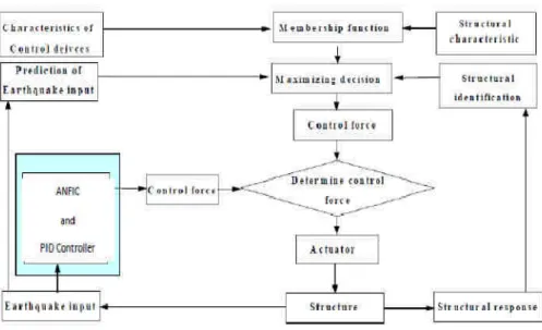
A flow of hybrid active control system
In this paper, intelligent fuzzy control system and reflective fuzzy control system are combined. Intelligent fuzzy control
consists of three systems which are already proposed: (1) prediction of earthquake input (2) structural identifucation (3)fuzzy maximizing decision [Bellman,R.E. and Zadeh,L.A., 1970]. On the other hand, conditioned fuzzy set rules are employed in fuzzy control system.
Figure 5 shows a flow chart of hybrid control system used in this research. This hybrid active control system has the following special and intelligent features,: 1) Objective and constraint conditions of active control are described with membership functions of fuzzy theory, 2) Prediction of earthquake input and the structural identification are performed in real time, 3) An optimal control variable is determined by means of fuzzy maximizing decision, and 4) Fuzzy control system is employed as the reflective fuzzy control system against unexpected large disturbance.
Fig.5: A flow chart of hybrid active control system
V. SIMULATION Numerical Studies
A numerical model of the 5-story example building structure with two MR dampers is implemented in SIMULINK and MATLAB. Using this numerical model, time history analyses of 12 seconds with a time step of 0.004 sec are performed in order to investigate the control performance of MR dampers controlled by the NAGA-II optimized ANFIS Controller and PID Controller. The NSGA-II based optimization is performed with the population size of 100 individuals. An upper limit on the number of generations is specified to be 1000. As the
number of generations increases, the control performance of the elite (i.e. non-dominated) individuals is improved. After optimization run, optimal front (a set of Pareto-optimal solutions) is obtained. Optimization results show that two objective function values of every solution in Pareto-optimal front are less than 1. It means that the NSGA-II optimized ANFIS Controller and PID Controller can provide better control performance in reducing both displacement and acceleration responses compared to the clipped-optimal controller.
Consequently, one controller, that can appropriately control both displacement and acceleration responses, has been
International Journal of Advanced Engineering Research and Science (IJAERS) [Vol-3, Issue-11, Nov- 2016] https://dx.doi.org/10.22161/ijaers/3.11.24 ISSN: 2349-6495(P) | 2456-1908(O)
selected among the Pareto optimal ANFIS Controller and PID Controller. The values of two objectives of the selected ANFIS are both 0.8 and it means that the selected ANFIS Controller and PID Controller can reduce both the peak 5th floor displacement and acceleration responses by 20%,
compared to the clipped optimal controller. The peak responses of the ANFIS Controller and PID Controller, clipped-optimal controller, and uncontrolled case for the five floors of the seismic-excited example building structure are compared in Table 1.
Table.1: Comparison of peak story responses. Story
Displacement (cm) Drift (cm) Acceleration (cm/sec2) Story Uncont rolled PID ANFIS +PID Uncont rolled PID ANFIS +PID Uncont rolled PID ANFIS +PID 1. 0.324 0.096 0.113 0.324 0.096 0.113 497.8 469.8 283.6 2. 0.563 0.187 0.169 0.217 0.096 0.054 670.8 370.7 336.9 3. 0.723 0.255 0.233 0.203 0.093 0.085 486.8 387.9 245.7 4. 0.857 0.327 0.265 0.197 0.076 0.072 542.3 313.2 268.2 5. 0.950 0.045 0.242 0.123 0.054 0.043 840.3 368.3 296.3 ANFIS Controller and PID Controller are 20% smaller than
those of the clipped optimal controller. The peak displacement of the 5th floor of the uncontrolled case is 0.930 cm. On the other hand, the peak displacement of the 5th floor of the ANFIS Controller and PID Controller is 0.218 cm, which is only 30 % of the uncontrolled case. The peak acceleration of the 5th floor of the ANFIS Controller and PID Controller is reduced by 65 % compared to the uncontrolled case. The story drifts of the ANFIS Controller and PID Controller are also about 20% smaller than those of the clipped-optimal controller.
Earthquake Excitation and the response of the structure
In this study, Matlab Simulink with ANFIS and PID Toolbox is used. The aim of the ANFIS control system for the structural system uses the errors in the second storey motion and the derivatives of it as the input variable while the control voltage (u) are their outputs. Reference values are considered to be zero in Figure 6.
Table.2: Rule base for the ANFIS Controller and PID Controller.
Fig.6: Closed loop model of the structure with ANFIS Controller and PID Controller.
A model of the two similar rule bases developed by heuristics with error in body bounce motion, pitch motion and velocity as input variables is given in Table 2, where P, N, Z, B, M, S represent Positive, Negative, Zero, Big, Medium and Small, respectively. A trial and error approach with triangular membership functions has been used to achieve a good controller performance. The membership functions for both scaled inputs (e, de) and output (u) of the controller have been defined on the common interval [–1, 1]. Scaling factors (Se, Sd, Su) are used to set e, de and u (Figure 6) (Mudi and Pal, 1999). The first rule in Table 2 is given below:
If e is XNB and de/dt is V N THEN u is
UNB.
All the rules are written using the Mamdani method to apply to fuzzification. In this study, the centroid method is used in defuzzification. A structural system has been simulated against the earthquake ground motion of the
International Journal of Advanced Engineering Research and Science (IJAERS) https://dx.doi.org/10.22161/ijaers/3.11.2
www.ijaers.com
destructive Gadha earthquake (Mw =6.9
ground motion is used as an input to a building structure. Accelerations were recorded at the Gadha
Table.3: Peak response and peak response reduction
Floor 1 2 3 4 5
It is seen from the Table3 that ANFIS Controller and PID Controller reduces the uncontrolled peak displacement response of the top floor about 49% and 57.5
fifth storey respectively for the Gadha feature of ANFIS Controller and PID Controller in the time history responses of the top floo uncontrolled response when subjected to Gadha
Dynamic Model of the Structural System
In this paper, the simple structure model is used to study the control effect of ANFIS+PID in comparison with
structure, which has three degrees of freedom all in a horizontal direction, is shown in Fig.7
conventional (MR Damper), PID
ANFIS+PID controllers, respectively denoted by controllers and ANFIS+PID controllers, are designed to suppress vibrations of a three - story building against earthquake. The structural system is simulated against the ground accelerations of the Gadha-Jabalpur
India on May 21th, 1997; the Northridge
USA on January 17th, 1994 and the Kobe earthquake in Japan on January 16th, 1995. The control effects of controllers and ANFIS+PID controllers are compared via the time history of the story displacements of the structure.
International Journal of Advanced Engineering Research and Science (IJAERS) https://dx.doi.org/10.22161/ijaers/3.11.24 ISSN: 2349
=6.9). Earthquake ground motion is used as an input to a building structure. Gadha (Jabalpur)
Observatory and Earthquake Research Institute strong motion station at the IIT Rurki,
: Peak response and peak response reduction using different control systems
Peak response of displacement Percentage reduction (%) Uncotrolled ANFIS+PID Control
0.013 0.006 0.026 0.012 0.040 0.018 0.052 0.023 0.065 0.025 ANFIS Controller and PID
reduces the uncontrolled peak displacement 57.5 % for first and earthquake. This ANFIS Controller and PID Controller is revealed of the top floor compared to ted to Gadha earthquake.
ystem
is used to study the in comparison with PID. The structure, which has three degrees of freedom all in a al direction, is shown in Fig.7. In this paper, controllers and respectively denoted by PID , are designed to story building against earthquake. The structural system is simulated against the Jabalpur earthquake in ; the Northridge earthquake in USA on January 17th, 1994 and the Kobe earthquake in 16th, 1995. The control effects of PID are compared via the story displacements of the structure.
Fig.7: The structural system
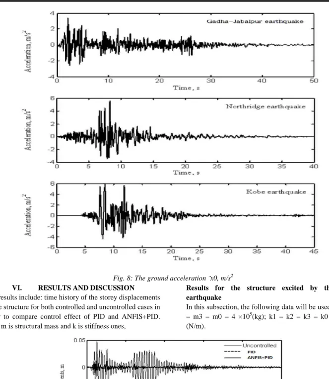
The equations of motion of the system subjected to the ground acceleration ¨x0 (see
Fig. 8), with control force vector {F}, can be written as: [M]{x¨} + [C]{x˙} + [K]{x} = {F}
(1)
where, {x} = [x1 x2 x3]T , {F} = [
is the control force,
the matrices [M], [C] and [K], respectively representing the structural mass, damping and
stiffness ones, are given as follow:
[C] = 0.1 × [M] + 0.003 × [K].
[Vol-3, Issue-11, Nov- 2016] ISSN: 2349-6495(P) | 2456-1908(O)
Page | 144
Observatory and Earthquake Research Institute strong IIT Rurki, India.
in Gadha Earthquake Percentage response reduction (%) 48.0 50.0 52.0 54.3 57.5
The structural system
The equations of motion of the system subjected to the ground acceleration ¨x0 (see
), with control force vector {F}, can be written as:
[M]{x¨} + [C]{x˙} + [K]{x} = {F} − [M]{r}x¨0 , {F} = [−f 0 0]T , {r} = [1 1 1]T . f
the matrices [M], [C] and [K], respectively representing the ss, damping and
stiffness ones, are given as follow:
International Journal of Advanced Engineering Research and Science (IJAERS) [Vol-3, Issue-11, Nov- 2016] https://dx.doi.org/10.22161/ijaers/3.11.24 ISSN: 2349-6495(P) | 2456-1908(O)
Fig. 8: The ground acceleration ¨x0, m/s2
VI. RESULTS AND DISCUSSION
The results include: time history of the storey displacements of the structure for both controlled and uncontrolled cases in order to compare control effect of PID and ANFIS+PID. Here m is structural mass and k is stiffness ones,
Results for the structure excited by the Gadha earthquake
In this subsection, the following data will be used: m1 = m2 = m3 = m0 = 4 ×10⁵(kg); k1 = k2 = k3 = k0 = 2 × 10⁸ (N/m).
International Journal of Advanced Engineering Research and Science (IJAERS) [Vol-3, Issue-11, Nov- 2016] https://dx.doi.org/10.22161/ijaers/3.11.24 ISSN: 2349-6495(P) | 2456-1908(O)
www.ijaers.com Page | 146
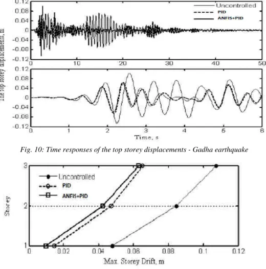
Figs 9 and 10 show the time responses of the first and top storey displacements, respectively. The maximum storey drifts are shown in Fig. 11. Comparison of the effectiveness of the two controllers is presented in Table 4.
Table.4: Comparison of the effectiveness of the three controllers - Gadha earthquake
Building Storey Maximum uncontrolled displacement, m Controlled to uncontrolled displacement ratio PID ANFIS+PID 1 0.047 0.3 0.2 2 0.084 0.55 0.5 3 0.107 0.60 0.53
Results for the structure excited by the Northridge earthquake
In this subsection, the structural data will be changed as follow: m1 = m2 = m3 = m0+ 10%m0; k1 = k2 = k3 = k0 - 10%k0.Figs 12 and 13 show the time response of the top storey displacement and the maximum storey drifts, respectively. Comparison of the effectiveness of the three controllers is presented in Table 5.
Fig. 10: Time responses of the top storey displacements - Gadha earthquake
Fig. 11: The maximum storey drifts - Gadha earthquake
Table.5: Comparison of the effectiveness of the three controllers - Northridge earthquake
Building Storey Maximum uncontrolled displacement, m
Controlled to uncontrolled displacement ratio PID ANFIS+PID
International Journal of Advanced Engineering Research and Science (IJAERS) [Vol-3, Issue-11, Nov- 2016] https://dx.doi.org/10.22161/ijaers/3.11.24 ISSN: 2349-6495(P) | 2456-1908(O)
1 0.070 0.223 0.156 2 0.135 0.456 0.45 3 0.157 0.567 0.534
Results for the structure excited by the Kobe earthquake
In this subsection, another structural parameter will be used as follow: m1 = m2 = m3 = m0 − 10%m0, k1 = k2 = k3 = k0 + 10%k0.
Fig.12: Time responses of the top storey displacements - Northridge earthquake
Fig. 13: The maximum storey drifts - Northridge earthquake
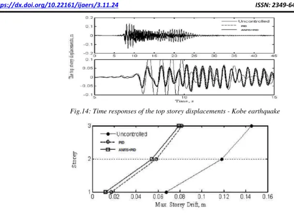
Figs 14 and 15 show the time response of the top storey displacement and the maximum storey drifts, respectively. Comparison of the effectiveness of the three controllers is presented in Table 6.
Table.6: Comparison of the effectiveness of the three controllers - Kobe earthquake
Building Storey Maximum uncontrolled displacement, m Controlled to uncontrolled displacement ratio PID ANFIS+PID 1 0.065 0.256 0.176 2 0.114 0.456 0.461 3 0.135 0.563 0.545
International Journal of Advanced Engineering Research and Science (IJAERS) [Vol-3, Issue-11, Nov- 2016] https://dx.doi.org/10.22161/ijaers/3.11.24 ISSN: 2349-6495(P) | 2456-1908(O)
www.ijaers.com Page | 148
Fig.14: Time responses of the top storey displacements - Kobe earthquake
Fig. 15: The maximum storey drifts - Kobe earthquake
As shown in above - mentioned figures and tables, vibration amplitudes of the storeys are decreased successfully with PID and ANFIS+PID for the structure with the different structural data excited by three different earthquakes. It allows partially evaluating the stability and robustness capacities the proposed controller - ANFIS+PID. With the case of the Gadha earthquake, the reduction ratios (ratio of the con- trolled to uncontrolled response) for maximum displacement of the top floor of the structure are about 61% and 59% for the PID and ANFIS+PID, respectively (Fig. 11 and Table 5). Therefore, it is seen that the ANFIS+PID is more effective than the PID in view of reducing the displacement response of the structure. The effectiveness of two controllers in reducing the response of the structure due to other two earthquakes (Northridge and Kobe) is also shown for comparison in Figs. 13 and 15 and Tables 6 - 7. Almost the same behavior as for the Gadha earthquake can be observed for these earthquakes too.
A Simulink model of the system, which consisted of the selected building, was created and simulations were performed using MATLAB. It is seen from the Table 3 that ANFIS Controller and PID Controller reduces the uncontrolled peak displacement response of the top floor about 49% and 57.5 % for first and fifth storey respectively for the Gadha earthquake. This feature of ANFIS Controller and PID Controller is revealed in the time history responses
of the top floor compared to uncontrolled response when subjected to Gadha earthquake.
VII. CONCLUSIONS
The safety of the structures mainly depends on the displacement response, while the comfort level of the occupants depends on the acceleration response. To ensure that both responses are within permissible limits, ANFIS controller and PID controller have been designed for a multi-degree-of-freedom system having the parameters of a real structure under the non-linear behavior of soil-structure interaction, and simulation results have been presented. The main idea behind proposing ANFIS controller is its success and the ability of using these types of controllers on structural systems. Because the destructive effect of earthquakes is a result of horizontal vibrations, in this study the degrees of freedom were assumed only in this direction. The system is modeled including the dynamics of a linear motor which is used as the active isolator, and the structural system is then subjected to Gadha earthquake vibration effects, which are treated as disturbance. The simulation results indicate that the implementation of ANFIS+PID controllers shows a good response as far as absorbing the vibration due to earthquake effects. Essential performance requirements for the safety of the structures and comfort level for the user are achieved. The displacements of the fifteenth storey are minimized successfully using the
International Journal of Advanced Engineering Research and Science (IJAERS) [Vol-3, Issue-11, Nov- 2016] https://dx.doi.org/10.22161/ijaers/3.11.24 ISSN: 2349-6495(P) | 2456-1908(O)
ANFIS+PID controller. The designed ANFIS+PID show high performance. A designed ANFIS+PID controller brought better active control performance than a PID controller. The improvement in resonance values and the decrease in vibration amplitudes support this result and the proposed fuzzy logic controller has great potential in active structural control.
This study investigates the control performance of the ANFIS Controller and PID Controller optimized by an NAGA-II for control of a 5-story building subjected to earthquake. For comparison purpose, a clipped-optimal control algorithm is considered as the baseline. Based on numerical simulations, it can be seen that the NAGA-II optimized ANFIS Controller and PID Controller can effectively reduce both displacement and acceleration responses of the building structure by 20% compared to the clipped optimal control algorithm. After single optimization run using NSGA-II, an engineer can simply select another ANFIS Controller that satisfies the desired performance requirements from among a number of Pareto optimal solutions. It would be important characteristics of the NSGA-II based optimization compared to other optimization methods.
REFERENCES
[1] Al-Dawod, M., Samali, B., Kwok, K., and Naghdy, F., 2004, “Fuzzy controller for seismically excited nonlinear buildings,” Journal of Engineering Mechanics 130(4), 407–415.
[2] Guclu, R., 2006, “Sliding mode and PID control of a structural system against earthquake,” Mathematical
and Computer Modelling 44(1–2), 210–217.
[3] Li, N.H., Jia, Y., andWang, S.Y., 2004, “Theoretical and experimental studies on reduction for multi-modal seismic responses of high-rise structures by tuned liquid dampers,” Journal of Vibration and Control
10(7), 1041–1056.
[4] Battaini M, Casciati F, Faravelli L. Fuzzy control of structural vibration. An active mass system driven by a fuzzy controller, Earthquake Engineering and Structural Dynamics, No.11,27(2004)1267-76.
[5] Al-Dawod M, Samali B, Li J. Experimental verification of an active mass driver system on a five-storey model using a fuzzy controller, Structural
Control and Health Monitoring, No.5, 13(2006)
917-43.
[6] Pourzeynali S, Lavasani HH, Modarayi AH. Active control of high rise building structures using fuzzy logic and genetic algorithms, Engineering Structures, No. 3, 29(2007) 346-57.
[7] Guclu R, Yazici H. Vibration control of a structure with ATMD against earthquake using fuzzy logic controllers, Journal of Sound and Vibration, No. 1–2,
318(2008) 36-49.
[8] Li L, Song G, Ou J. Hybrid active mass damper (AMD) vibration suppression of nonlinear high-rise structure using fuzzy logic control algorithm under earthquake excitations, Structural Control and Health
Monitoring, No. 6, 18(2011) 698-709.
[9] Venanzi I, Ubertini F, Materazzi AL. Optimal design of an array of active tuned mass dampers for wind-exposed high-rise buildings, Structural Control and
Health Monitoring, No. 6, 20(2013) 903-17.
[10]Mendel JM, John RI, Liu F. Interval type-2 fuzzy logic systems made simple, Fuzzy Systems, IEEE Transactions on, No. 6, 14(2006) 808-21.
[11]Mendel JM. Advances in type-2 fuzzy sets and systems, Info. Sciences, No. 1, 177(2007) 84-110. [12]L.-Y.Lu, G.-L.Lin, T.-C.Kuo, Stiffness controllable
isolation system for near-fault seismic isolation. Engineering Structures, vol. 30, p. 747-765, 2008 [13]S.M.Yang, C.J.Chen, W.L.Huang, Structural Vibration
Suppression by a Neural-Network Controller with a Mass-Damper Actuator. Journal of Vibration and Control, vol. 12(5), p. 495-508, 2006
[14]W.S.Oates, R.C.Smith, Nonlinear Optimal Control
Techniques for Vibration Attenuation Using Magnetostrictive Actuators. Jr. of Intelligent Material Systems and Structures, vol. 19, p.193-209, 2008 [15]S.Pourzeynali, H.H.Lavasani, A.H.Modarayi, Active
control of high rise building structures using fuzzy logic and genetic algorithms. Engineering Structures,
vol. 29, p. 346-357, 2007
[16]I.Dumitrache, Ingineria Reglarii Automate (Control
Systems Engineering). Editura Politehnica Press, Bucharest, Romania, 2010
[17]M.Bitaraf, O.E.Ozbulut, S.Hurlebaus, L.Barrosso,
Application of semi-active control strategies for seismic protection of buildings. Engineering Structures, vol. 32, p. 3040-3047, 2010
[18]Dyke, S.J., Spencer, B.F., Jr., Sain, M.K., Carlson, J.D.: Modeling and Control of Magnetorheological Dampers for Seismic Response Reduction. Smart Mat and Struct, Vol. 5, pp. 565-575 (1996).
[19]R.O. Duda, P.E. Hart, D.G. Stock, Pattern
classification, 2nd edition, John Wiley and Sons, New
York, 2001.
[20]Qureshi Mohd. Farukh, Jha Manoj, Sao Gopi,(2009)“Fuzzy interval theory based governing control and excitation control for stability of power
International Journal of Advanced Engineering Research and Science (IJAERS) [Vol-3, Issue-11, Nov- 2016] https://dx.doi.org/10.22161/ijaers/3.11.24 ISSN: 2349-6495(P) | 2456-1908(O)
www.ijaers.com Page | 150
system.” Advances in Modelling C Automatic Control (theory and applications), Vol. 64, Issue 1,pp1-19. [21]Qureshi M. F.,Bharti I.C. (2006) “Fuzzy based study
and simulation of local heat transfer coefficient at Circumference of horizontal tube in free board region of fluidized bed” AMSE Journals, Modeling-B, Vol.75,Issue 2, pp1-20.
[22]Qureshi M.F.,Devangan P. and Devangan N.P. (2010) “Mamdani-ANFIS and its application of student’s value” AMSE Journals,Modeling-D, Vol 31,issue 1,pp 65-74.
[23]Qureshi et.al. (2006) “Design of fuzzy rule-based classifier for data mining from library data warehouse using EMO algorithms”.AMSE Journals, Advances-D, Vol.11, Issue 4, pp 31-42.