IT'16
INFORMACIONE
TEHNOLOGIJE
-
SADAŠNJOST I BUDUĆNOST
-
Urednik
Božo Krstajić
Zbornik radova sa XXI međunarodnog naučno - stručnog skupa
INFORMACIONE TEHNOLOGIJE - sadašnjost i budućnost
Zbornik radova
INFORMACIONE TEHNOLOGIJE - sadašnjost i budućnost 2016
Glavni urednik
Prof. dr Božo Krstajić
Izdavač
Univerzitet Crne Gore
Elektrotehnički fakultet
Džordža Vašingtona bb., Podgorica
www.etf.ucg.ac.me
Tehnička obrada
Aleksandra Radulović
Centar informacionog sistema
Univerziteta Crne Gore
Tiraž
150
Podgorica 2016.
Organizator
Elektrotehnički fakultet, Univerzitet Crne Gore
Suorganizatori:
BIO-ICT Centar izvrsnosti
Skup su podržali:
Ministarstvo za informaciono društvo i telekomunikacije
Ministarstvo nauke
Programski odbor
Dr Novak Jauković, Elektrotehnički fakultet, Podgorica, MNE
Dr Ljubiša Stanković, Elektrotehnički fakultet, Podgorica, MNE
Dr Zdravko Uskoković, Elektrotehnički fakultet, Podgorica, MNE
Dr Vujica Lazović, Ekonomski fakultet, Podgorica, MNE
Dr Branko Kovačević, Elektrotehnički fakultet, Beograd, SRB
Dr Milorad Božić, Elektrotehnički fakultet, Banja Luka, BIH
Dr Miroslav Bojović, Elektrotehnički fakultet, Beograd, SRB
Dr Zoran Jovanović, Elektrotehnički fakultet, Beograd, SRB
Dr Milica Pejanović-Đurišić, Elektrotehnički fakultet, Podgorica, MNE
Dr Despina Anastasiadou, Research & Development Innovation Academy, Solun, GRC
Dr Dejan Popović, Elektrotehnički fakultet, Beograd, SRB
Dr Gabriel Neagu, National Institute for Research & Development in Informatics,
Bucharest, ROU
Dr Božo Krstajić, Elektrotehnički fakultet, Podgorica, MNE
Dr Tomo Popović, Elektrotehnički fakultet, Podgorica, MNE
Dr Milovan Radulović, Elektrotehnički fakultet, Podgorica, MNE
Dr Le Xie, Texas A&M University, College Station, TX, USA
Dr Sašo Gelev, Elektrotehnički fakultet, Radoviš, MKD
Dr Budimir Lutovac, Elektrotehnički fakultet, Podgorica, MNE
Dr Igor Radusinović, Elektrotehnički fakultet, Podgorica, MNE
Dr Alex Sprintson, Texas A&M University, College Station, TX, USA
Dr Nikša Tadić, Elektrotehnički fakultet, Podgorica, MNE
Dr Miloš Daković, Elektrotehnički fakultet, Podgorica, MNE
Dr Milutin Radonjić, Elektrotehnički fakultet, Podgorica, MNE
Dr Ana Jovanović, Elektrotehnički fakultet, Podgorica, MNE
Dr Vesna Rubežić, Elektrotehnički fakultet, Podgorica, MNE
Dr Ramo Šendelj, Fakultet za Informacione Tehnologije, Podgorica, MNE
Dr Stevan Šćepanović, Prirodno-matematički fakultet, Podgorica, MNE
Organizacioni odbor
Dr Božo Krstajić,Elektrotehnički fakultet, Podgorica, MNE
Dr Milovan Radulović, Elektrotehnički fakultet, Podgorica, MNE
Dr Zoran Veljović, Elektrotehnički fakultet, Podgorica, MNE
Dr Ana Jovanović, Elektrotehnički fakultet, Podgorica, MNE
Dr Saša Mujović, Elektrotehnički fakultet, Podgorica, MNE
Dr Tomo Popović, Elektrotehnički fakultet, Podgorica, MNE
Dr Žarko Zečević, Elektrotehnički fakultet, Podgorica, MNE
Vladan Tabaš, dipl.ing., Čikom, Podgorica, MNE
Sekretarijat
II
Gordana Laštovička-Medin
EMERGING INTERFACES FOR CONCEPTUAL CHANGE: CO-DESIGNING MODEL OF
COPERATION OF LEARNER, ARTIFACT – LEGO NXT AND REMOTE LAB
EMERGING INTERFEJSI ZA KONCEPTUALNE PROMJENE: KODIZAJNIRANI MODEL
KOOPERACIJE UČENIKA, ARTIFACTA – LEGO NXT I UDALJENE LABORATORIJE ... 34
Vasilija Šarac, Sašo Gelev, Goce Stefanov, Vlatko Čingoski
PRIMENA PROGRAMSKOG PAKETA PSIM U SIMULACIJI ENERGETSKIH PRETVARAČA
APPLICATION OF SOFTWARE PSIM IN SIMULATION OF POWER CONVERTERS ... 38
Sanja Bauk
IoT PRIMJENE I NJIHOV UTICAJU NA DIGITALNU PODJELU
IoT’s APPLICATIONS AND THEIR IMPACT ON DIGITAL DIVIDE ... 42
Aleksandar Ristić, Sandra Ristić
ŠKOLSKI I POSLIJEŠKOLSKI PROGRAMI – INFORMACIONO DRUŠTVO REPUBLIKE SRPSKE
SCHOOL AND AFTERSCHOOL PROGRAMS – IT SOCIETY OF REPUBLIC OF SRPSKA ... 46
Maja Kukusheva Paneva, Biljana Chitkusheva Dimitrovska, Goce Stefanov, Vasilija Šarac
PRIMENA PROGRAMSKOG PAKETA PSIM U PROUČAVANJA DIODNOG ISPRAVLJAČA
PSIM AS EDUCATIONAL TOOL FOR TEACHING DIODE RECTIFIER ... 50
Marko Bošković
UMREŽENI UPRAVLJAČKI SISTEMI
NETWORKED CONTROL SYSTEMS... 53
Tomislav B. Šekara, Marko Bošković, Milovan Radulović, Boško Cvetković
NOVA METODA ZA OPTIMIZACIJU PIDC REGULATORA POD OGRANIČENJIMA NA
PRETEK FAZE I OSJETLJIVOST NA MJERNI ŠUM
A NOVEL METHOD FOR OPTIMIZATION OF PIDC REGULATORS UNDER CONSTRAINTS
ON PHASE MARGIN AND SENSITIVITY TO MEASUREMENT NOISE ... 57
Marko Bursać, Goran Tričković, Radislav Vulović
PROJEKTOVANJE INFORMACIONOG SISTEMA ZA AUTOMATIZACIJU POSLOVNIH
PROCESA RADIO LOKOMOTIVSKIH UREĐAJA
DESIGN INFORMATION SYSTEM FOR AUTOMATION BUSINESS PROCESSES OF RADIO
LOCOMOTIVE DEVICES ... 61
Bojan Ćuković, Saša Mujović
NEOVLAŠĆENO KORIŠĆENJE ELEKTRIČNE ENERGIJE U USLOVIMA PRIMJENE
BROJILA NA DALJINSKO OČITAVANJE
UNAUTHORIZED USE OF ELECTRICITY IN TERMS OF APPLICATION OF SMART METERS .... 65
Boško Cvetković, Mihailo Lazarević, Taško Maneski, Petar Mandić, Budimir Lutovac, Tomislav B. Šekara
AKVIZICIJA PODATAKA KORIŠĆENJEM RAZVOJNE PLOČE RASPBERRI PI MODEL B
DATA ACQUISITION USING SINGLE BOARD COMPUTER RASPBERRY PI MODEL B ... 69
Duško Parezanović, Dragan Vidaković
PRAKSA RSA ŠIFROVANJA
Informacione tehnologije IT'16
PRIMENA PROGRAMSKOG PAKETA PSIM U SIMULACIJI ENERGETSKIH PRETVARAČA
APPLICATION OF SOFTWARE PSIM IN SIMULATION OF POWER CONVERTERS
Vasilija Šarac, Sašo Gelev, Goce Stefanov and Vlatko Čingoski, Faculty of Electrical Engineering, University Goce Delecev, Stip, R.Macedonia
Sadržaj: Rad prikazuje primenu softverskog paketa PSIM koji omogučava simulaciju rada energetskih pretvarača i na taj način zamenjuje skupu labaratorisku opremu. Razrađeni su dva primera energetskh pretvarača i to trofazni kontrolisani ispravljač i trofazni invertor kao elektronski sklopovi koji imaju široku primenu u praksi. Upoređeni su teoretski dobijeni rezultati ulaznih i izlanih napona iz svakog tipa pretvarača i naponi dobijeni pomoću simulacije. Na osnovi toga izvedeni su zaključci o uspešnosti primene softverskog paketa PSIM u simulacii rada energetskih pretvarača kao pomoćnog sredstva u laboratorijskim vežbama.
Abstract: Paper presents application of software PSIM in simulation of operation of power converters as an replacement of expensive laboratory equipment. Two different examples are worked out in the paper. First one is a three phase controlled bridge rectifier and the second one is three phase inverter , both chosen as a result of their wide practical application. A comparison between theoretical results of input and output voltages from the converters and from the simulation is presented. Based on the comparison conclusions are made about the success of the application of PSIM in simulation of power converters as an auxiliary tool in laboratory exercises.
1. INTRODUCTION
Power converters have wide application in electrical industry but as well as in every-day life. They are used in battery chargers of many electronic devices, in lightening, in uninterruptible power supplies (UPS) but as well as in more sophisticated applications such as controlled electrical drives with adjustable speed of operation [1]-[3]. They provide the desired electrical parameters of the power supply (form of the voltage: DC or AC, the amplitude and the frequency). Understanding their principles of operation is very important for their proper usage. Simulation software is often used as an adequate replacement of an expensive laboratory equipment enabling the choice of adequate electronic components, their connections in the scheme of the power converter, adequate setting and triggering of electronic components and finally obtaining the waveforms of input and output voltage[4]-[5]. This philosophy is applied in analysis and simulation of power converter circuits analyzed as part of undergraduate course of power converters within Faculty of Electrical Engineering at University “Goce Delcev”. Original simulation models of different types of converters are developed in simulation software PSIM. The software itself offers broad possibilities for analysis of different types of electronic circuits due to its extensive library of electronic components and their controlling circuits. The user friendly interface enables quick and easy creation of electronic circuits and evaluation of obtained results without any prior knowledge of the software itself or any programming experience compared to other simulation software like Matlab or Simulnik. In this paper two different types of power converters are analyzed. First one is three phase controlled bridge rectifier often used as industrial rectifier in numerous electrical facilities where DC voltage is need as an auxiliary voltage for signaling and command purposes. The second one is a three phase inverter
often used in three phase UPS applications, as a part of electricity production from solar panels or in the adjustable speed drives. Theoretical bases of both power converters are presented together with their principle of operation, basic equations and waveforms of input and output voltages. Creation of electrical scheme is explained together with the controlling scheme of electronic components. On the oscilloscope are recorded input and output waveforms and they are compared with theoretical results.
2. PRINCPLE OF OPERATION
2.1. THREE-PHASE CONTROLLED BRIDGE RECTIFIER
Most of the bridge schemes of power converter use six electronic components (diodes, thyristors or transistor) most often three of them connected in the upper part of the bridge and three in the lower part of the bridge (Fig.1). In order to have rectified output voltage one electronic component from upper part of the bridge is in the conducting state or ON state and one from the lower part of the bridge. For example in our case must be simultaneously in ON position the thyristors T1 and T2, than T3 and T2, than T3 and T4 etc.. As the name indicates the power supply on the input of the rectifier is three phase symmetrical power supply with line voltages 380 V, and supply frequency of 50 Hz.
Fig.1 Electrical connection of three-phase rectifier
Informacione tehnologije IT'16
The line input voltages are presented in Fig. 2 a. Since the bridge is controlled which means that mean and rms value of the output voltage can be controlled the electronic components used in the rectifier are thyristors which are switched on only when the control signal is applied on the gate of the thyristor and when voltage on its anode is higher than the voltage on the cathode. This means that by controlling the moment when the thyristors are switched on , i.e. the angle of the input voltage for which the thyristor are switched on-α, the output voltage, its mean and rms value is controled as well [6].
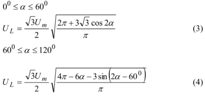
Fig. 2 Input and output voltage waveforms from rectifier Two operational regimes of the rectifier are distinguished. When control angle (α) of the thyristors is within the range 0º-60º rectifier is working in the continuous current mode. When control angle is increased within the range 60º-120º rectifier is operating in the discontinuous current mode. Mean value of the rectified voltage on the load side for
0 0 60 0 is:
cos cos 3 3 30 sin 3 3 01 90 30 0 0 0 dc m m dc U U t d t U U
(1)Where Udc01 is the mean value of rectified voltage on load
side when control angle α=0.
For interval 6001200the mean value of load voltage is:
1 cos 600
3 3 m dc U U (2)Rms value of the output voltage for both operation modes of the converter is:
0 0 60 0 3 3cos2 2 2 3 m L U U (3) 0 0 120 60
6 3sin 2 600 4 2 3 m L U U (4)Operation of the rectifier and output waveforms are presented for active load (resistance).
2.2. THREE-PHASE INVERTER
Three phase inverters enable transformation of DC voltage to AC with adjustable amplitude and frequency of output voltage. As well as the bridge rectifiers three phase invertors operate in bridge connection with six controlled electronic components (thyristors or transistor).
Fig.3 Three-phase inverter
Simultaneously are switch on one transistor from the upper part of the bridge and one from the lower part. The output phase voltages UAN, UBN and UCN as well as the line voltage
UAB are presented in Fig.4 [6].
Fig.4 Output waveforms from the inverter
c) a) b) d) e) 39
Informacione tehnologije IT'16
Output waveforms of the voltage in Fig.4 are presented for operation of the voltage inverter at no-load. But the output waveforms in case of no-load and connected resistive load to A,B,C, connection from Fig. 3 are identical. So following equations are valid:
0<t< 60 dc dc L AN
R
R
V
V
R
I
u
2
2
(5)0
BNu
(6) dc dc L CNR
R
V
V
R
I
u
2
2
(7) dc BN AN NB AN ABu
u
u
u
V
u
(8) 60<t< 120 0 AN u (9) dc L BN I R V u (10) dc L CN I R V u (11) dc AB V u (12) 120<t< 180 dc L AN I R V u (13) dc L BN I R V u (14) 0 CN u (15) dc AB V u 2 (16) 3. SIMULATION MODELS3.1.THREE-PHASE CONTROLLED BRIDGE RECTIFIER
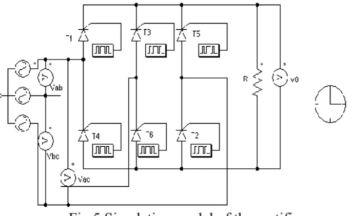
Simulation package PSIM and its student version offer sufficient number of elements for simulation of electronic or electrical circuits. In this case it will be used for creation of electronic circuits of power converters described above. In case of three-phase controlled rectifier all electronic elements (thyristors) are connected according to the Fig.1. Three-phase symmetrical power supply is connected on the input of the rectifier. Operation of thyristors is controlled by their gates. From the other hand, gates are controlled by series of pulses connected to them (Fig. 5). Sequence of operation of thyristors is presented in Table.1 The angle of switching on of thyristors is 30º.
Table 1. Sequence of operation of thyristors at rectifier Тhyristor Switching angles
Т1 60 70. 120 130. Т2 120 130. 180 190. Т3 180 190. 240 250. Т4 240 250. 300 310. Т5 300 310. 360 370. Т6 60 70. 360 370.
Input and output voltages from the rectifier are presented in Fig. 5.
Fig.5 Simulation model of the rectifier
The simulation time is controlled and adjusted via the clock (Fig.5). Adequate voltmeters are connected on input and output side of the rectifier in order input line voltages Uab, Uac
and Ubc to be measured as well as output voltage Uo.
Fig.6 Waveforms of input and output voltage from rectifier 3.2. THREE-PHASE INVERTER
Simulation model of three-phase voltage inverter is based on electrical scheme from Fig.3. Input DC voltage is transformed into AC rectangular voltage waveforms by implementing the adequate sequence of operation of transistors (Table 2). The amplitude of the input voltages is 200 V.
Fig.7 Simulation model of the inverter
As electronic switches are used IGBT transistors controlled by the pulse signal applied on their gates.
Informacione tehnologije IT'16
Table 2. Sequence of operation of transistors at inverter Transistor Sequence of operation IGBT1 0 60. 300 360 IGBT2 0 60. 60 120. IGBT3 60 120. 120 180. IGBT4 120 180. 180 240. IGBT5 180 240. 240 300 IGBT6 240 300. 300 360
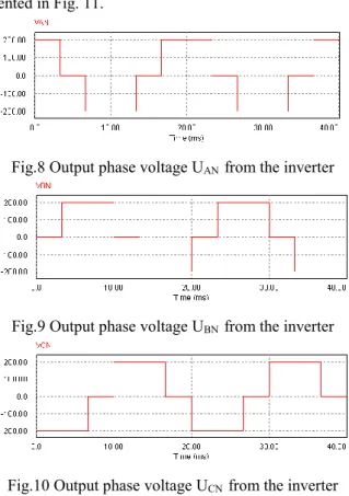
Output phase voltages UAN,UBN and UCN are presented in
Figs. 8,9 and 10 consecutively. The line voltage UAB is
presented in Fig. 11.
Fig.8 Output phase voltage UAN from the inverter
Fig.9 Output phase voltage UBN from the inverter
Fig.10 Output phase voltage UCN from the inverter
Fig. 11 Output line voltage UAB from the inverter
From comparison of presented results from Fig. 2 c) and Fig. 6 it is evident the similarity of output voltage waveforms in case of three-phase controlled bridge rectifier when switching angle of thyristors is 30 º. The presented results of output line voltage from the simulation model of the inverter (Fig. 8, 9 and 10) are adequate to the presented theoretical result (Fig.4). Output voltage from the inverter (Fig.11) is in complete agreement with Fig.4 and (5)(16). Therefore it can
be concluded that software PSIM is modelling the power converters with satisfactory accuracy and it enables overview of the basic principles of their operation
4. CONCLUSION
Power converters are widely used electronic devices in application where transformation of voltage parameters such as waveform, amplitude or frequency is necessary. Online recording of input and output voltage of the converters often requires expensive equipment. Therefore for the purpose of laboratory exercises for the students, software PSIM is introduced as a replacement. Paper has presented the simulation models of two types of converters and has proved that for basic understanding of principle of operation of power converters student version of software PSIM is operating satisfactorily. More complex models of power converters requires more complex control circuits and adequate filters which can be modelled by advanced versions of the software and used in professional design of power converters.
REFERENCES
[1] G.Stefanov, Lj. Karadzinov "Control and data log of functions for protection in the hydraulic excavator”, Comptes rendus de l’Academie bulgare des Sciences , Vol.63, No.6, pp. 909-916, 2011.
[2] G.Stefanov, Lj. Karadzinov "Mathematical calculation of H bridge IGBT power convertor”, Comptes rendus de l’Academie bulgare des Sciences , Vol.64, No.6, pp.
897-904 ,2012.
[3] P. Rodriguez P, J. Pou , J. Bergas, J.I. Candela , R.P. Burgos, D. Boroyevich, “Decoupled Double Synchronous Reference Frame PLL for Power Converters Control”, IEEE Transactions of Power Electronics, Vol.22, No.2, pp. 584-592, 2007.
[4] P. Rodríguez, A. Luna, I. Candela , R. Mujal, R. Teodorescu, F. Blaabjerg, “Multiresonant Frequency-Locked Loop for Grid Synchronization of Power Converters Under Distorted Grid Connections”, IEEE Transactions of Industrial Electronics, Vol. 58, No.1, pp. 127-138, 2010.
[5] J. Rocabert, A.Luna, F. Blaabjerg , P. Rodríguez, “Control of Power Converters in AC Microgrids”, IEEE Transactions on Power Electronics, Vol. 27, No.11, pp. 4734-4749, 2012.
[6] W. Shepherd, L. Zhang “ Power Converter Circuits”, Marcel Dekker Inc, 2004